www.s-a-m.com User Manual Workbench Create and Customize User Interfaces for Router Control

Welcome message from author
This document is posted to help you gain knowledge. Please leave a comment to let me know what you think about it! Share it to your friends and learn new things together.
Transcript
User Manual
WorkbenchCreate and Customize User Interfaces for Router Control
www.s-a-m.com

WorkBench User Manual
Issue1 Revision 5 Page 2 © 2017 SAM
WorkBench User Manual Information and Notices
Information and Notices
Copyright and Disclaimer
Copyright protection claimed includes all forms and matters of copyrightable material and information now allowed by statutory or judicial law or hereinafter granted, including without limitation, material generated from the software programs which are displayed on the screen such as icons, screen display looks etc.
Information in this manual and software are subject to change without notice and does not represent a commitment on the part of SAM Limited. The software described in this manual is furnished under a license agreement and can not be reproduced or copied in any manner without prior agreement with SAM Limited, or their authorized agents.
Reproduction or disassembly of embedded computer programs or algorithms prohibited.
No part of this publication can be transmitted or reproduced in any form or by any means, electronic or mechanical, including photocopy, recording or any information storage and retrieval system, without permission being granted, in writing, by the publishers or their authorized agents.
SAM operates a policy of continuous improvement and development. SAM reserves the right to make changes and improvements to any of the products described in this document without prior notice.
Contact Details
Customer Support
For details of our Regional Customer Support Offices and contact details please visit the SAM web site and navigate to Support/247-Support.
www.s-a-m.com/support/247-support/
Customers with a support contract should call their personalized number, which can be found in their contract, and be ready to provide their contract number and details.
Trademarks
Microsoft, Microsoft Windows and Windows are either registered trademarks or trademarks of Microsoft Corporation in the United States and/or other countries.
All other trademarks or registered trademarks are the property of their respective owners.
Issue1 Revision 5 Page 3 © 2017 SAM

WorkBench User Manual Information and Notices
Issue1 Revision 5 Page 4 © 2017 SAM
WorkBench User Manual
Contents
1 Introduction . . . . . . . . . . . . . . . . . . . . . . . . . . . . . . . . . . . . . . . . . . . . . . . . . . . . . . . . 111.1 Description . . . . . . . . . . . . . . . . . . . . . . . . . . . . . . . . . . . . . . . . . . . . . . . . . . . . . .111.2 Database Configuration. . . . . . . . . . . . . . . . . . . . . . . . . . . . . . . . . . . . . . . . . . . . .111.3 Architecture . . . . . . . . . . . . . . . . . . . . . . . . . . . . . . . . . . . . . . . . . . . . . . . . . . . . . 121.4 Configurations for Multiple Routers . . . . . . . . . . . . . . . . . . . . . . . . . . . . . . . . . . . 131.5 Protocols . . . . . . . . . . . . . . . . . . . . . . . . . . . . . . . . . . . . . . . . . . . . . . . . . . . . . . . 15
2 Installation . . . . . . . . . . . . . . . . . . . . . . . . . . . . . . . . . . . . . . . . . . . . . . . . . . . . . . . . . 172.1 System Requirements . . . . . . . . . . . . . . . . . . . . . . . . . . . . . . . . . . . . . . . . . . . . . 17
2.1.1 Minimum Installation Requirements . . . . . . . . . . . . . . . . . . . . . . . . . . . . . . 172.2 Install Workbench . . . . . . . . . . . . . . . . . . . . . . . . . . . . . . . . . . . . . . . . . . . . . . . . 172.3 Finish the Installation. . . . . . . . . . . . . . . . . . . . . . . . . . . . . . . . . . . . . . . . . . . . . . 232.4 Manually Installing Components . . . . . . . . . . . . . . . . . . . . . . . . . . . . . . . . . . . . . 23
2.4.1 Configuration Helper Display. . . . . . . . . . . . . . . . . . . . . . . . . . . . . . . . . . . . 232.4.2 Support . . . . . . . . . . . . . . . . . . . . . . . . . . . . . . . . . . . . . . . . . . . . . . . . . . . . 252.4.3 Computer . . . . . . . . . . . . . . . . . . . . . . . . . . . . . . . . . . . . . . . . . . . . . . . . . . 252.4.4 Microsoft Data Access Components . . . . . . . . . . . . . . . . . . . . . . . . . . . . . . 262.4.5 Visual C++ Redistributable . . . . . . . . . . . . . . . . . . . . . . . . . . . . . . . . . . . . . 262.4.6 SQL Server . . . . . . . . . . . . . . . . . . . . . . . . . . . . . . . . . . . . . . . . . . . . . . . . . 272.4.7 SQL Server Management Studio . . . . . . . . . . . . . . . . . . . . . . . . . . . . . . . . 272.4.8 Workbench Database . . . . . . . . . . . . . . . . . . . . . . . . . . . . . . . . . . . . . . . . . 282.4.9 Add a Mirrored Server . . . . . . . . . . . . . . . . . . . . . . . . . . . . . . . . . . . . . . . . . 292.4.10 Create a New Database Using SQLDBTool . . . . . . . . . . . . . . . . . . . . . . . 302.4.11 Create a Blank Database Using SQLMS. . . . . . . . . . . . . . . . . . . . . . . . . . 312.4.12 Install Sample Databases . . . . . . . . . . . . . . . . . . . . . . . . . . . . . . . . . . . . . 31
2.5 Start Workbench . . . . . . . . . . . . . . . . . . . . . . . . . . . . . . . . . . . . . . . . . . . . . . . . . 312.6 Log In to Workbench . . . . . . . . . . . . . . . . . . . . . . . . . . . . . . . . . . . . . . . . . . . . . . 332.7 LiveRunner . . . . . . . . . . . . . . . . . . . . . . . . . . . . . . . . . . . . . . . . . . . . . . . . . . . . . 34
2.7.1 Command Line Parameters . . . . . . . . . . . . . . . . . . . . . . . . . . . . . . . . . . . . 342.8 Pbak DeployTool . . . . . . . . . . . . . . . . . . . . . . . . . . . . . . . . . . . . . . . . . . . . . . . . . 35
2.8.1 Description . . . . . . . . . . . . . . . . . . . . . . . . . . . . . . . . . . . . . . . . . . . . . . . . . 352.8.2 Configuration. . . . . . . . . . . . . . . . . . . . . . . . . . . . . . . . . . . . . . . . . . . . . . . . 35
2.9 Configuration Helper Utility . . . . . . . . . . . . . . . . . . . . . . . . . . . . . . . . . . . . . . . . . 35
3 General Operation . . . . . . . . . . . . . . . . . . . . . . . . . . . . . . . . . . . . . . . . . . . . . . . . . . . 373.1 Screen Layout . . . . . . . . . . . . . . . . . . . . . . . . . . . . . . . . . . . . . . . . . . . . . . . . . . . 37
3.1.1 Home Screen . . . . . . . . . . . . . . . . . . . . . . . . . . . . . . . . . . . . . . . . . . . . . . . 373.1.2 Mode Windows . . . . . . . . . . . . . . . . . . . . . . . . . . . . . . . . . . . . . . . . . . . . . . 38
3.2 Run Screen . . . . . . . . . . . . . . . . . . . . . . . . . . . . . . . . . . . . . . . . . . . . . . . . . . . . . 393.3 Change User . . . . . . . . . . . . . . . . . . . . . . . . . . . . . . . . . . . . . . . . . . . . . . . . . . . . 393.4 Log . . . . . . . . . . . . . . . . . . . . . . . . . . . . . . . . . . . . . . . . . . . . . . . . . . . . . . . . . . . 393.5 Exit Workbench . . . . . . . . . . . . . . . . . . . . . . . . . . . . . . . . . . . . . . . . . . . . . . . . . . 40
4 Administration . . . . . . . . . . . . . . . . . . . . . . . . . . . . . . . . . . . . . . . . . . . . . . . . . . . . . . 414.1 Description . . . . . . . . . . . . . . . . . . . . . . . . . . . . . . . . . . . . . . . . . . . . . . . . . . . . . 414.2 Users . . . . . . . . . . . . . . . . . . . . . . . . . . . . . . . . . . . . . . . . . . . . . . . . . . . . . . . . . . 41
4.2.1 Add a New User . . . . . . . . . . . . . . . . . . . . . . . . . . . . . . . . . . . . . . . . . . . . . 424.2.2 Delete a User . . . . . . . . . . . . . . . . . . . . . . . . . . . . . . . . . . . . . . . . . . . . . . . 42
4.3 Roles . . . . . . . . . . . . . . . . . . . . . . . . . . . . . . . . . . . . . . . . . . . . . . . . . . . . . . . . . . 434.3.1 Default Roles. . . . . . . . . . . . . . . . . . . . . . . . . . . . . . . . . . . . . . . . . . . . . . . . 434.3.2 Add a New Role . . . . . . . . . . . . . . . . . . . . . . . . . . . . . . . . . . . . . . . . . . . . . 434.3.3 Membership . . . . . . . . . . . . . . . . . . . . . . . . . . . . . . . . . . . . . . . . . . . . . . . . 44
4.4 Screen Permissions . . . . . . . . . . . . . . . . . . . . . . . . . . . . . . . . . . . . . . . . . . . . . . 454.5 Controller Permissions . . . . . . . . . . . . . . . . . . . . . . . . . . . . . . . . . . . . . . . . . . . . 464.6 Locking . . . . . . . . . . . . . . . . . . . . . . . . . . . . . . . . . . . . . . . . . . . . . . . . . . . . . . . . 464.7 Data Management. . . . . . . . . . . . . . . . . . . . . . . . . . . . . . . . . . . . . . . . . . . . . . . . 47
4.7.1 Screen Management . . . . . . . . . . . . . . . . . . . . . . . . . . . . . . . . . . . . . . . . . . 474.7.2 Database Repair . . . . . . . . . . . . . . . . . . . . . . . . . . . . . . . . . . . . . . . . . . . . . 47
Issue1 Revision 5 Page 5 © 2017 SAM
WorkBench User Manual
4.8 Sequence Sets . . . . . . . . . . . . . . . . . . . . . . . . . . . . . . . . . . . . . . . . . . . . . . . . . . 484.9 Identity. . . . . . . . . . . . . . . . . . . . . . . . . . . . . . . . . . . . . . . . . . . . . . . . . . . . . . . . . 48
5 Configuration . . . . . . . . . . . . . . . . . . . . . . . . . . . . . . . . . . . . . . . . . . . . . . . . . . . . . . . 495.1 Description . . . . . . . . . . . . . . . . . . . . . . . . . . . . . . . . . . . . . . . . . . . . . . . . . . . . . 495.2 Screen Layout . . . . . . . . . . . . . . . . . . . . . . . . . . . . . . . . . . . . . . . . . . . . . . . . . . . 49
5.2.1 Sample Controllers . . . . . . . . . . . . . . . . . . . . . . . . . . . . . . . . . . . . . . . . . . . 495.2.2 Networks . . . . . . . . . . . . . . . . . . . . . . . . . . . . . . . . . . . . . . . . . . . . . . . . . . . 495.2.3 Controller Status . . . . . . . . . . . . . . . . . . . . . . . . . . . . . . . . . . . . . . . . . . . . . 50
5.3 Menu . . . . . . . . . . . . . . . . . . . . . . . . . . . . . . . . . . . . . . . . . . . . . . . . . . . . . . . . . . 515.4 Configuring Controllers . . . . . . . . . . . . . . . . . . . . . . . . . . . . . . . . . . . . . . . . . . . . 53
5.4.1 Add a New Controller . . . . . . . . . . . . . . . . . . . . . . . . . . . . . . . . . . . . . . . . . 535.4.2 Edit Controller Configuration . . . . . . . . . . . . . . . . . . . . . . . . . . . . . . . . . . . . 56
5.5 Configuring a Router . . . . . . . . . . . . . . . . . . . . . . . . . . . . . . . . . . . . . . . . . . . . . . 575.5.1 Router Configuration . . . . . . . . . . . . . . . . . . . . . . . . . . . . . . . . . . . . . . . . . . 585.5.2 Names. . . . . . . . . . . . . . . . . . . . . . . . . . . . . . . . . . . . . . . . . . . . . . . . . . . . . 585.5.3 Associations . . . . . . . . . . . . . . . . . . . . . . . . . . . . . . . . . . . . . . . . . . . . . . . . 605.5.4 Port Configuration . . . . . . . . . . . . . . . . . . . . . . . . . . . . . . . . . . . . . . . . . . . . 615.5.5 Advanced Configuration . . . . . . . . . . . . . . . . . . . . . . . . . . . . . . . . . . . . . . . 665.5.6 Hardware Config . . . . . . . . . . . . . . . . . . . . . . . . . . . . . . . . . . . . . . . . . . . . . 735.5.7 Local Router Hardware . . . . . . . . . . . . . . . . . . . . . . . . . . . . . . . . . . . . . . . . 77
5.6 Configuring Panels . . . . . . . . . . . . . . . . . . . . . . . . . . . . . . . . . . . . . . . . . . . . . . . 865.6.1 Panel Device . . . . . . . . . . . . . . . . . . . . . . . . . . . . . . . . . . . . . . . . . . . . . . . . 86
5.7 Configuring Additional Devices . . . . . . . . . . . . . . . . . . . . . . . . . . . . . . . . . . . . . . 905.7.1 Add a New Device to the Controller . . . . . . . . . . . . . . . . . . . . . . . . . . . . . . 905.7.2 Available Devices . . . . . . . . . . . . . . . . . . . . . . . . . . . . . . . . . . . . . . . . . . . . 935.7.3 Alarm Device. . . . . . . . . . . . . . . . . . . . . . . . . . . . . . . . . . . . . . . . . . . . . . . . 945.7.4 FieldStore Device . . . . . . . . . . . . . . . . . . . . . . . . . . . . . . . . . . . . . . . . . . . . 955.7.5 GPI Device . . . . . . . . . . . . . . . . . . . . . . . . . . . . . . . . . . . . . . . . . . . . . . . . . 965.7.6 Tielines Device . . . . . . . . . . . . . . . . . . . . . . . . . . . . . . . . . . . . . . . . . . . . . . 965.7.7 UMD Device . . . . . . . . . . . . . . . . . . . . . . . . . . . . . . . . . . . . . . . . . . . . . . . . 985.7.8 UMD Engine Device . . . . . . . . . . . . . . . . . . . . . . . . . . . . . . . . . . . . . . . . . . 99
5.8 Controller Configuration Editors . . . . . . . . . . . . . . . . . . . . . . . . . . . . . . . . . . . . . 995.8.1 Generic Editor . . . . . . . . . . . . . . . . . . . . . . . . . . . . . . . . . . . . . . . . . . . . . . 1005.8.2 Online Editor . . . . . . . . . . . . . . . . . . . . . . . . . . . . . . . . . . . . . . . . . . . . . . . 1015.8.3 Checksum . . . . . . . . . . . . . . . . . . . . . . . . . . . . . . . . . . . . . . . . . . . . . . . . . 101
5.9 Controller Management. . . . . . . . . . . . . . . . . . . . . . . . . . . . . . . . . . . . . . . . . . . 1025.9.1 Edit Controller IP Address or Name . . . . . . . . . . . . . . . . . . . . . . . . . . . . . 1025.9.2 Push and Pull Configuration . . . . . . . . . . . . . . . . . . . . . . . . . . . . . . . . . . . 1035.9.3 Configuration Backup . . . . . . . . . . . . . . . . . . . . . . . . . . . . . . . . . . . . . . . . 1045.9.4 Reset . . . . . . . . . . . . . . . . . . . . . . . . . . . . . . . . . . . . . . . . . . . . . . . . . . . . . 1045.9.5 Dual Redundancy . . . . . . . . . . . . . . . . . . . . . . . . . . . . . . . . . . . . . . . . . . . 1045.9.6 Refresh . . . . . . . . . . . . . . . . . . . . . . . . . . . . . . . . . . . . . . . . . . . . . . . . . . . 1055.9.7 Advanced . . . . . . . . . . . . . . . . . . . . . . . . . . . . . . . . . . . . . . . . . . . . . . . . . 1065.9.8 Delete RollCall Cache . . . . . . . . . . . . . . . . . . . . . . . . . . . . . . . . . . . . . . . . .1105.9.9 Convert a Nucleus 2450 Controller to a 246x Controller. . . . . . . . . . . . . . .1105.9.10 Upgrading . . . . . . . . . . . . . . . . . . . . . . . . . . . . . . . . . . . . . . . . . . . . . . . . .111
6 Design Mode . . . . . . . . . . . . . . . . . . . . . . . . . . . . . . . . . . . . . . . . . . . . . . . . . . . . . . 1136.1 Description . . . . . . . . . . . . . . . . . . . . . . . . . . . . . . . . . . . . . . . . . . . . . . . . . . . . .1136.2 Toolbar. . . . . . . . . . . . . . . . . . . . . . . . . . . . . . . . . . . . . . . . . . . . . . . . . . . . . . . . .1136.3 Menu . . . . . . . . . . . . . . . . . . . . . . . . . . . . . . . . . . . . . . . . . . . . . . . . . . . . . . . . . .1156.4 Screens . . . . . . . . . . . . . . . . . . . . . . . . . . . . . . . . . . . . . . . . . . . . . . . . . . . . . . . .115
6.4.1 Create a New Blank Screen . . . . . . . . . . . . . . . . . . . . . . . . . . . . . . . . . . . .1166.4.2 Screens Editor. . . . . . . . . . . . . . . . . . . . . . . . . . . . . . . . . . . . . . . . . . . . . . .1176.4.3 Screen Templates . . . . . . . . . . . . . . . . . . . . . . . . . . . . . . . . . . . . . . . . . . . .118
6.5 Panels . . . . . . . . . . . . . . . . . . . . . . . . . . . . . . . . . . . . . . . . . . . . . . . . . . . . . . . . .1196.5.1 Hardware Panels. . . . . . . . . . . . . . . . . . . . . . . . . . . . . . . . . . . . . . . . . . . . .1196.5.2 Soft Panels . . . . . . . . . . . . . . . . . . . . . . . . . . . . . . . . . . . . . . . . . . . . . . . . .1196.5.3 Panel Templates . . . . . . . . . . . . . . . . . . . . . . . . . . . . . . . . . . . . . . . . . . . . .119
Issue1 Revision 5 Page 6 © 2017 SAM
WorkBench User Manual
6.6 Groups. . . . . . . . . . . . . . . . . . . . . . . . . . . . . . . . . . . . . . . . . . . . . . . . . . . . . . . . 1216.7 Toolbox . . . . . . . . . . . . . . . . . . . . . . . . . . . . . . . . . . . . . . . . . . . . . . . . . . . . . . . 122
6.7.1 Layout . . . . . . . . . . . . . . . . . . . . . . . . . . . . . . . . . . . . . . . . . . . . . . . . . . . . 1236.7.2 Controls . . . . . . . . . . . . . . . . . . . . . . . . . . . . . . . . . . . . . . . . . . . . . . . . . . . 1236.7.3 Numeric . . . . . . . . . . . . . . . . . . . . . . . . . . . . . . . . . . . . . . . . . . . . . . . . . . . 1246.7.4 Advanced . . . . . . . . . . . . . . . . . . . . . . . . . . . . . . . . . . . . . . . . . . . . . . . . . 1246.7.5 Meters and Charts. . . . . . . . . . . . . . . . . . . . . . . . . . . . . . . . . . . . . . . . . . . 1256.7.6 Mimic. . . . . . . . . . . . . . . . . . . . . . . . . . . . . . . . . . . . . . . . . . . . . . . . . . . . . 1256.7.7 Device Chain. . . . . . . . . . . . . . . . . . . . . . . . . . . . . . . . . . . . . . . . . . . . . . . 125
6.8 Property Window . . . . . . . . . . . . . . . . . . . . . . . . . . . . . . . . . . . . . . . . . . . . . . . . 1266.9 Device Explorer . . . . . . . . . . . . . . . . . . . . . . . . . . . . . . . . . . . . . . . . . . . . . . . . . 127
6.9.1 DCCP Behavior . . . . . . . . . . . . . . . . . . . . . . . . . . . . . . . . . . . . . . . . . . . . . 1276.10 Key Names . . . . . . . . . . . . . . . . . . . . . . . . . . . . . . . . . . . . . . . . . . . . . . . . . . . 1286.11 Key Sequences . . . . . . . . . . . . . . . . . . . . . . . . . . . . . . . . . . . . . . . . . . . . . . . . 128
6.11.1 Run Mode Key Sequences . . . . . . . . . . . . . . . . . . . . . . . . . . . . . . . . . . . 1286.11.2 Key Sequences Editor . . . . . . . . . . . . . . . . . . . . . . . . . . . . . . . . . . . . . . . 129
6.12 Auto Edit . . . . . . . . . . . . . . . . . . . . . . . . . . . . . . . . . . . . . . . . . . . . . . . . . . . . . 1306.12.1 Automatically Assign a Dial-up Keypad. . . . . . . . . . . . . . . . . . . . . . . . . . 1306.12.2 Automatic Key Assignment . . . . . . . . . . . . . . . . . . . . . . . . . . . . . . . . . . . 131
6.13 Brushes . . . . . . . . . . . . . . . . . . . . . . . . . . . . . . . . . . . . . . . . . . . . . . . . . . . . . . 1326.13.1 Add a Brush . . . . . . . . . . . . . . . . . . . . . . . . . . . . . . . . . . . . . . . . . . . . . . 1336.13.2 Clone a Brush . . . . . . . . . . . . . . . . . . . . . . . . . . . . . . . . . . . . . . . . . . . . . 1336.13.3 Solid Color. . . . . . . . . . . . . . . . . . . . . . . . . . . . . . . . . . . . . . . . . . . . . . . . 1336.13.4 Linear and Radial Gradient . . . . . . . . . . . . . . . . . . . . . . . . . . . . . . . . . . . 1336.13.5 Images . . . . . . . . . . . . . . . . . . . . . . . . . . . . . . . . . . . . . . . . . . . . . . . . . . 1346.13.6 Rename a Brush . . . . . . . . . . . . . . . . . . . . . . . . . . . . . . . . . . . . . . . . . . . 134
7 Rules. . . . . . . . . . . . . . . . . . . . . . . . . . . . . . . . . . . . . . . . . . . . . . . . . . . . . . . . . . . . . 1357.1 Description . . . . . . . . . . . . . . . . . . . . . . . . . . . . . . . . . . . . . . . . . . . . . . . . . . . . 1357.2 Rules Editor. . . . . . . . . . . . . . . . . . . . . . . . . . . . . . . . . . . . . . . . . . . . . . . . . . . . 1357.3 Toolbar. . . . . . . . . . . . . . . . . . . . . . . . . . . . . . . . . . . . . . . . . . . . . . . . . . . . . . . . 1367.4 Toolbox . . . . . . . . . . . . . . . . . . . . . . . . . . . . . . . . . . . . . . . . . . . . . . . . . . . . . . . 136
7.4.1 Inputs. . . . . . . . . . . . . . . . . . . . . . . . . . . . . . . . . . . . . . . . . . . . . . . . . . . . . 1367.4.2 Operators . . . . . . . . . . . . . . . . . . . . . . . . . . . . . . . . . . . . . . . . . . . . . . . . . 1387.4.3 Connections . . . . . . . . . . . . . . . . . . . . . . . . . . . . . . . . . . . . . . . . . . . . . . . 139
7.5 Property Editor . . . . . . . . . . . . . . . . . . . . . . . . . . . . . . . . . . . . . . . . . . . . . . . . . 1397.6 Actions. . . . . . . . . . . . . . . . . . . . . . . . . . . . . . . . . . . . . . . . . . . . . . . . . . . . . . . . 140
7.6.1 Functions. . . . . . . . . . . . . . . . . . . . . . . . . . . . . . . . . . . . . . . . . . . . . . . . . . 1407.7 Logic . . . . . . . . . . . . . . . . . . . . . . . . . . . . . . . . . . . . . . . . . . . . . . . . . . . . . . . . . 141
7.7.1 Operator Syntax . . . . . . . . . . . . . . . . . . . . . . . . . . . . . . . . . . . . . . . . . . . . 1417.8 Rules Service . . . . . . . . . . . . . . . . . . . . . . . . . . . . . . . . . . . . . . . . . . . . . . . . . . 142
7.8.1 Rules Status . . . . . . . . . . . . . . . . . . . . . . . . . . . . . . . . . . . . . . . . . . . . . . . 142
8 System Architecture . . . . . . . . . . . . . . . . . . . . . . . . . . . . . . . . . . . . . . . . . . . . . . . . 1438.1 Description . . . . . . . . . . . . . . . . . . . . . . . . . . . . . . . . . . . . . . . . . . . . . . . . . . . . 1438.2 Toolbar. . . . . . . . . . . . . . . . . . . . . . . . . . . . . . . . . . . . . . . . . . . . . . . . . . . . . . . . 1438.3 Menu . . . . . . . . . . . . . . . . . . . . . . . . . . . . . . . . . . . . . . . . . . . . . . . . . . . . . . . . . 1448.4 Device Types. . . . . . . . . . . . . . . . . . . . . . . . . . . . . . . . . . . . . . . . . . . . . . . . . . . 144
8.4.1 Import/Export Device Types . . . . . . . . . . . . . . . . . . . . . . . . . . . . . . . . . . . 1458.5 Devices . . . . . . . . . . . . . . . . . . . . . . . . . . . . . . . . . . . . . . . . . . . . . . . . . . . . . . . 146
8.5.1 Add a Device to a Drawing . . . . . . . . . . . . . . . . . . . . . . . . . . . . . . . . . . . . 1468.5.2 Device Properties . . . . . . . . . . . . . . . . . . . . . . . . . . . . . . . . . . . . . . . . . . . 146
8.6 Pin Editor. . . . . . . . . . . . . . . . . . . . . . . . . . . . . . . . . . . . . . . . . . . . . . . . . . . . . . 1478.6.1 Names and Connections. . . . . . . . . . . . . . . . . . . . . . . . . . . . . . . . . . . . . . 1478.6.2 Display . . . . . . . . . . . . . . . . . . . . . . . . . . . . . . . . . . . . . . . . . . . . . . . . . . . 1478.6.3 Mimic. . . . . . . . . . . . . . . . . . . . . . . . . . . . . . . . . . . . . . . . . . . . . . . . . . . . . 148
8.7 Cables . . . . . . . . . . . . . . . . . . . . . . . . . . . . . . . . . . . . . . . . . . . . . . . . . . . . . . . . 1488.7.1 Cable Routing . . . . . . . . . . . . . . . . . . . . . . . . . . . . . . . . . . . . . . . . . . . . . . 149
Appendix A Worked Examples . . . . . . . . . . . . . . . . . . . . . . . . . . . . . . . . . . . . . . . . . 151
Issue1 Revision 5 Page 7 © 2017 SAM
WorkBench User Manual
A.1 XY Soft Panel . . . . . . . . . . . . . . . . . . . . . . . . . . . . . . . . . . . . . . . . . . . . . . . . . . 151A.1.1 Create New Panel . . . . . . . . . . . . . . . . . . . . . . . . . . . . . . . . . . . . . . . . 151A.1.2 Clone Panel Without a Take Button. . . . . . . . . . . . . . . . . . . . . . . . . . . 154A.1.3 Link Panels Together. . . . . . . . . . . . . . . . . . . . . . . . . . . . . . . . . . . . . . 155
A.2 BPX Soft Panel . . . . . . . . . . . . . . . . . . . . . . . . . . . . . . . . . . . . . . . . . . . . . . . . . 156A.2.1 Create New Screen . . . . . . . . . . . . . . . . . . . . . . . . . . . . . . . . . . . . . . . 156A.2.2 Modify Screen Properties . . . . . . . . . . . . . . . . . . . . . . . . . . . . . . . . . . 156A.2.3 Modify Panel Properties. . . . . . . . . . . . . . . . . . . . . . . . . . . . . . . . . . . . 157A.2.4 Modify Group Behavior . . . . . . . . . . . . . . . . . . . . . . . . . . . . . . . . . . . . 157A.2.5 Add Buttons . . . . . . . . . . . . . . . . . . . . . . . . . . . . . . . . . . . . . . . . . . . . . 157A.2.6 Move Buttons. . . . . . . . . . . . . . . . . . . . . . . . . . . . . . . . . . . . . . . . . . . . 158A.2.7 Assign a Source and Destination to Each Button . . . . . . . . . . . . . . . . 158A.2.8 Add Buttons to Link Panels . . . . . . . . . . . . . . . . . . . . . . . . . . . . . . . . . 158
A.3 Alarm Soft Panel . . . . . . . . . . . . . . . . . . . . . . . . . . . . . . . . . . . . . . . . . . . . . . . . 159A.3.1 Create New Screen . . . . . . . . . . . . . . . . . . . . . . . . . . . . . . . . . . . . . . . 159A.3.2 Modify Screen Properties . . . . . . . . . . . . . . . . . . . . . . . . . . . . . . . . . . 159A.3.3 Modify Panel Properties. . . . . . . . . . . . . . . . . . . . . . . . . . . . . . . . . . . . 159A.3.4 Modify Group Behavior . . . . . . . . . . . . . . . . . . . . . . . . . . . . . . . . . . . . 160A.3.5 Add an Image Tally . . . . . . . . . . . . . . . . . . . . . . . . . . . . . . . . . . . . . . . 160A.3.6 Add a Label . . . . . . . . . . . . . . . . . . . . . . . . . . . . . . . . . . . . . . . . . . . . . 161A.3.7 Add More Image Tallies. . . . . . . . . . . . . . . . . . . . . . . . . . . . . . . . . . . . 161
A.4 Live Renaming of Sources and Destinations . . . . . . . . . . . . . . . . . . . . . . . . . . 162A.5 Numeric Controls . . . . . . . . . . . . . . . . . . . . . . . . . . . . . . . . . . . . . . . . . . . . . . . 163A.6 Radio Buttons . . . . . . . . . . . . . . . . . . . . . . . . . . . . . . . . . . . . . . . . . . . . . . . . . . 163A.7 Monitor Buttons. . . . . . . . . . . . . . . . . . . . . . . . . . . . . . . . . . . . . . . . . . . . . . . . . 164
A.7.1 Add Monitor Buttons to an XY Panel . . . . . . . . . . . . . . . . . . . . . . . . . . 164A.7.2 Monitoring on an XY Panel . . . . . . . . . . . . . . . . . . . . . . . . . . . . . . . . . 165A.7.3 Monitoring on a Dial-up Panel . . . . . . . . . . . . . . . . . . . . . . . . . . . . . . . 166
A.8 Destination Follow. . . . . . . . . . . . . . . . . . . . . . . . . . . . . . . . . . . . . . . . . . . . . . . 167A.9 Configure a MultiViewer . . . . . . . . . . . . . . . . . . . . . . . . . . . . . . . . . . . . . . . . . . 168A.10 Audio and Video Routing and Processing . . . . . . . . . . . . . . . . . . . . . . . . . . . 169
A.10.1 Audio Processing. . . . . . . . . . . . . . . . . . . . . . . . . . . . . . . . . . . . . . . . 170A.10.2 Frame Sync . . . . . . . . . . . . . . . . . . . . . . . . . . . . . . . . . . . . . . . . . . . . 175A.10.3 Routing . . . . . . . . . . . . . . . . . . . . . . . . . . . . . . . . . . . . . . . . . . . . . . . 176
A.11 Audio Reference . . . . . . . . . . . . . . . . . . . . . . . . . . . . . . . . . . . . . . . . . . . . . . . 178A.12 Logging Configuration. . . . . . . . . . . . . . . . . . . . . . . . . . . . . . . . . . . . . . . . . . . 179A.13 Mimic Diagrams . . . . . . . . . . . . . . . . . . . . . . . . . . . . . . . . . . . . . . . . . . . . . . . 181
A.13.1 Inputs . . . . . . . . . . . . . . . . . . . . . . . . . . . . . . . . . . . . . . . . . . . . . . . . . 181A.13.2 Outputs . . . . . . . . . . . . . . . . . . . . . . . . . . . . . . . . . . . . . . . . . . . . . . . 182A.13.3 Router Matrix . . . . . . . . . . . . . . . . . . . . . . . . . . . . . . . . . . . . . . . . . . . 182A.13.4 Re-entrant Devices . . . . . . . . . . . . . . . . . . . . . . . . . . . . . . . . . . . . . . 182A.13.5 Setup a Mimic Soft Panel . . . . . . . . . . . . . . . . . . . . . . . . . . . . . . . . . 183
A.14 RollCall Screens . . . . . . . . . . . . . . . . . . . . . . . . . . . . . . . . . . . . . . . . . . . . . . . 184A.15 GPI Overrides . . . . . . . . . . . . . . . . . . . . . . . . . . . . . . . . . . . . . . . . . . . . . . . . . 185
A.15.1 GPI Ports on a Panel . . . . . . . . . . . . . . . . . . . . . . . . . . . . . . . . . . . . . 185A.15.2 Configuring GPI Overrides. . . . . . . . . . . . . . . . . . . . . . . . . . . . . . . . . 185
A.16 Set Controller Dual Redundancy Over IP . . . . . . . . . . . . . . . . . . . . . . . . . . . . 186A.17 Set up Tie-lines . . . . . . . . . . . . . . . . . . . . . . . . . . . . . . . . . . . . . . . . . . . . . . . . 187
A.17.1 Set up a Tie-line Controller . . . . . . . . . . . . . . . . . . . . . . . . . . . . . . . . 187A.17.2 Configure a Safe Source . . . . . . . . . . . . . . . . . . . . . . . . . . . . . . . . . . 189A.17.3 Configure a Soft Panel for Tie-lines. . . . . . . . . . . . . . . . . . . . . . . . . . 189
A.18 Router Follow . . . . . . . . . . . . . . . . . . . . . . . . . . . . . . . . . . . . . . . . . . . . . . . . . 191A.19 Configure Dynamic UMDs . . . . . . . . . . . . . . . . . . . . . . . . . . . . . . . . . . . . . . . 192
A.19.1 Configure the Controllers. . . . . . . . . . . . . . . . . . . . . . . . . . . . . . . . . . 192
Appendix B Controllers Reference . . . . . . . . . . . . . . . . . . . . . . . . . . . . . . . . . . . . . . 195B.1 2330 Controller . . . . . . . . . . . . . . . . . . . . . . . . . . . . . . . . . . . . . . . . . . . . . . . . . 195
B.1.1 PC Controller . . . . . . . . . . . . . . . . . . . . . . . . . . . . . . . . . . . . . . . . . . . . 195B.1.2 2330 Controller LEDs . . . . . . . . . . . . . . . . . . . . . . . . . . . . . . . . . . . . . 195B.1.3 Updating 2330 Controller Cards . . . . . . . . . . . . . . . . . . . . . . . . . . . . . 196
Issue1 Revision 5 Page 8 © 2017 SAM
WorkBench User Manual
B.1.4 2330 Configuration File . . . . . . . . . . . . . . . . . . . . . . . . . . . . . . . . . . . . 197B.1.5 RollCall Operation . . . . . . . . . . . . . . . . . . . . . . . . . . . . . . . . . . . . . . . . 198
B.2 Nucleus 2450 Controller . . . . . . . . . . . . . . . . . . . . . . . . . . . . . . . . . . . . . . . . . . 199B.2.1 Features. . . . . . . . . . . . . . . . . . . . . . . . . . . . . . . . . . . . . . . . . . . . . . . . 199B.2.2 Nucleus 2450 Firmware. . . . . . . . . . . . . . . . . . . . . . . . . . . . . . . . . . . . 200B.2.3 Nucleus 2450 LEDs . . . . . . . . . . . . . . . . . . . . . . . . . . . . . . . . . . . . . . . 200B.2.4 Network Initialization File . . . . . . . . . . . . . . . . . . . . . . . . . . . . . . . . . . . 202B.2.5 Configuration Initialization File. . . . . . . . . . . . . . . . . . . . . . . . . . . . . . . 205B.2.6 RollCall Operation . . . . . . . . . . . . . . . . . . . . . . . . . . . . . . . . . . . . . . . . 207
B.3 246x Controllers . . . . . . . . . . . . . . . . . . . . . . . . . . . . . . . . . . . . . . . . . . . . . . . . 208B.3.1 Features. . . . . . . . . . . . . . . . . . . . . . . . . . . . . . . . . . . . . . . . . . . . . . . . 208B.3.2 246x Firmware Update . . . . . . . . . . . . . . . . . . . . . . . . . . . . . . . . . . . . 208B.3.3 246x Controller LEDs. . . . . . . . . . . . . . . . . . . . . . . . . . . . . . . . . . . . . . 209B.3.4 246x Configuration File . . . . . . . . . . . . . . . . . . . . . . . . . . . . . . . . . . . . 211B.3.5 RollCall Operation . . . . . . . . . . . . . . . . . . . . . . . . . . . . . . . . . . . . . . . . 212
B.4 RollCall Gateway . . . . . . . . . . . . . . . . . . . . . . . . . . . . . . . . . . . . . . . . . . . . . . . 213
Appendix C Routers Reference. . . . . . . . . . . . . . . . . . . . . . . . . . . . . . . . . . . . . . . . . 215C.1 Pyxis Routers . . . . . . . . . . . . . . . . . . . . . . . . . . . . . . . . . . . . . . . . . . . . . . . . . . 215
C.1.1 Install the Sample Pyxis Database . . . . . . . . . . . . . . . . . . . . . . . . . . . 215C.1.2 Sample Controllers . . . . . . . . . . . . . . . . . . . . . . . . . . . . . . . . . . . . . . . 216C.1.3 Sample Panels . . . . . . . . . . . . . . . . . . . . . . . . . . . . . . . . . . . . . . . . . . 218C.1.4 Pyxis Module Locations. . . . . . . . . . . . . . . . . . . . . . . . . . . . . . . . . . . . 219
C.2 Sirius 800 Routers . . . . . . . . . . . . . . . . . . . . . . . . . . . . . . . . . . . . . . . . . . . . . . 221C.2.1 Sirius 850 Module Locations . . . . . . . . . . . . . . . . . . . . . . . . . . . . . . . . 221C.2.2 Sirius 840 Module Locations . . . . . . . . . . . . . . . . . . . . . . . . . . . . . . . . 223C.2.3 Sirius 830 Module Locations . . . . . . . . . . . . . . . . . . . . . . . . . . . . . . . . 225
C.3 Cygnus Routers . . . . . . . . . . . . . . . . . . . . . . . . . . . . . . . . . . . . . . . . . . . . . . . . 227C.3.1 Module Locations . . . . . . . . . . . . . . . . . . . . . . . . . . . . . . . . . . . . . . . . 227C.3.2 Example Module IDs… . . . . . . . . . . . . . . . . . . . . . . . . . . . . . . . . . . . . 228
Appendix D Hardware Panels Reference . . . . . . . . . . . . . . . . . . . . . . . . . . . . . . . . . 229D.1 Supported Hardware Panels. . . . . . . . . . . . . . . . . . . . . . . . . . . . . . . . . . . . . . . 229
D.1.1 1U Panels . . . . . . . . . . . . . . . . . . . . . . . . . . . . . . . . . . . . . . . . . . . . . . 229D.1.2 2U Panels . . . . . . . . . . . . . . . . . . . . . . . . . . . . . . . . . . . . . . . . . . . . . . 231
D.2 Panel Features . . . . . . . . . . . . . . . . . . . . . . . . . . . . . . . . . . . . . . . . . . . . . . . . . 231D.2.1 Special Functions . . . . . . . . . . . . . . . . . . . . . . . . . . . . . . . . . . . . . . . . 231D.2.2 Protect . . . . . . . . . . . . . . . . . . . . . . . . . . . . . . . . . . . . . . . . . . . . . . . . . 231D.2.3 Line-up. . . . . . . . . . . . . . . . . . . . . . . . . . . . . . . . . . . . . . . . . . . . . . . . . 232D.2.4 Next and Previous . . . . . . . . . . . . . . . . . . . . . . . . . . . . . . . . . . . . . . . . 232D.2.5 Alt-dest . . . . . . . . . . . . . . . . . . . . . . . . . . . . . . . . . . . . . . . . . . . . . . . . 232D.2.6 Dest-ident . . . . . . . . . . . . . . . . . . . . . . . . . . . . . . . . . . . . . . . . . . . . . . 232D.2.7 Level Buttons. . . . . . . . . . . . . . . . . . . . . . . . . . . . . . . . . . . . . . . . . . . . 232D.2.8 Alt-lev. . . . . . . . . . . . . . . . . . . . . . . . . . . . . . . . . . . . . . . . . . . . . . . . . . 233D.2.9 Clear . . . . . . . . . . . . . . . . . . . . . . . . . . . . . . . . . . . . . . . . . . . . . . . . . . 233D.2.10 Controllable Destinations. . . . . . . . . . . . . . . . . . . . . . . . . . . . . . . . . . 233D.2.11 Destination Keypads . . . . . . . . . . . . . . . . . . . . . . . . . . . . . . . . . . . . . 233D.2.12 Source Keypads . . . . . . . . . . . . . . . . . . . . . . . . . . . . . . . . . . . . . . . . 233D.2.13 Panel Swap Mode . . . . . . . . . . . . . . . . . . . . . . . . . . . . . . . . . . . . . . . 233D.2.14 Override Salvo Protects. . . . . . . . . . . . . . . . . . . . . . . . . . . . . . . . . . . 234D.2.15 Mask with Destination . . . . . . . . . . . . . . . . . . . . . . . . . . . . . . . . . . . . 234D.2.16 Display Audio Parameters . . . . . . . . . . . . . . . . . . . . . . . . . . . . . . . . . 234D.2.17 Configure Audio Parameters . . . . . . . . . . . . . . . . . . . . . . . . . . . . . . . 236D.2.18 Override Inputs . . . . . . . . . . . . . . . . . . . . . . . . . . . . . . . . . . . . . . . . . 236D.2.19 Panel Lock. . . . . . . . . . . . . . . . . . . . . . . . . . . . . . . . . . . . . . . . . . . . . 236D.2.20 Making selections . . . . . . . . . . . . . . . . . . . . . . . . . . . . . . . . . . . . . . 237D.2.21 Panels with Displays . . . . . . . . . . . . . . . . . . . . . . . . . . . . . . . . . . . . . 237
D.3 Audio Modify/Video Reference Operations. . . . . . . . . . . . . . . . . . . . . . . . . . . . 238D.3.1 Common Rules . . . . . . . . . . . . . . . . . . . . . . . . . . . . . . . . . . . . . . . . . . 238D.3.2 Rules for 6276 X-Y Panels (not designated master) . . . . . . . . . . . . . . 239
Issue1 Revision 5 Page 9 © 2017 SAM
WorkBench User Manual
D.3.3 Rules for 6277 Multi-output Panels . . . . . . . . . . . . . . . . . . . . . . . . . . . 240
Appendix E Control Behaviors . . . . . . . . . . . . . . . . . . . . . . . . . . . . . . . . . . . . . . . . . 241E.1 Panel Behaviors . . . . . . . . . . . . . . . . . . . . . . . . . . . . . . . . . . . . . . . . . . . . . . . . 241E.2 Design Controls . . . . . . . . . . . . . . . . . . . . . . . . . . . . . . . . . . . . . . . . . . . . . . . . 241
E.2.1 Tab Control . . . . . . . . . . . . . . . . . . . . . . . . . . . . . . . . . . . . . . . . . . . . . 241E.2.2 Titled Box. . . . . . . . . . . . . . . . . . . . . . . . . . . . . . . . . . . . . . . . . . . . . . . 241E.2.3 Button . . . . . . . . . . . . . . . . . . . . . . . . . . . . . . . . . . . . . . . . . . . . . . . . . 241E.2.4 CheckBox . . . . . . . . . . . . . . . . . . . . . . . . . . . . . . . . . . . . . . . . . . . . . . 244E.2.5 Combo Box . . . . . . . . . . . . . . . . . . . . . . . . . . . . . . . . . . . . . . . . . . . . . 245E.2.6 Edit Button . . . . . . . . . . . . . . . . . . . . . . . . . . . . . . . . . . . . . . . . . . . . . . 245E.2.7 Image. . . . . . . . . . . . . . . . . . . . . . . . . . . . . . . . . . . . . . . . . . . . . . . . . . 245E.2.8 Line . . . . . . . . . . . . . . . . . . . . . . . . . . . . . . . . . . . . . . . . . . . . . . . . . . . 246E.2.9 List Box . . . . . . . . . . . . . . . . . . . . . . . . . . . . . . . . . . . . . . . . . . . . . . . . 246E.2.10 Edit Box . . . . . . . . . . . . . . . . . . . . . . . . . . . . . . . . . . . . . . . . . . . . . . . 247E.2.11 Label . . . . . . . . . . . . . . . . . . . . . . . . . . . . . . . . . . . . . . . . . . . . . . . . . 248E.2.12 Composite Slider . . . . . . . . . . . . . . . . . . . . . . . . . . . . . . . . . . . . . . . . 249E.2.13 Slider . . . . . . . . . . . . . . . . . . . . . . . . . . . . . . . . . . . . . . . . . . . . . . . . . 249E.2.14 Up Down . . . . . . . . . . . . . . . . . . . . . . . . . . . . . . . . . . . . . . . . . . . . . . 249E.2.15 Hyperion Thumbnail. . . . . . . . . . . . . . . . . . . . . . . . . . . . . . . . . . . . . . 249E.2.16 Jog Shuttle. . . . . . . . . . . . . . . . . . . . . . . . . . . . . . . . . . . . . . . . . . . . . 249E.2.17 List Buttons . . . . . . . . . . . . . . . . . . . . . . . . . . . . . . . . . . . . . . . . . . . . 249E.2.18 Media Player . . . . . . . . . . . . . . . . . . . . . . . . . . . . . . . . . . . . . . . . . . . 249E.2.19 Radio Buttons . . . . . . . . . . . . . . . . . . . . . . . . . . . . . . . . . . . . . . . . . . 250E.2.20 Source Queue . . . . . . . . . . . . . . . . . . . . . . . . . . . . . . . . . . . . . . . . . . 250E.2.21 Web Browser . . . . . . . . . . . . . . . . . . . . . . . . . . . . . . . . . . . . . . . . . . . 250E.2.22 Bar Meter . . . . . . . . . . . . . . . . . . . . . . . . . . . . . . . . . . . . . . . . . . . . . . 250E.2.23 Line Graph . . . . . . . . . . . . . . . . . . . . . . . . . . . . . . . . . . . . . . . . . . . . . 250E.2.24 Round Gauge . . . . . . . . . . . . . . . . . . . . . . . . . . . . . . . . . . . . . . . . . . 250E.2.25 Device Selector . . . . . . . . . . . . . . . . . . . . . . . . . . . . . . . . . . . . . . . . . 250E.2.26 Mimic Box . . . . . . . . . . . . . . . . . . . . . . . . . . . . . . . . . . . . . . . . . . . . . 250E.2.27 Device Chain Box . . . . . . . . . . . . . . . . . . . . . . . . . . . . . . . . . . . . . . . 250E.2.28 Device Selector . . . . . . . . . . . . . . . . . . . . . . . . . . . . . . . . . . . . . . . . . 250
Appendix F Databases . . . . . . . . . . . . . . . . . . . . . . . . . . . . . . . . . . . . . . . . . . . . . . . . 251F.1 SQL Server Management Studio . . . . . . . . . . . . . . . . . . . . . . . . . . . . . . . . . . . 251
F.1.1 Restore a Database . . . . . . . . . . . . . . . . . . . . . . . . . . . . . . . . . . . . . . . 251F.1.2 Backup a Database . . . . . . . . . . . . . . . . . . . . . . . . . . . . . . . . . . . . . . . 254
F.2 SQLDBTool . . . . . . . . . . . . . . . . . . . . . . . . . . . . . . . . . . . . . . . . . . . . . . . . . . . . 255F.2.1 Restore a Database . . . . . . . . . . . . . . . . . . . . . . . . . . . . . . . . . . . . . . . 255F.2.2 Backup a Database . . . . . . . . . . . . . . . . . . . . . . . . . . . . . . . . . . . . . . . 255
F.3 Aurora/Nebula Importer. . . . . . . . . . . . . . . . . . . . . . . . . . . . . . . . . . . . . . . . . . . 256F.4 Importing a Database . . . . . . . . . . . . . . . . . . . . . . . . . . . . . . . . . . . . . . . . . . . . 256F.5 Imported Data . . . . . . . . . . . . . . . . . . . . . . . . . . . . . . . . . . . . . . . . . . . . . . . . . . 257
Issue1 Revision 5 Page 10 © 2017 SAM
WorkBench User Manual Introduction
1 Introduction
1.1 Description
Workbench provides a unified environment for control and monitoring of SAM and third-party products. It is used to create and customize user interfaces for router control, modular product monitoring and control, and offers highly flexible alarm and status reporting options.
The system is flexible and scalable, providing a range of interfaces from a single router control panel running on a PC, through to large and powerful installations using dual redundant control across many sites. By downloading all relevant data from the database on power up, clients (PCs) and device drivers can operate independently if connection to the database is lost.
Workbench operates in a client-server configuration using standard TCP/IP network protocols, that makes it easy to integrate into existing network infrastructures. SAM and third-party protocols are also used when interconnecting different equipment types.
If required, device drivers can use an embedded, controller with dual redundant power, and run a real-time operating system. This combination offers the ultimate in resilient design.
Individual logins provide access to specific screens, defined by the users login or role, meaning each operator or job function can have dedicated screens for the task in hand.
Workbench is a powerful design tool to design screens for any style of user interface. Every aspect of the user interface can be customized, so that screens can range from clear and functional, to more radical designs for the artistically creative.
1.2 Database Configuration
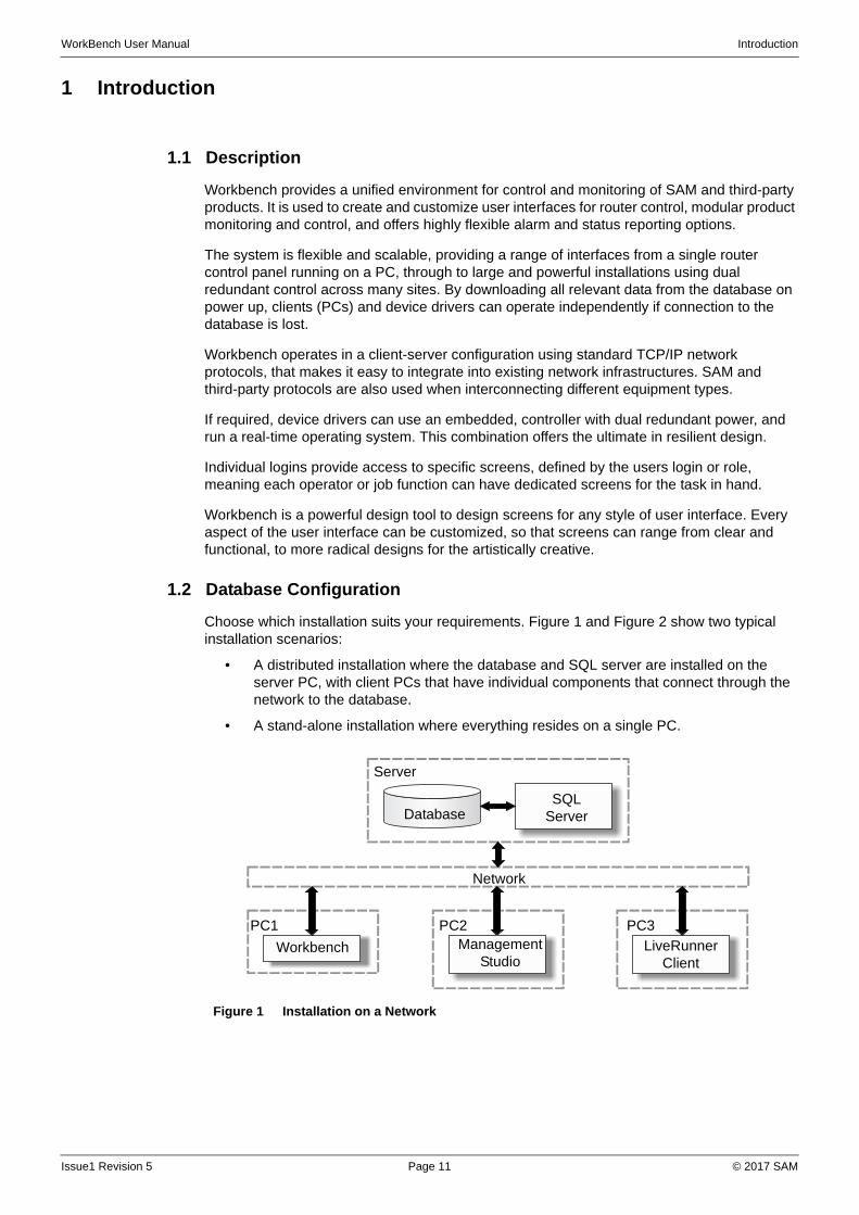
Choose which installation suits your requirements. Figure 1 and Figure 2 show two typical installation scenarios:
• A distributed installation where the database and SQL server are installed on the server PC, with client PCs that have individual components that connect through the network to the database.
• A stand-alone installation where everything resides on a single PC.
Figure 1 Installation on a Network
Workbench Management Studio
LiveRunner Client
DatabaseSQL
Server
Network
Server
PC1 PC2 PC3
Issue1 Revision 5 Page 11 © 2017 SAM
WorkBench User Manual Introduction
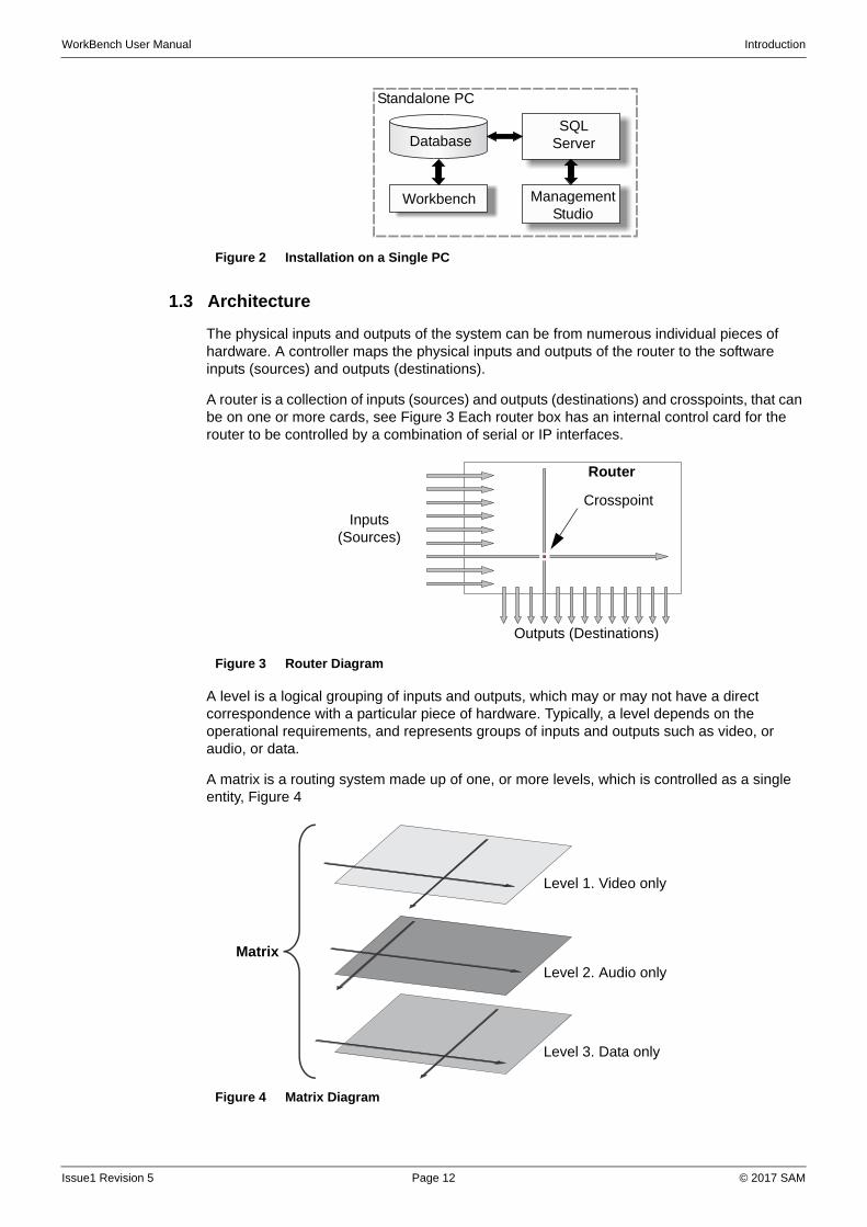
1.3 Architecture
The physical inputs and outputs of the system can be from numerous individual pieces of hardware. A controller maps the physical inputs and outputs of the router to the software inputs (sources) and outputs (destinations).
A router is a collection of inputs (sources) and outputs (destinations) and crosspoints, that can be on one or more cards, see Figure 3 Each router box has an internal control card for the router to be controlled by a combination of serial or IP interfaces.
A level is a logical grouping of inputs and outputs, which may or may not have a direct correspondence with a particular piece of hardware. Typically, a level depends on the operational requirements, and represents groups of inputs and outputs such as video, or audio, or data.
A matrix is a routing system made up of one, or more levels, which is controlled as a single entity, Figure 4
Figure 2 Installation on a Single PC
Standalone PC
DatabaseSQL
Server
Workbench Management Studio
Figure 3 Router Diagram
Figure 4 Matrix Diagram
Router
Inputs (Sources)
Outputs (Destinations)
Crosspoint
Matrix
Level 1. Video only
Level 2. Audio only
Level 3. Data only
Issue1 Revision 5 Page 12 © 2017 SAM
WorkBench User Manual Introduction
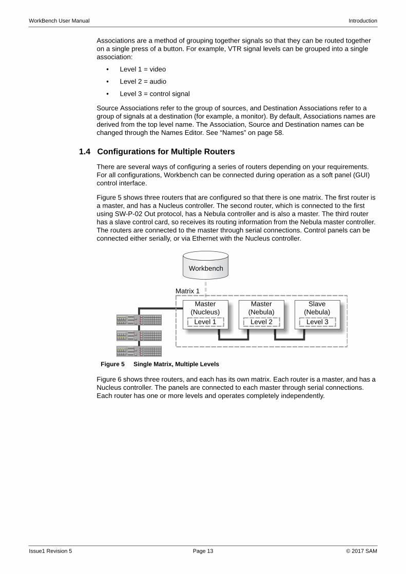
Associations are a method of grouping together signals so that they can be routed together on a single press of a button. For example, VTR signal levels can be grouped into a single association:
• Level 1 = video
• Level 2 = audio
• Level 3 = control signal
Source Associations refer to the group of sources, and Destination Associations refer to a group of signals at a destination (for example, a monitor). By default, Associations names are derived from the top level name. The Association, Source and Destination names can be changed through the Names Editor. See “Names” on page 58.
1.4 Configurations for Multiple Routers
There are several ways of configuring a series of routers depending on your requirements. For all configurations, Workbench can be connected during operation as a soft panel (GUI) control interface.
Figure 5 shows three routers that are configured so that there is one matrix. The first router is a master, and has a Nucleus controller. The second router, which is connected to the first using SW-P-02 Out protocol, has a Nebula controller and is also a master. The third router has a slave control card, so receives its routing information from the Nebula master controller. The routers are connected to the master through serial connections. Control panels can be connected either serially, or via Ethernet with the Nucleus controller.
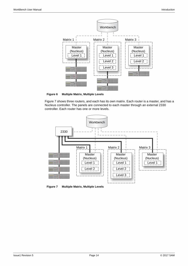
Figure 6 shows three routers, and each has its own matrix. Each router is a master, and has a Nucleus controller. The panels are connected to each master through serial connections. Each router has one or more levels and operates completely independently.
Figure 5 Single Matrix, Multiple Levels
Workbench
Level 1 Level 2 Level 3
Matrix 1
Master (Nucleus)
Master (Nebula)
Slave (Nebula)
Issue1 Revision 5 Page 13 © 2017 SAM
WorkBench User Manual Introduction
Figure 7 shows three routers, and each has its own matrix. Each router is a master, and has a Nucleus controller. The panels are connected to each master through an external 2330 controller. Each router has one or more levels.
Figure 6 Multiple Matrix, Multiple Levels
Figure 7 Multiple Matrix, Multiple Levels
Level 1 Level 1 Level 1
Matrix 1
Master (Nucleus)
Master (Nucleus)
Master (Nucleus)
Matrix 2 Matrix 3
Workbench
Level 2
Level 3
Level 2
Level 1 Level 1 Level 1
Matrix 1
2330
Master (Nucleus)
Master (Nucleus)
Master (Nucleus)
Matrix 2 Matrix 3
Level 2 Level 2
Level 3
Workbench
Issue1 Revision 5 Page 14 © 2017 SAM
WorkBench User Manual Introduction
1.5 Protocols
Workbench control systems employ a large number of native and third-party protocols. The following SAM protocols are used in Workbench systems:
• DCCP — The Device Configuration and Control Protocol is the primary IP protocol used to configure and control hardware from Workbench.
• General Switcher (SW-P-02) — Available on RS232, RS422, or Ethernet in most routers, and is used by 2330 serial router ports for direct control of a router by numerical source and destination. Also router status can be interrogated for missing or faulty modules.
• General Remote (SW-P-08) — Available on RS232, RS422, or Ethernet for communication with a control system, or interfacing with automation (third party in some cases). Allows interrogation of source and destination names, and supports all on-line editor messages and diagnostics.
• Multidrop (SW-P0-6) — RS422 for communication with a control system allowing up to 16 devices from one multi-drop string. A range of BPX, Dial-up and LCD panels can be connected to the system. UMDs are not directly supported.
Issue1 Revision 5 Page 15 © 2017 SAM

WorkBench User Manual Introduction
Issue1 Revision 5 Page 16 © 2017 SAM
WorkBench User Manual Installation
2 Installation
2.1 System Requirements
The Workbench software can run with any screen resolution. However, a resolution of 1920 x 1080 is recommended for Run mode and screen design, and a minimum of 1280 x 1024 for Workbench general configuration.
27BSpecification:
• A PC running MS Windows 7 64-bit (Windows 7 32-bit and XP SP3 or higher 32-bit or 64-bit are also supported)
• A multi-core processor (>2.1 GHz)
• 1 GB RAM minimum (>2 GB RAM recommended)
• Support for DirectX 9 graphics with a WDDM driver, 128 MB of graphics memory (minimum), Pixel Shader 2.0 and 32 bits per pixel
System performance is dependent on the PC’s available resources. The PC should be as “clean” as possible of other running processes.
2.1.1 Minimum Installation Requirements
For a distributed installation, the minimum installation requirement consists of the mandatory items and the LiveRunner component, see Table 1
For a standalone installation, the minimum installation consists of the mandatory items and the SQL Server Express component.
2.2 Install Workbench
1. If upgrading, ensure that no Workbench components are running, for example, LiveRunner.
2. Insert the Workbench DVD into the CD-ROM drive. The installation application starts automatically. If it does not, browse to the installation CD-ROM and click WorkbenchInstaller.exe.
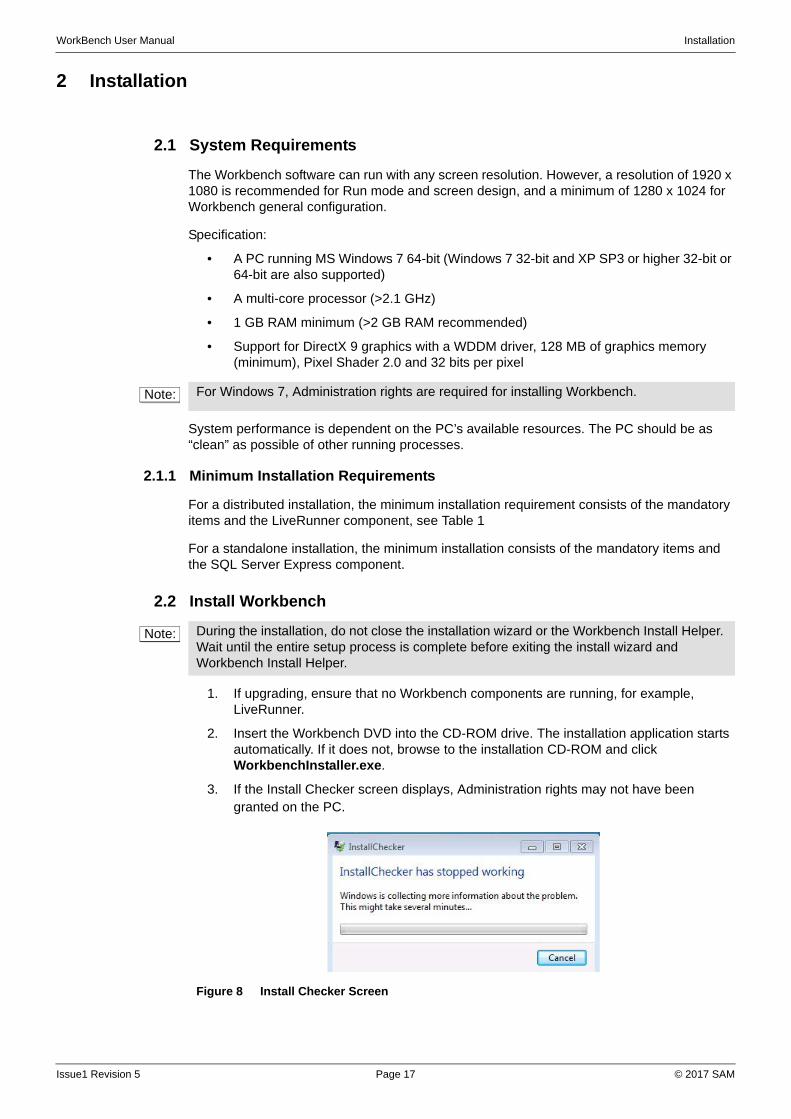
3. If the Install Checker screen displays, Administration rights may not have been granted on the PC.
Note: For Windows 7, Administration rights are required for installing Workbench.
Note: During the installation, do not close the installation wizard or the Workbench Install Helper. Wait until the entire setup process is complete before exiting the install wizard and Workbench Install Helper.
Figure 8 Install Checker Screen
Issue1 Revision 5 Page 17 © 2017 SAM
WorkBench User Manual Installation
To run the Configuration Helper, open:
Start | All Programs | Snell | MCM | Utilities | Configuration Helper
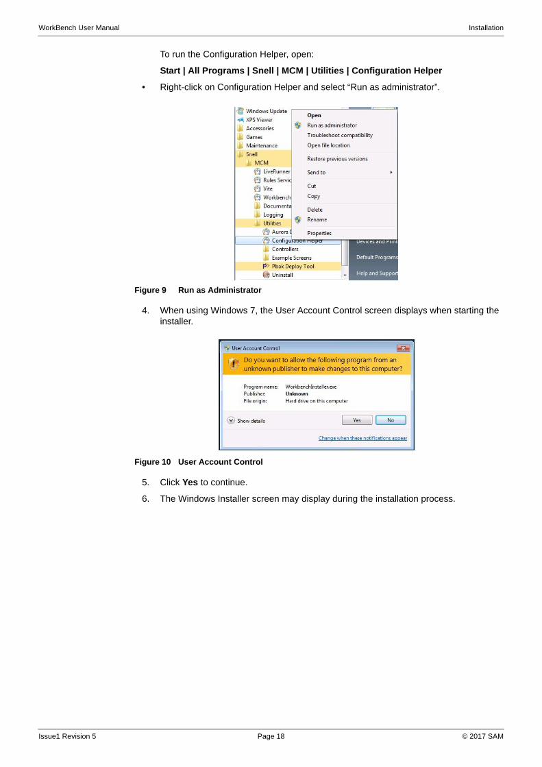
• Right-click on Configuration Helper and select “Run as administrator”.
4. When using Windows 7, the User Account Control screen displays when starting the installer.
5. Click Yes to continue.
6. The Windows Installer screen may display during the installation process.
Figure 9 Run as Administrator
Figure 10 User Account Control
Issue1 Revision 5 Page 18 © 2017 SAM

WorkBench User Manual Installation
7. Click OK. The installation continues.
8. The end user license agreement (EULA) displays.
9. Read through the license, and click I Agree.
Figure 11 Windows Installer Screen
Figure 12 License Agreement
Issue1 Revision 5 Page 19 © 2017 SAM

WorkBench User Manual Installation
10. The Choose Components screen displays.
11. Select the Workbench components to install and clear those that are not required for installation. Table 1 lists the available options.
Figure 13 Choose Components
Note: Greyed-out ( ) items are mandatory. The installer checks to see whether the item is already present, and only installs it if it is not found.
Issue1 Revision 5 Page 20 © 2017 SAM
WorkBench User Manual Installation
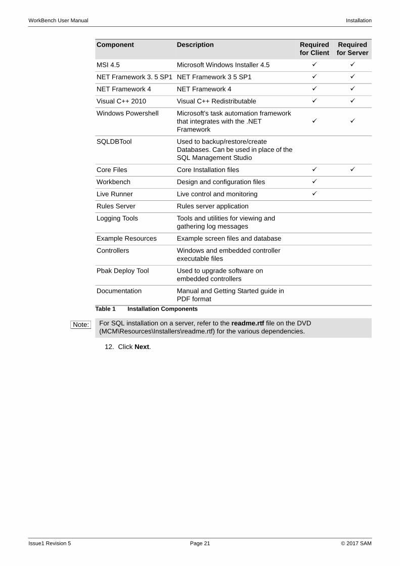
12. Click Next.
Component Description Required for Client
Required for Server
MSI 4.5 Microsoft Windows Installer 4.5
NET Framework 3. 5 SP1 NET Framework 3 5 SP1
NET Framework 4 NET Framework 4
Visual C++ 2010 Visual C++ Redistributable
Windows Powershell Microsoft's task automation framework that integrates with the .NET Framework
SQLDBTool Used to backup/restore/create Databases. Can be used in place of the SQL Management Studio
Core Files Core Installation files
Workbench Design and configuration files
Live Runner Live control and monitoring
Rules Server Rules server application
Logging Tools Tools and utilities for viewing and gathering log messages
Example Resources Example screen files and database
Controllers Windows and embedded controller executable files
Pbak Deploy Tool Used to upgrade software on embedded controllers
Documentation Manual and Getting Started guide in PDF format
Table 1 Installation Components
Note: For SQL installation on a server, refer to the readme.rtf file on the DVD (MCM\Resources\Installers\readme.rtf) for the various dependencies.
Issue1 Revision 5 Page 21 © 2017 SAM
WorkBench User Manual Installation
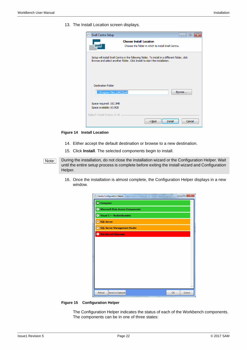
13. The Install Location screen displays.
14. Either accept the default destination or browse to a new destination.
15. Click Install. The selected components begin to install.
16. Once the installation is almost complete, the Configuration Helper displays in a new window.
The Configuration Helper indicates the status of each of the Workbench components. The components can be in one of three states:
Figure 14 Install Location
Note: During the installation, do not close the installation wizard or the Configuration Helper. Wait until the entire setup process is complete before exiting the install wizard and Configuration Helper.
Figure 15 Configuration Helper
Issue1 Revision 5 Page 22 © 2017 SAM
WorkBench User Manual Installation
• Green: The component installed correctly.
• Orange: Optional item that has not been installed. (If the Computer component is Orange it indicates that the screen resolution is not high enough).
• Red (yellow during update): Required by Workbench but not yet installed.
17. If the Configuration Helper indicates that all components are installed correctly (green), click OK. The Configuration Helper screen closes, and the Completing installation screen displays.
If the Configuration Helper displays components that have not installed (red) these need to be manually installed before continuing. See Manually Installing Components on page 23.
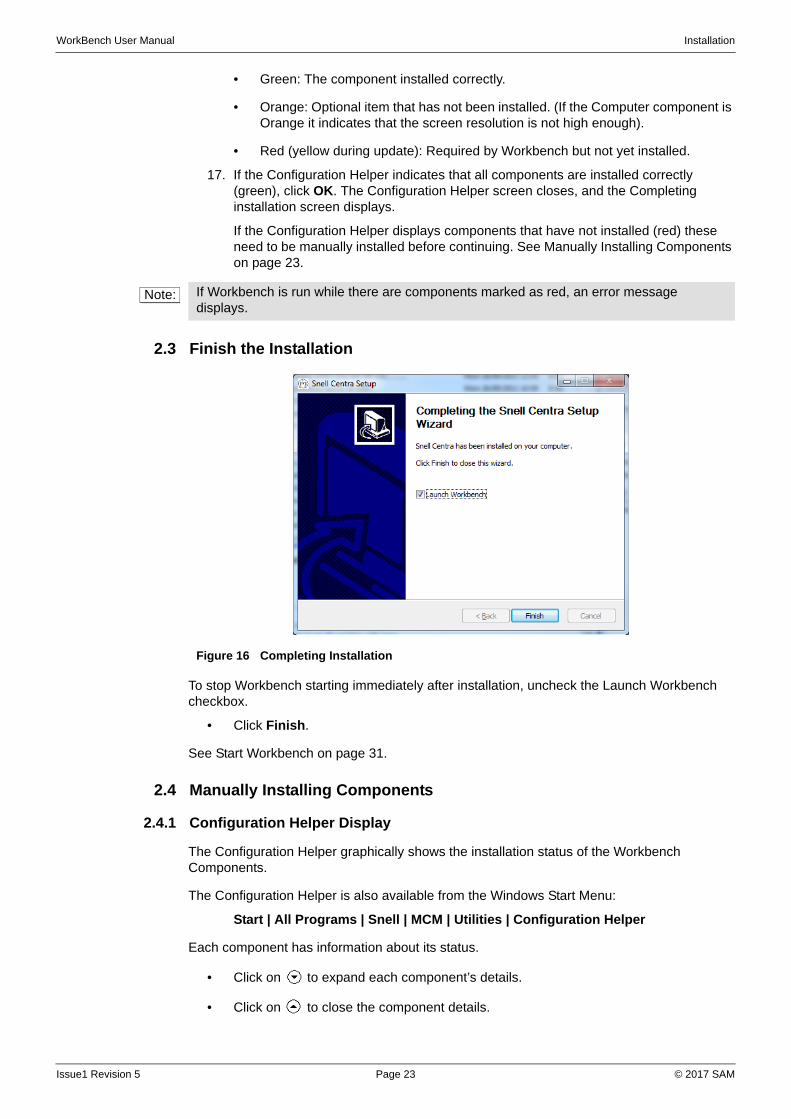
2.3 Finish the Installation
To stop Workbench starting immediately after installation, uncheck the Launch Workbench checkbox.
• Click Finish.
See Start Workbench on page 31.
2.4 Manually Installing Components
2.4.1 Configuration Helper Display
The Configuration Helper graphically shows the installation status of the Workbench Components.
The Configuration Helper is also available from the Windows Start Menu:
Start | All Programs | Snell | MCM | Utilities | Configuration Helper
Each component has information about its status.
• Click on to expand each component’s details.
• Click on to close the component details.
Note: If Workbench is run while there are components marked as red, an error message displays.
Figure 16 Completing Installation
Issue1 Revision 5 Page 23 © 2017 SAM

WorkBench User Manual Installation
The different components are listed in Table 2
Issue1 Revision 5 Page 24 © 2017 SAM
WorkBench User Manual Installation
2.4.2 Support
If problems occur with the installation at any time contact customer support www.s-a-m.com/support/247-support/).
• Click Copy to Clipboard, and paste the current screen information into the email.
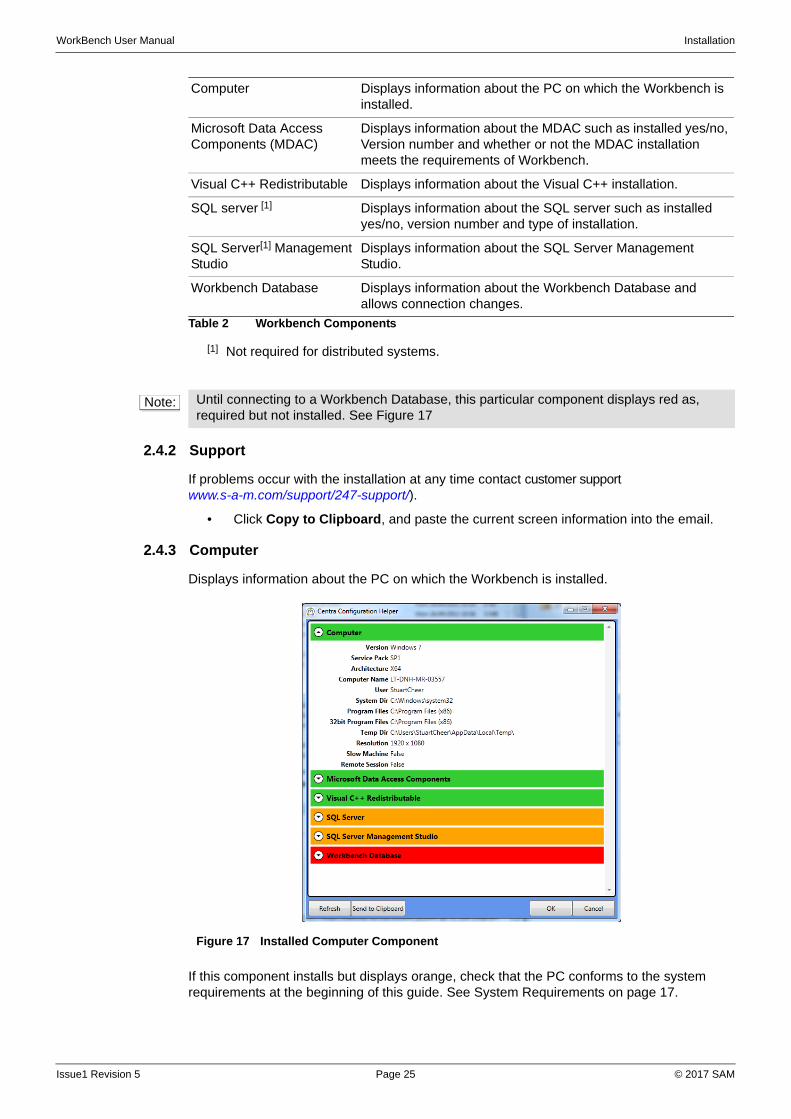
2.4.3 Computer
Displays information about the PC on which the Workbench is installed.
If this component installs but displays orange, check that the PC conforms to the system requirements at the beginning of this guide. See System Requirements on page 17.
.
Computer Displays information about the PC on which the Workbench is installed.
Microsoft Data Access Components (MDAC)
Displays information about the MDAC such as installed yes/no, Version number and whether or not the MDAC installation meets the requirements of Workbench.
Visual C++ Redistributable Displays information about the Visual C++ installation.
SQL server [1]
[1] Not required for distributed systems.
Displays information about the SQL server such as installed yes/no, version number and type of installation.
SQL Server[1] Management Studio
Displays information about the SQL Server Management Studio.
Workbench Database Displays information about the Workbench Database and allows connection changes.
Table 2 Workbench Components
Note: Until connecting to a Workbench Database, this particular component displays red as, required but not installed. See Figure 17
Figure 17 Installed Computer Component
Issue1 Revision 5 Page 25 © 2017 SAM
WorkBench User Manual Installation
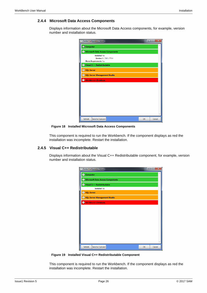
2.4.4 Microsoft Data Access Components
Displays information about the Microsoft Data Access components, for example, version number and installation status.
This component is required to run the Workbench. If the component displays as red the installation was incomplete. Restart the installation.
2.4.5 Visual C++ Redistributable
Displays information about the Visual C++ Redistributable component, for example, version number and installation status.
This component is required to run the Workbench. If the component displays as red the installation was incomplete. Restart the installation.
Figure 18 Installed Microsoft Data Access Components
Figure 19 Installed Visual C++ Redistributable Component
Issue1 Revision 5 Page 26 © 2017 SAM
WorkBench User Manual Installation
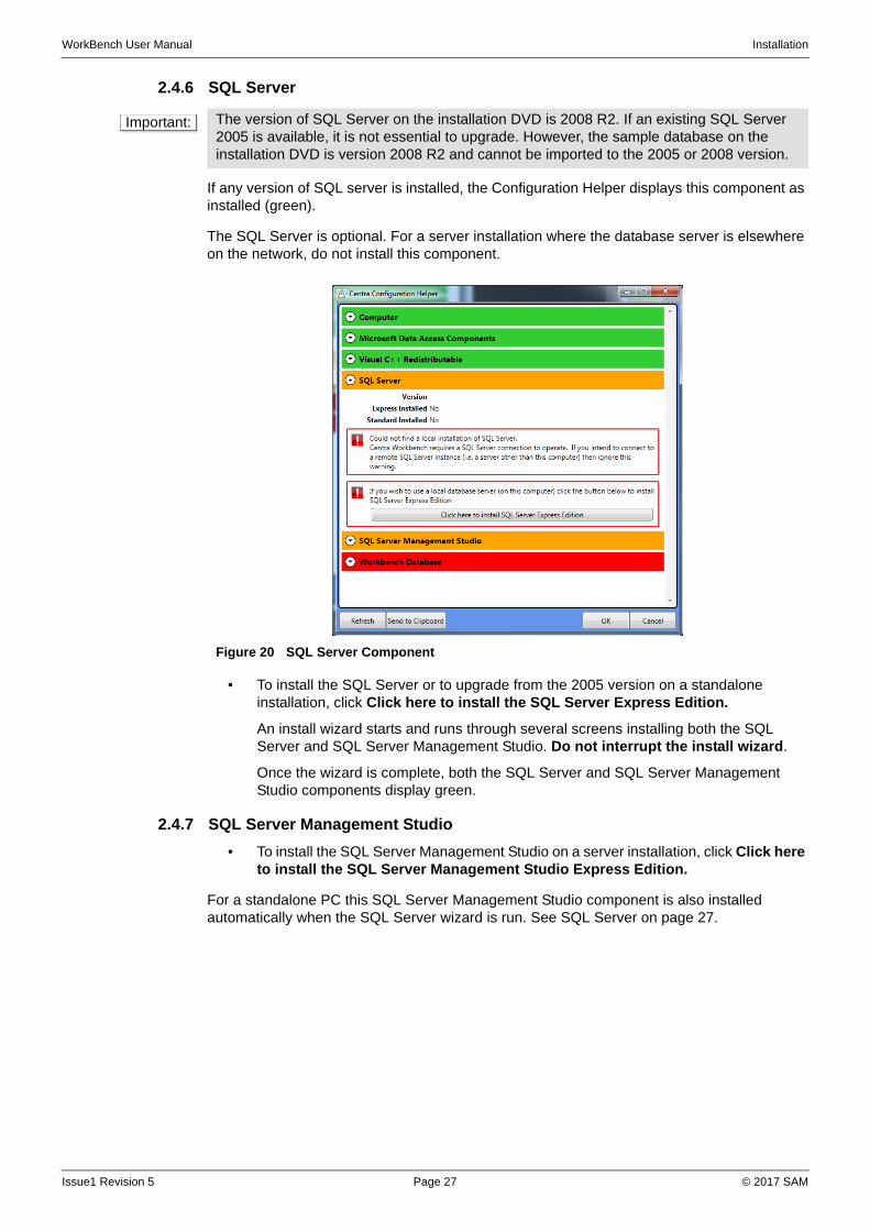
2.4.6 SQL Server
If any version of SQL server is installed, the Configuration Helper displays this component as installed (green).
The SQL Server is optional. For a server installation where the database server is elsewhere on the network, do not install this component.
• To install the SQL Server or to upgrade from the 2005 version on a standalone installation, click Click here to install the SQL Server Express Edition.
An install wizard starts and runs through several screens installing both the SQL Server and SQL Server Management Studio. Do not interrupt the install wizard.
Once the wizard is complete, both the SQL Server and SQL Server Management Studio components display green.
2.4.7 SQL Server Management Studio
• To install the SQL Server Management Studio on a server installation, click Click here to install the SQL Server Management Studio Express Edition.
For a standalone PC this SQL Server Management Studio component is also installed automatically when the SQL Server wizard is run. See SQL Server on page 27.
Important: The version of SQL Server on the installation DVD is 2008 R2. If an existing SQL Server 2005 is available, it is not essential to upgrade. However, the sample database on the installation DVD is version 2008 R2 and cannot be imported to the 2005 or 2008 version.
Figure 20 SQL Server Component
Issue1 Revision 5 Page 27 © 2017 SAM
WorkBench User Manual Installation
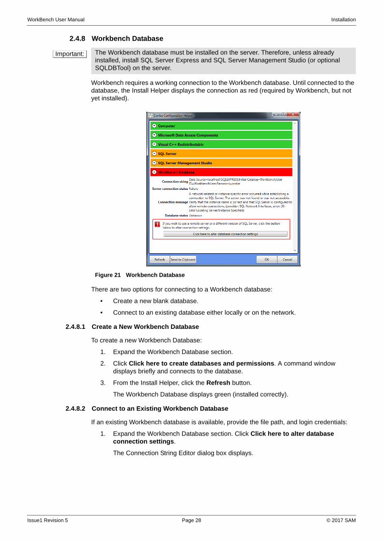
2.4.8 Workbench Database
Workbench requires a working connection to the Workbench database. Until connected to the database, the Install Helper displays the connection as red (required by Workbench, but not yet installed).
There are two options for connecting to a Workbench database:
• Create a new blank database.
• Connect to an existing database either locally or on the network.
2.4.8.1 Create a New Workbench Database
To create a new Workbench Database:
1. Expand the Workbench Database section.
2. Click Click here to create databases and permissions. A command window displays briefly and connects to the database.
3. From the Install Helper, click the Refresh button.
The Workbench Database displays green (installed correctly).
2.4.8.2 Connect to an Existing Workbench Database
If an existing Workbench database is available, provide the file path, and login credentials:
1. Expand the Workbench Database section. Click Click here to alter database connection settings.
The Connection String Editor dialog box displays.
Important: The Workbench database must be installed on the server. Therefore, unless already installed, install SQL Server Express and SQL Server Management Studio (or optional SQLDBTool) on the server.
Figure 21 Workbench Database
Issue1 Revision 5 Page 28 © 2017 SAM
WorkBench User Manual Installation
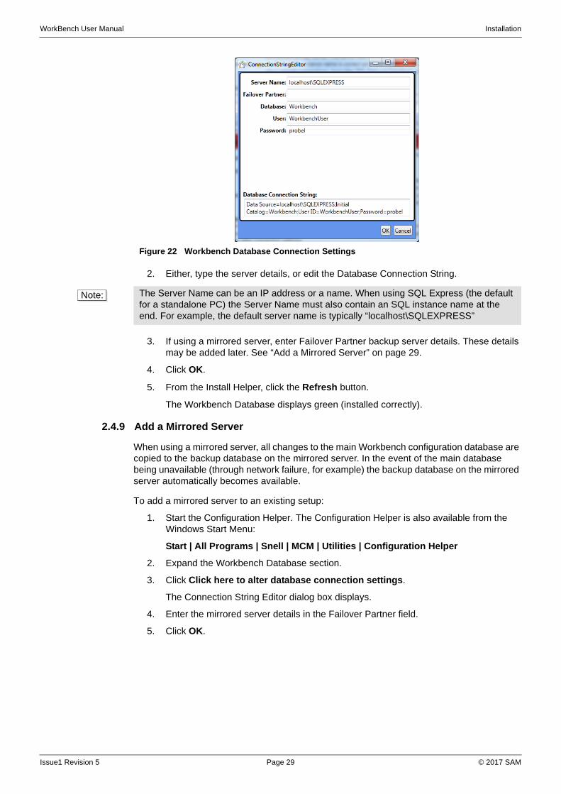
2. Either, type the server details, or edit the Database Connection String.
3. If using a mirrored server, enter Failover Partner backup server details. These details may be added later. See “Add a Mirrored Server” on page 29.
4. Click OK.
5. From the Install Helper, click the Refresh button.
The Workbench Database displays green (installed correctly).
2.4.9 Add a Mirrored Server
When using a mirrored server, all changes to the main Workbench configuration database are copied to the backup database on the mirrored server. In the event of the main database being unavailable (through network failure, for example) the backup database on the mirrored server automatically becomes available.
To add a mirrored server to an existing setup:
1. Start the Configuration Helper. The Configuration Helper is also available from the Windows Start Menu:
Start | All Programs | Snell | MCM | Utilities | Configuration Helper
2. Expand the Workbench Database section.
3. Click Click here to alter database connection settings.
The Connection String Editor dialog box displays.
4. Enter the mirrored server details in the Failover Partner field.
5. Click OK.
Figure 22 Workbench Database Connection Settings
Note: The Server Name can be an IP address or a name. When using SQL Express (the default for a standalone PC) the Server Name must also contain an SQL instance name at the end. For example, the default server name is typically “localhost\SQLEXPRESS”
Issue1 Revision 5 Page 29 © 2017 SAM
WorkBench User Manual Installation
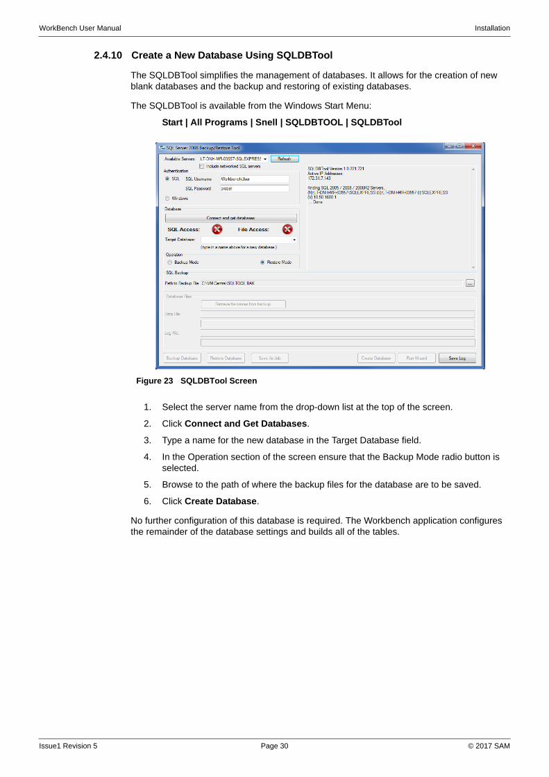
2.4.10 Create a New Database Using SQLDBTool
The SQLDBTool simplifies the management of databases. It allows for the creation of new blank databases and the backup and restoring of existing databases.
The SQLDBTool is available from the Windows Start Menu:
Start | All Programs | Snell | SQLDBTOOL | SQLDBTool
1. Select the server name from the drop-down list at the top of the screen.
2. Click Connect and Get Databases.
3. Type a name for the new database in the Target Database field.
4. In the Operation section of the screen ensure that the Backup Mode radio button is selected.
5. Browse to the path of where the backup files for the database are to be saved.
6. Click Create Database.
No further configuration of this database is required. The Workbench application configures the remainder of the database settings and builds all of the tables.
Figure 23 SQLDBTool Screen
Issue1 Revision 5 Page 30 © 2017 SAM
WorkBench User Manual Installation
2.4.11 Create a Blank Database Using SQLMS
To create a new database SQL Server Express and SQL Server Management Studio must be installed on the server.
To create a new database:
1. Start SQL Server Management Studio. Confirm the server name and login credentials.
2. Right-click the databases node in the object explorer and select New Database.
3. Type the name of the database in the Database name field (the default is Workbench).
4. Click OK.
No further configuration of this database is required. The Workbench application configures the remainder of the database settings and builds all of the tables.
2.4.12 Install Sample Databases
The sample databases each have several example controllers and hardware panels, and are on the installation DVD. To install the sample database:
1. Browse to the installation CD-ROM and open the Nucleus Default Configurations folder. The example databases are in .zip folders.
2. Right-click the required .zip file and select Extract All… the Extraction Wizard displays. Click Next.
3. Browse to an appropriate location for the files, and click Next. A .bak file is extracted to the selected location. Click Finish.
4. Make sure that Workbench is NOT open.
5. Open SQL server management express and connect to the server.
6. Expand the Databases folder. Right-click on the Workbench database and select Tasks | Restore | Database.
7. In the Source for restore section, select From device and click the (browse) button. The Specify Backup dialog box displays, click Add.
8. Locate the .bak file, select it and then click OK.
9. In the Specify Backup dialog box, click OK.
10. Select the file from the Select the backup sets to restore section of the Restore Database dialog box.
11. In the Select a page section, click Options. Select Overwrite the existing database and Leave the database ready to use…(RESTORE WITH RECOVERY).
12. Edit the paths and filenames from the default, accordingly, if required.
13. Click OK, and close SQL server management express. The first time that Workbench is started, update the database.
2.5 Start Workbench
When the Install Helper shows that all the required components have installed correctly, start Workbench.
Important: The sample databases on the installation DVD are SQL version 2008 R2 and cannot be imported to 2005. To install the Workbench databases, upgrade to SQL Server 2008 R2.
When a Workbench database is converted to SQL Server 2008 R2, it is not possible to revert back to SQL Server 2005. Therefore, if using an existing version of the Workbench database, make a full backup before upgrading.
Issue1 Revision 5 Page 31 © 2017 SAM
WorkBench User Manual Installation
To start the Workbench, do one of the following:
• Double-click the Workbench icon on the desktop.
• Start the program from the Windows Start menu.
The path to Workbench in the Start menu is:
Start | All Programs | Snell | MCM | Workbench
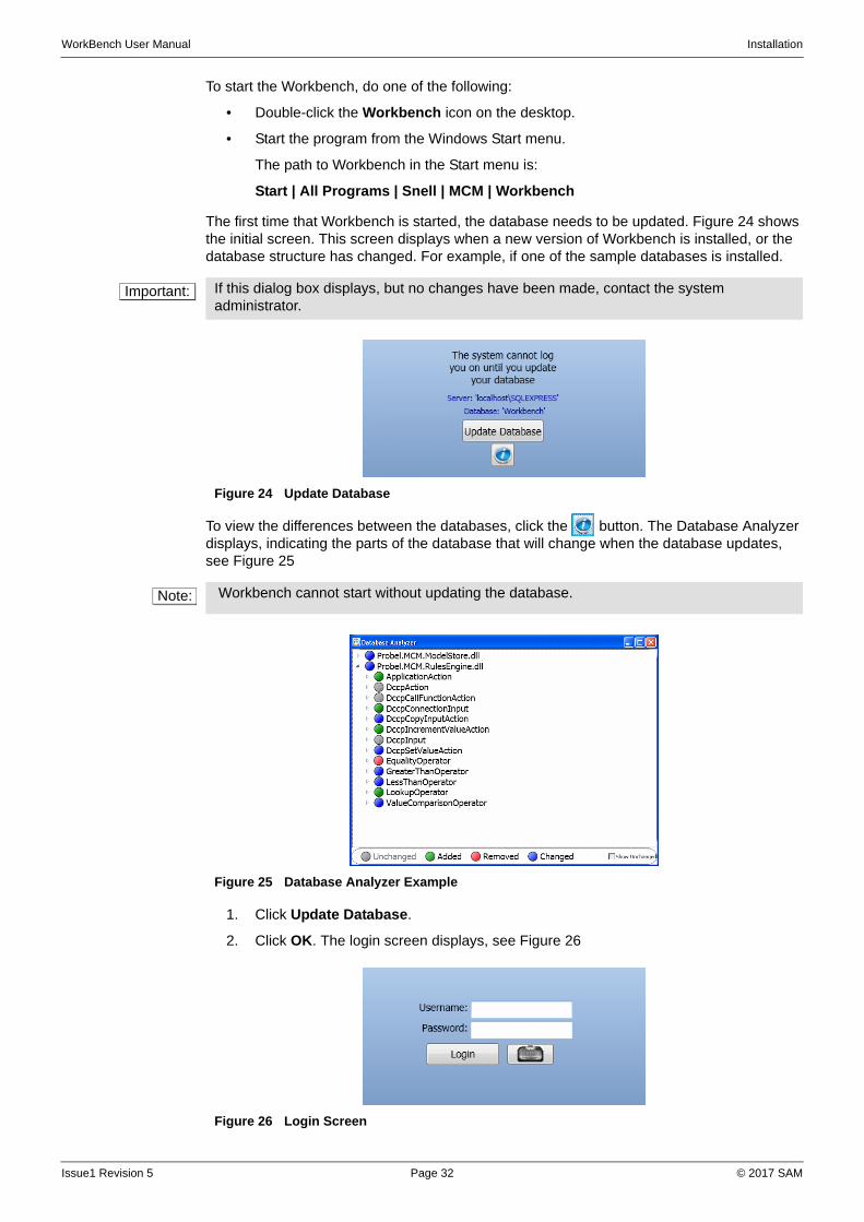
The first time that Workbench is started, the database needs to be updated. Figure 24 shows the initial screen. This screen displays when a new version of Workbench is installed, or the database structure has changed. For example, if one of the sample databases is installed.
To view the differences between the databases, click the button. The Database Analyzer displays, indicating the parts of the database that will change when the database updates, see Figure 25
1. Click Update Database.
2. Click OK. The login screen displays, see Figure 26
Important: If this dialog box displays, but no changes have been made, contact the system administrator.
Figure 24 Update Database
Note: Workbench cannot start without updating the database.
Figure 25 Database Analyzer Example
Figure 26 Login Screen
Issue1 Revision 5 Page 32 © 2017 SAM
WorkBench User Manual Installation
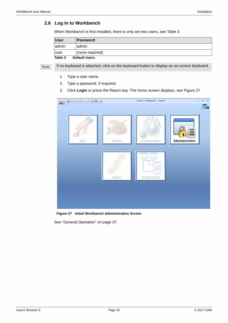
2.6 Log In to Workbench
When Workbench is first installed, there is only are two users, see Table 3
1. Type a user name.
2. Type a password, if required.
3. Click Login or press the Return key. The home screen displays, see Figure 27
See “General Operation” on page 37.
User Password
admin admin
user (none required)Table 3 Default Users
Note: If no keyboard is attached, click on the keyboard button to display an on-screen keyboard.
Figure 27 Initial Workbench Administration Screen
Issue1 Revision 5 Page 33 © 2017 SAM
WorkBench User Manual Installation
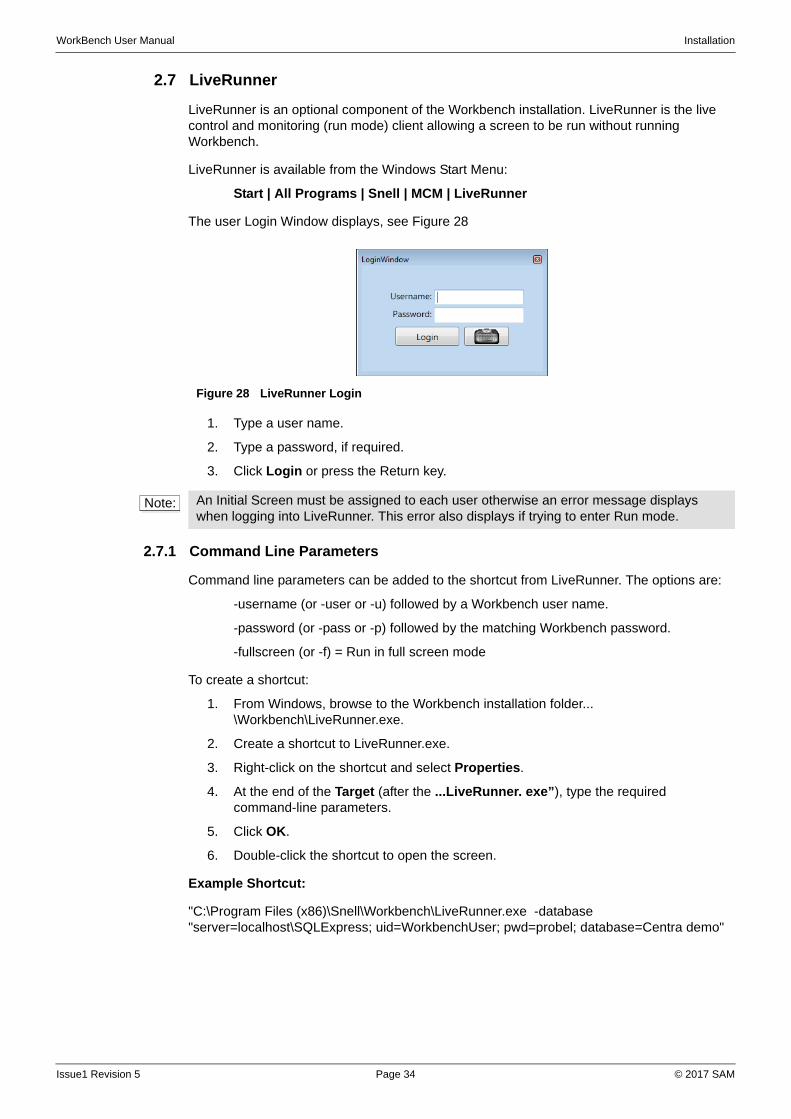
2.7 LiveRunner
LiveRunner is an optional component of the Workbench installation. LiveRunner is the live control and monitoring (run mode) client allowing a screen to be run without running Workbench.
LiveRunner is available from the Windows Start Menu:
Start | All Programs | Snell | MCM | LiveRunner
The user Login Window displays, see Figure 28
1. Type a user name.
2. Type a password, if required.
3. Click Login or press the Return key.
2.7.1 Command Line Parameters
Command line parameters can be added to the shortcut from LiveRunner. The options are:
-username (or -user or -u) followed by a Workbench user name.
-password (or -pass or -p) followed by the matching Workbench password.
-fullscreen (or -f) = Run in full screen mode
To create a shortcut:
1. From Windows, browse to the Workbench installation folder... \Workbench\LiveRunner.exe.
2. Create a shortcut to LiveRunner.exe.
3. Right-click on the shortcut and select Properties.
4. At the end of the Target (after the ...LiveRunner. exe”), type the required command-line parameters.
5. Click OK.
6. Double-click the shortcut to open the screen.
Example Shortcut:
"C:\Program Files (x86)\Snell\Workbench\LiveRunner.exe -database "server=localhost\SQLExpress; uid=WorkbenchUser; pwd=probel; database=Centra demo"
Figure 28 LiveRunner Login
Note: An Initial Screen must be assigned to each user otherwise an error message displays when logging into LiveRunner. This error also displays if trying to enter Run mode.
Issue1 Revision 5 Page 34 © 2017 SAM
WorkBench User Manual Installation
2.8 Pbak DeployTool
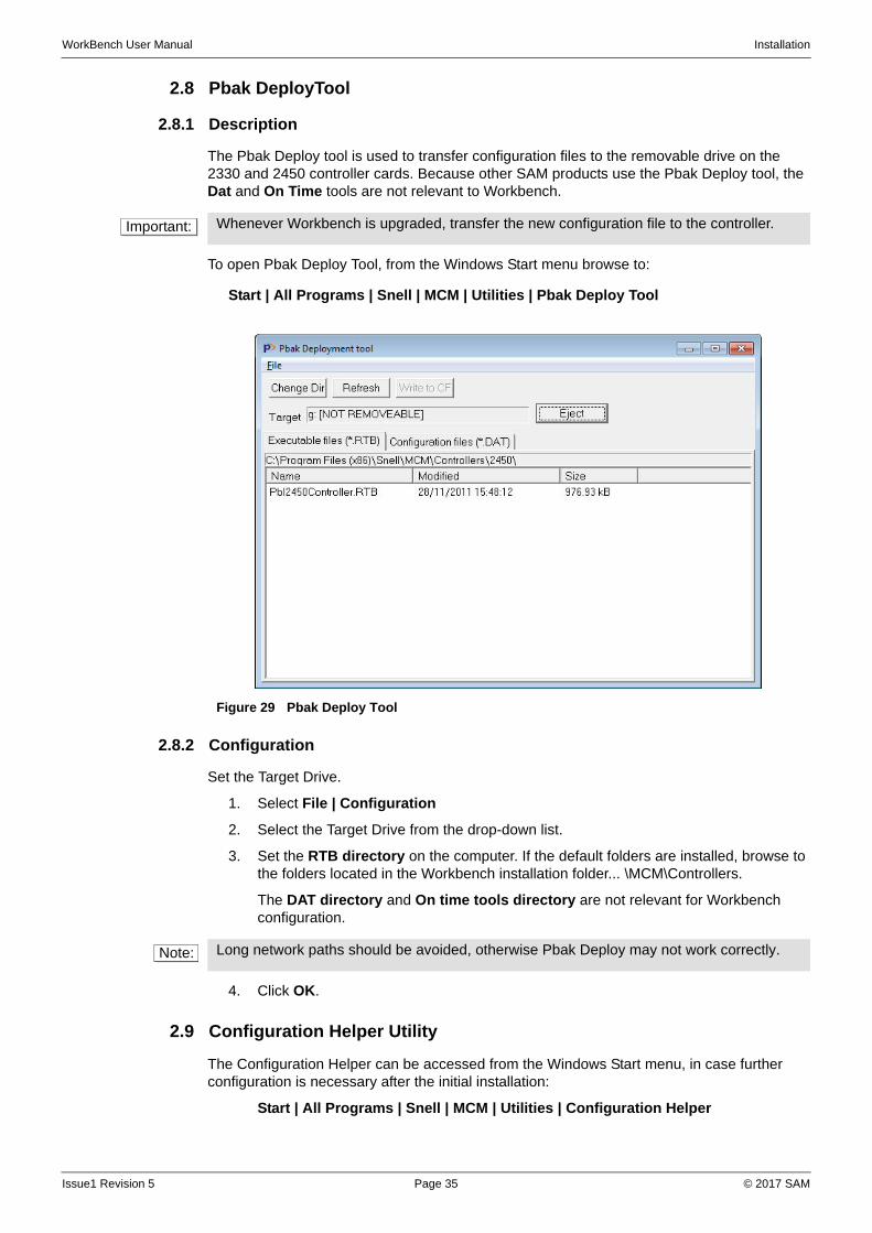
2.8.1 Description
The Pbak Deploy tool is used to transfer configuration files to the removable drive on the 2330 and 2450 controller cards. Because other SAM products use the Pbak Deploy tool, the Dat and On Time tools are not relevant to Workbench.
To open Pbak Deploy Tool, from the Windows Start menu browse to:
Start | All Programs | Snell | MCM | Utilities | Pbak Deploy Tool
2.8.2 Configuration
Set the Target Drive.
1. Select File | Configuration
2. Select the Target Drive from the drop-down list.
3. Set the RTB directory on the computer. If the default folders are installed, browse to the folders located in the Workbench installation folder... \MCM\Controllers.
The DAT directory and On time tools directory are not relevant for Workbench configuration.
4. Click OK.
2.9 Configuration Helper Utility
The Configuration Helper can be accessed from the Windows Start menu, in case further configuration is necessary after the initial installation:
Start | All Programs | Snell | MCM | Utilities | Configuration Helper
Important: Whenever Workbench is upgraded, transfer the new configuration file to the controller.
Figure 29 Pbak Deploy Tool
Note: Long network paths should be avoided, otherwise Pbak Deploy may not work correctly.
Issue1 Revision 5 Page 35 © 2017 SAM

WorkBench User Manual Installation
Issue1 Revision 5 Page 36 © 2017 SAM
WorkBench User Manual General Operation
3 General Operation
3.1 Screen Layout
3.1.1 Home Screen
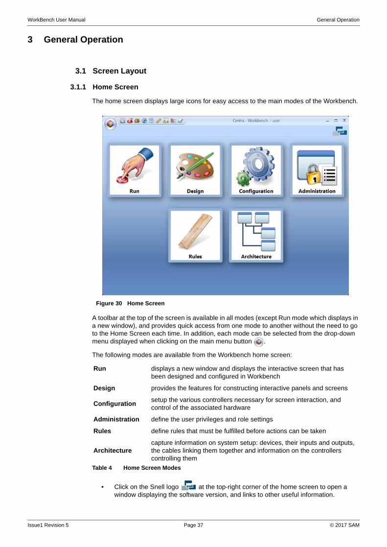
The home screen displays large icons for easy access to the main modes of the Workbench.
A toolbar at the top of the screen is available in all modes (except Run mode which displays in a new window), and provides quick access from one mode to another without the need to go to the Home Screen each time. In addition, each mode can be selected from the drop-down menu displayed when clicking on the main menu button .
The following modes are available from the Workbench home screen:
• Click on the Snell logo at the top-right corner of the home screen to open a window displaying the software version, and links to other useful information.
Figure 30 Home Screen
Run displays a new window and displays the interactive screen that has been designed and configured in Workbench
Design provides the features for constructing interactive panels and screens
Configurationsetup the various controllers necessary for screen interaction, and control of the associated hardware
Administration define the user privileges and role settings
Rules define rules that must be fulfilled before actions can be taken
Architecturecapture information on system setup: devices, their inputs and outputs, the cables linking them together and information on the controllers controlling them
Table 4 Home Screen Modes
Issue1 Revision 5 Page 37 © 2017 SAM
WorkBench User Manual General Operation
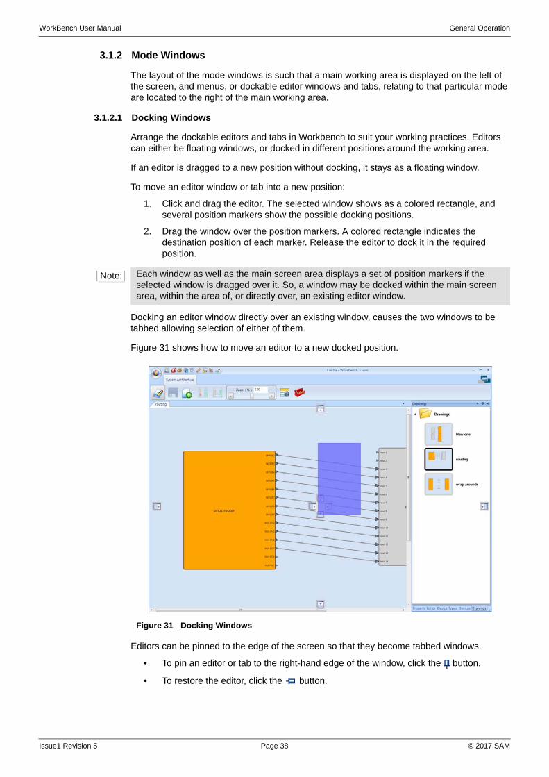
3.1.2 Mode Windows
The layout of the mode windows is such that a main working area is displayed on the left of the screen, and menus, or dockable editor windows and tabs, relating to that particular mode are located to the right of the main working area.
3.1.2.1 Docking Windows
Arrange the dockable editors and tabs in Workbench to suit your working practices. Editors can either be floating windows, or docked in different positions around the working area.
If an editor is dragged to a new position without docking, it stays as a floating window.
To move an editor window or tab into a new position:
1. Click and drag the editor. The selected window shows as a colored rectangle, and several position markers show the possible docking positions.
2. Drag the window over the position markers. A colored rectangle indicates the destination position of each marker. Release the editor to dock it in the required position.
Docking an editor window directly over an existing window, causes the two windows to be tabbed allowing selection of either of them.
Figure 31 shows how to move an editor to a new docked position.
Editors can be pinned to the edge of the screen so that they become tabbed windows.
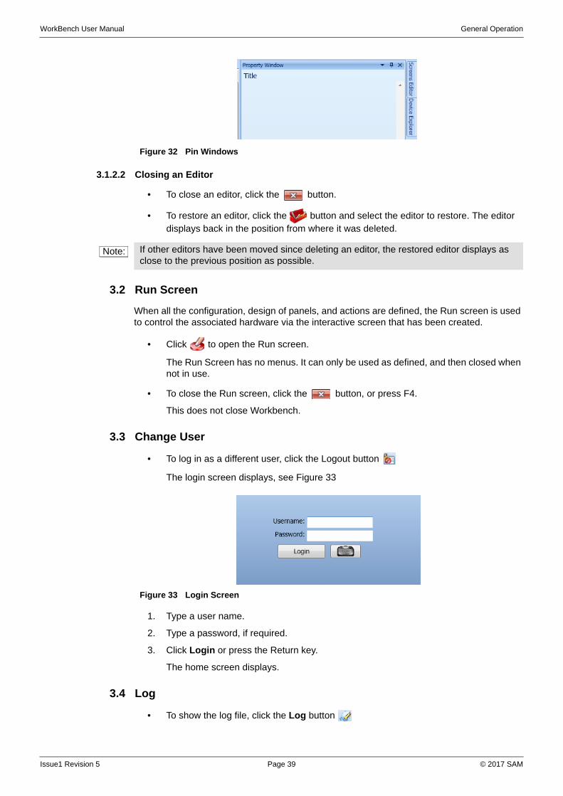
• To pin an editor or tab to the right-hand edge of the window, click the button.
• To restore the editor, click the button.
Note: Each window as well as the main screen area displays a set of position markers if the selected window is dragged over it. So, a window may be docked within the main screen area, within the area of, or directly over, an existing editor window.
Figure 31 Docking Windows
Issue1 Revision 5 Page 38 © 2017 SAM
WorkBench User Manual General Operation
3.1.2.2 Closing an Editor
• To close an editor, click the button.
• To restore an editor, click the button and select the editor to restore. The editor displays back in the position from where it was deleted.
3.2 Run Screen
When all the configuration, design of panels, and actions are defined, the Run screen is used to control the associated hardware via the interactive screen that has been created.
• Click to open the Run screen.
The Run Screen has no menus. It can only be used as defined, and then closed when not in use.
• To close the Run screen, click the button, or press F4.
This does not close Workbench.
3.3 Change User
• To log in as a different user, click the Logout button
The login screen displays, see Figure 33
1. Type a user name.
2. Type a password, if required.
3. Click Login or press the Return key.
The home screen displays.
3.4 Log
• To show the log file, click the Log button
Figure 32 Pin Windows
Note: If other editors have been moved since deleting an editor, the restored editor displays as close to the previous position as possible.
Figure 33 Login Screen
Issue1 Revision 5 Page 39 © 2017 SAM
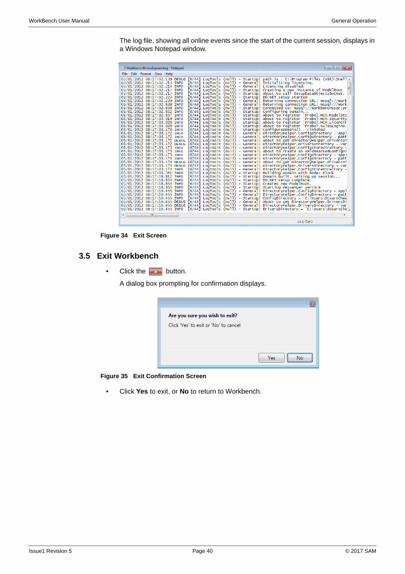
WorkBench User Manual General Operation
The log file, showing all online events since the start of the current session, displays in a Windows Notepad window.
3.5 Exit Workbench
• Click the button.
A dialog box prompting for confirmation displays.
• Click Yes to exit, or No to return to Workbench.
Figure 34 Exit Screen
Figure 35 Exit Confirmation Screen
Issue1 Revision 5 Page 40 © 2017 SAM
WorkBench User Manual Administration
4 Administration
4.1 Description
Administration of Workbench: how to add new users, roles, and permissions. Users belong to groups based upon roles, which are assigned permissions that support their operational needs. For example, access for all control operators, or engineers may be grouped together.
• A Role defines the functions of a group of users.
• A User defines a system user belonging to one or more roles.
When Workbench is first installed, there are two users, see Table 5
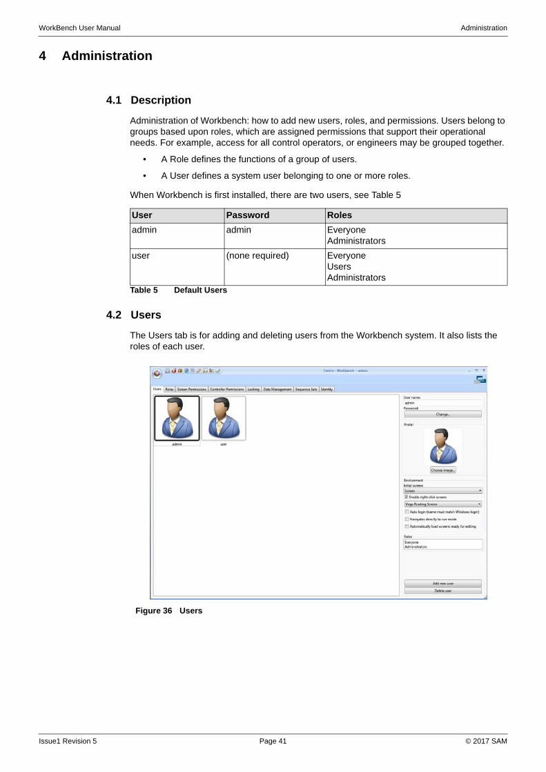
4.2 Users
The Users tab is for adding and deleting users from the Workbench system. It also lists the roles of each user.
User Password Roles
admin admin EveryoneAdministrators
user (none required) EveryoneUsersAdministrators
Table 5 Default Users
Figure 36 Users
Issue1 Revision 5 Page 41 © 2017 SAM

WorkBench User Manual Administration
4.2.1 Add a New User
To add a new user:
1. From the Home screen or menu, click Administration.
2. If it is not already displayed, click the Users tab.
3. Click Add new user. A new user icon is added to the list of users.
4. In the User Name field, type a user name (the user name is not case-sensitive).
Set a new password:
1. Click the Change button. A Change Password dialog box displays. In the Password field, type a password, and then type it again in the Confirm field. The passwords typed in the two fields must be identical. Passwords are case-sensitive. Blank passwords are allowed, but are not recommended. Click OK.
2. If required, select an Avatar. This is an image that represents the user. Click the Choose image button, and browse to the image.
3. Select an Initial screen. When the user logs on to Workbench, and selects Run, this is the screen that displays. See “Screens Editor” on page 117.
A second screen may be setup such that it runs on a right-click of the mouse in run mode. If required, check the Enable right-click screen checkbox, and select a screen from the drop-down list.
4. If the Workbench user name is identical to the windows login, select Auto login to log the user in to Workbench without the need to enter a user name.
5. To start Workbench in run mode when logging in, select Navigates directly to run mode.
6. To open screens in edit mode in the Design area, select Automatically load screens ready for editing.
4.2.2 Delete a User
To delete a user:
1. Select the user from the list of users on the left.
2. Click Delete User.
3. In the confirmation Window, click Yes.
Note: If this is the initial set up of users and there are no screens available, ignore this step and assign an initial screen later.
Note: If the Auto Login option is selected, to change user, click the Home button and click Log Out. Enter a new username.
Note: An Initial Screen must be assigned otherwise an error message displays when Run mode is started.
Issue1 Revision 5 Page 42 © 2017 SAM
WorkBench User Manual Administration
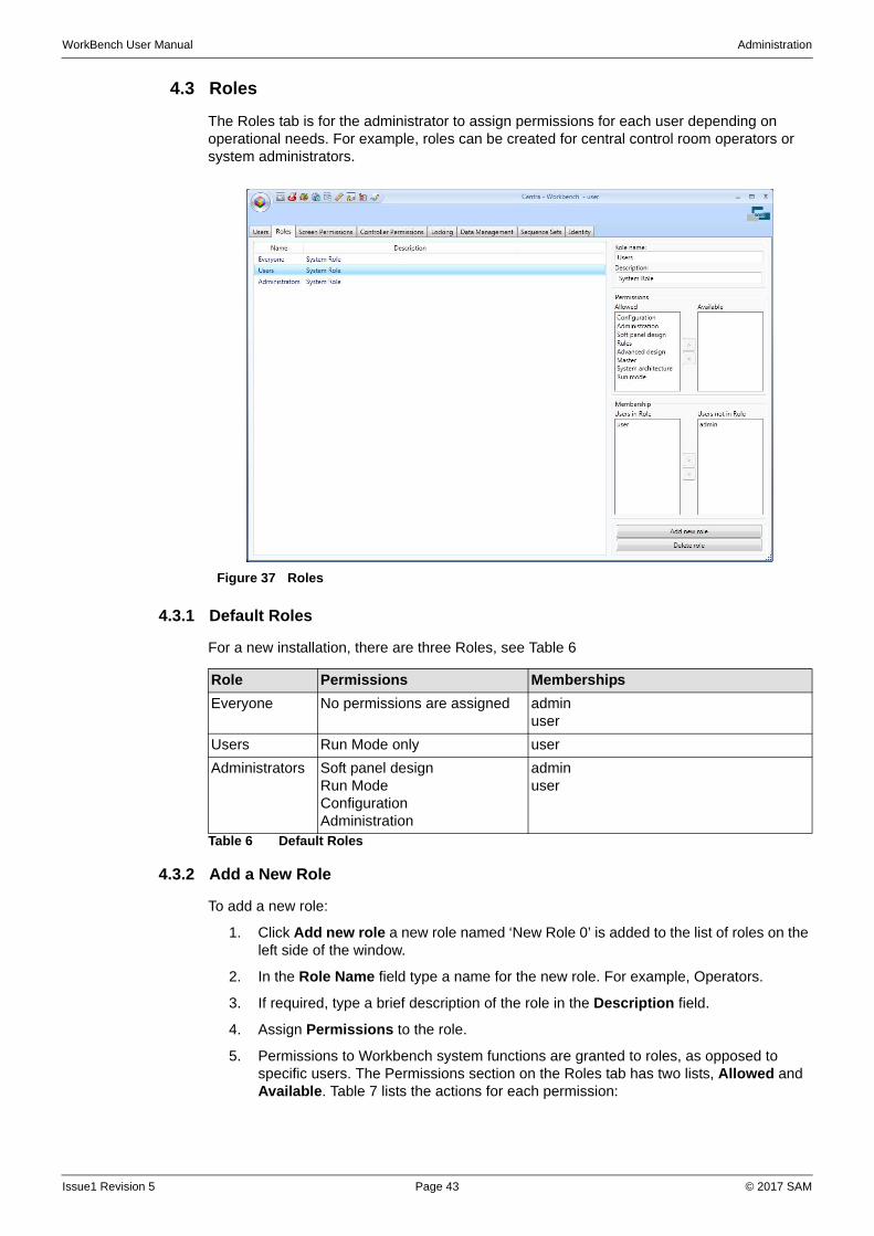
4.3 Roles
The Roles tab is for the administrator to assign permissions for each user depending on operational needs. For example, roles can be created for central control room operators or system administrators.
4.3.1 Default Roles
For a new installation, there are three Roles, see Table 6
4.3.2 Add a New Role
To add a new role:
1. Click Add new role a new role named ‘New Role 0’ is added to the list of roles on the left side of the window.
2. In the Role Name field type a name for the new role. For example, Operators.
3. If required, type a brief description of the role in the Description field.
4. Assign Permissions to the role.
5. Permissions to Workbench system functions are granted to roles, as opposed to specific users. The Permissions section on the Roles tab has two lists, Allowed and Available. Table 7 lists the actions for each permission:
Figure 37 Roles
Role Permissions Memberships
Everyone No permissions are assigned adminuser
Users Run Mode only user
Administrators Soft panel designRun ModeConfigurationAdministration
adminuser
Table 6 Default Roles
Issue1 Revision 5 Page 43 © 2017 SAM
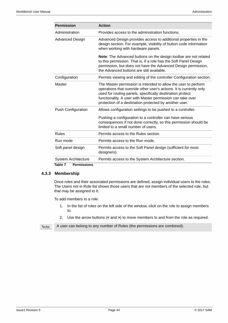
WorkBench User Manual Administration
4.3.3 Membership
Once roles and their associated permissions are defined, assign individual users to the roles. The Users not in Role list shows those users that are not members of the selected role, but that may be assigned to it.
To add members to a role:
1. In the list of roles on the left side of the window, click on the role to assign members to.
2. Use the arrow buttons (< and >) to move members to and from the role as required.
Permission Action
Administration Provides access to the administration functions.
Advanced Design Advanced Design provides access to additional properties in the design section. For example, visibility of button code information when working with hardware panels.
Note: The Advanced buttons on the design toolbar are not related to this permission. That is, if a role has the Soft Panel Design permission, but does not have the Advanced Design permission, the Advanced buttons are still available.
Configuration Permits viewing and editing of the controller Configuration section.
Master The Master permission is intended to allow the user to perform operations that override other user's actions. It is currently only used for routing panels, specifically destination protect functionality. A user with Master permission can take over protection of a destination protected by another user.
Push Configuration Allows configuration settings to be pushed to a controller.
Pushing a configuration to a controller can have serious consequences if not done correctly, so this permission should be limited to a small number of users.
Rules Permits access to the Rules section.
Run mode Permits access to the Run mode.
Soft panel design Permits access to the Soft Panel design (sufficient for most designers).
System Architecture Permits access to the System Architecture section.
Table 7 Permissions
Note: A user can belong to any number of Roles (the permissions are combined).
Issue1 Revision 5 Page 44 © 2017 SAM
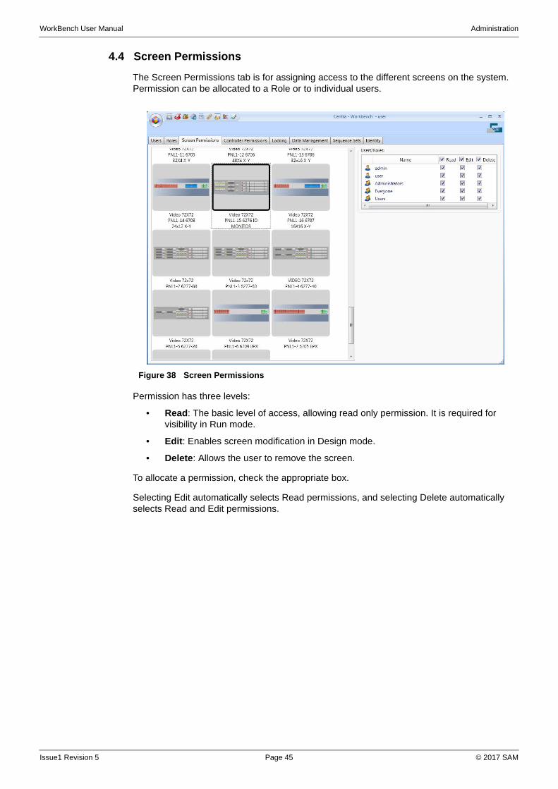
WorkBench User Manual Administration
4.4 Screen Permissions
The Screen Permissions tab is for assigning access to the different screens on the system. Permission can be allocated to a Role or to individual users.
Permission has three levels:
• Read: The basic level of access, allowing read only permission. It is required for visibility in Run mode.
• Edit: Enables screen modification in Design mode.
• Delete: Allows the user to remove the screen.
To allocate a permission, check the appropriate box.
Selecting Edit automatically selects Read permissions, and selecting Delete automatically selects Read and Edit permissions.
Figure 38 Screen Permissions
Issue1 Revision 5 Page 45 © 2017 SAM
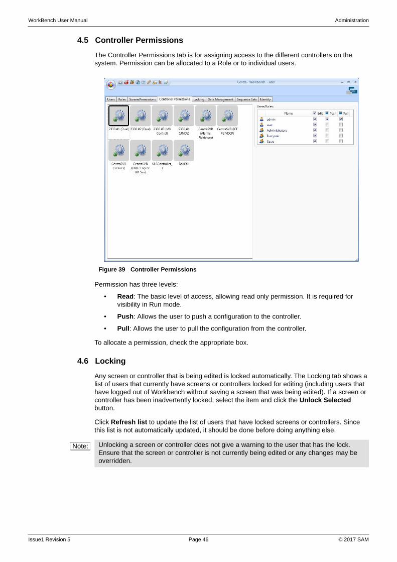
WorkBench User Manual Administration
4.5 Controller Permissions
The Controller Permissions tab is for assigning access to the different controllers on the system. Permission can be allocated to a Role or to individual users.
Permission has three levels:
• Read: The basic level of access, allowing read only permission. It is required for visibility in Run mode.
• Push: Allows the user to push a configuration to the controller.
• Pull: Allows the user to pull the configuration from the controller.
To allocate a permission, check the appropriate box.
4.6 Locking
Any screen or controller that is being edited is locked automatically. The Locking tab shows a list of users that currently have screens or controllers locked for editing (including users that have logged out of Workbench without saving a screen that was being edited). If a screen or controller has been inadvertently locked, select the item and click the Unlock Selected button.
Click Refresh list to update the list of users that have locked screens or controllers. Since this list is not automatically updated, it should be done before doing anything else.
Figure 39 Controller Permissions
Note: Unlocking a screen or controller does not give a warning to the user that has the lock. Ensure that the screen or controller is not currently being edited or any changes may be overridden.
Issue1 Revision 5 Page 46 © 2017 SAM

WorkBench User Manual Administration
4.7 Data Management
The Data Management tab is used for backing up and restoring Workbench screens, and for repairing the database.
The tab also shows the path to the current database, and licensing details.
4.7.1 Screen Management
To backup screens:
1. Click Backup Screens.
2. Browse to the folder into which the backup files are to be saved and then click OK.
To restore screens:
1. Click Restore Screens.
2. A warning screen displays stating that all existing objects will be deleted. All changes that have been made since the backup file was created will be lost.
3. If this is acceptable, click OK. If not, click No.
4.7.2 Database Repair
These functions are used to ‘clean’ the database and purge unused items.
To remove unassigned widgets and behaviors with no association:
1. Click on the Remove Orphaned Objects button.
2. A warning screen displays.
3. If this is acceptable, click OK. If not, click No.
4. When complete, a summary screen displays indicating the number of changes made.
To fix widgets that have an invalid behavior, for example, add a passive behavior to widgets with a null behavior:
1. Click on the Fix Widget Behaviors button.
A window displays showing the screens that contain null behavior widgets.
2. Select the screens to be fixed, and click OK.
3. When complete, a summary screen displays indicating the number of changes made.
Note: It is possible to export individual screens from the Design screen, Individual Controllers from Configuration or the entire database using SQL Management Studio. For information about performing database backup and restoration from SQL Management Studio, refer to the SQL Management Studio online help.
Important: The following functions change the database, and cannot be undone. Ensure the database has been backed up before using these functions.
Issue1 Revision 5 Page 47 © 2017 SAM
WorkBench User Manual Administration
4.8 Sequence Sets
Sequence Sets are required for soft panel configuration. Sequence Sets group the key entry sequences that are required to enter sources and destinations via keypads.
To add a sequence set:
• Click on the Add button.
Key sequences are defined either on the fly using a dial-up keypad on a soft panel, or in the Key Sequences Editor in Design mode. See “Key Sequences” on page 128.
To remove a sequence set:
• Select a sequence set from the list, and click the Remove button.
4.9 Identity
The Identity tab lists the Machines, External Clients and Internal Clients that are present on the network, and are linked to Workbench. It identifies which soft panel client has protected a route.
Machines PCs running Workbench router configuration software
External Clients PCs running Workbench soft panels
Internal Clients Hardware control panels connected directly to the router controller
Issue1 Revision 5 Page 48 © 2017 SAM
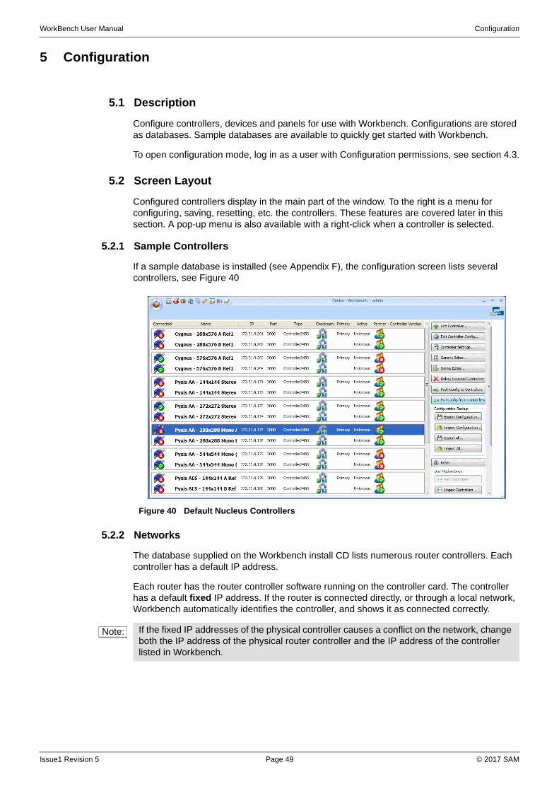
WorkBench User Manual Configuration
5 Configuration
5.1 Description
Configure controllers, devices and panels for use with Workbench. Configurations are stored as databases. Sample databases are available to quickly get started with Workbench.
To open configuration mode, log in as a user with Configuration permissions, see section 4.3.
5.2 Screen Layout
Configured controllers display in the main part of the window. To the right is a menu for configuring, saving, resetting, etc. the controllers. These features are covered later in this section. A pop-up menu is also available with a right-click when a controller is selected.
5.2.1 Sample Controllers
If a sample database is installed (see Appendix F), the configuration screen lists several controllers, see Figure 40
5.2.2 Networks
The database supplied on the Workbench install CD lists numerous router controllers. Each controller has a default IP address.
Each router has the router controller software running on the controller card. The controller has a default fixed IP address. If the router is connected directly, or through a local network, Workbench automatically identifies the controller, and shows it as connected correctly.
Figure 40 Default Nucleus Controllers
Note: If the fixed IP addresses of the physical controller causes a conflict on the network, change both the IP address of the physical router controller and the IP address of the controller listed in Workbench.
Issue1 Revision 5 Page 49 © 2017 SAM
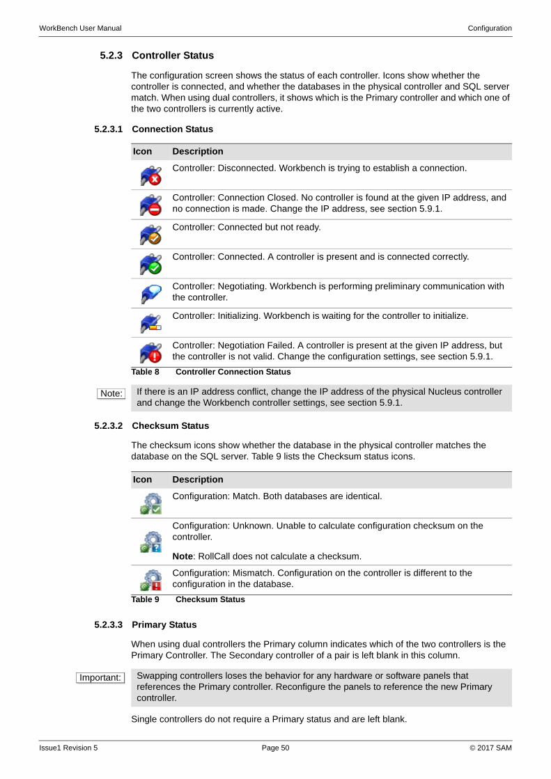
WorkBench User Manual Configuration
5.2.3 Controller Status
The configuration screen shows the status of each controller. Icons show whether the controller is connected, and whether the databases in the physical controller and SQL server match. When using dual controllers, it shows which is the Primary controller and which one of the two controllers is currently active.
5.2.3.1 Connection Status
5.2.3.2 Checksum Status
The checksum icons show whether the database in the physical controller matches the database on the SQL server. Table 9 lists the Checksum status icons.
5.2.3.3 Primary Status
When using dual controllers the Primary column indicates which of the two controllers is the Primary Controller. The Secondary controller of a pair is left blank in this column.
Single controllers do not require a Primary status and are left blank.
Icon Description
Controller: Disconnected. Workbench is trying to establish a connection.
Controller: Connection Closed. No controller is found at the given IP address, and no connection is made. Change the IP address, see section 5.9.1.
Controller: Connected but not ready.
Controller: Connected. A controller is present and is connected correctly.
Controller: Negotiating. Workbench is performing preliminary communication with the controller.
Controller: Initializing. Workbench is waiting for the controller to initialize.
Controller: Negotiation Failed. A controller is present at the given IP address, but the controller is not valid. Change the configuration settings, see section 5.9.1.
Table 8 Controller Connection Status
Note: If there is an IP address conflict, change the IP address of the physical Nucleus controller and change the Workbench controller settings, see section 5.9.1.
Icon Description
Configuration: Match. Both databases are identical.
Configuration: Unknown. Unable to calculate configuration checksum on the controller.
Note: RollCall does not calculate a checksum.
Configuration: Mismatch. Configuration on the controller is different to the configuration in the database.
Table 9 Checksum Status
Important: Swapping controllers loses the behavior for any hardware or software panels that references the Primary controller. Reconfigure the panels to reference the new Primary controller.
Issue1 Revision 5 Page 50 © 2017 SAM
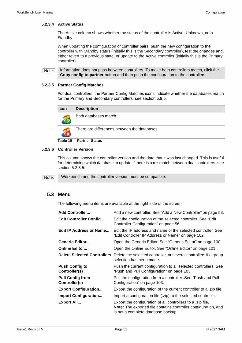
WorkBench User Manual Configuration
5.2.3.4 Active Status
The Active column shows whether the status of the controller is Active, Unknown, or in Standby.
When updating the configuration of controller pairs, push the new configuration to the controller with Standby status (initially this is the Secondary controller), test the changes and, either revert to a previous state, or update to the Active controller (initially this is the Primary controller).
5.2.3.5 Partner Config Matches
For dual controllers, the Partner Config Matches icons indicate whether the databases match for the Primary and Secondary controllers, see section 5.9.5.
5.2.3.6 Controller Version
This column shows the controller version and the date that it was last changed. This is useful for determining which database to update if there is a mismatch between dual controllers, see section 5.2.3.5.
5.3 Menu
The following menu items are available at the right side of the screen:
Note: Information does not pass between controllers. To make both controllers match, click the Copy config to partner button and then push the configuration to the controllers.
Icon Description
Both databases match.
There are differences between the databases.
Table 10 Partner Status
Note: Workbench and the controller version must be compatible.
Add Controller... Add a new controller. See “Add a New Controller” on page 53.
Edit Controller Config... Edit the configuration of the selected controller. See “Edit Controller Configuration” on page 56.
Edit IP Address or Name... Edit the IP address and name of the selected controller. See “Edit Controller IP Address or Name” on page 102.
Generic Editor... Open the Generic Editor. See “Generic Editor” on page 100.
Online Editor... Open the Online Editor. See “Online Editor” on page 101.
Delete Selected Controllers Delete the selected controller, or several controllers if a group selection has been made.
Push Config to Controller(s)
Push the current configuration to all selected controllers. See “Push and Pull Configuration” on page 103.
Pull Config from Controller(s)
Pull the configuration from a controller. See “Push and Pull Configuration” on page 103.
Export Configuration... Export the configuration of the current controller to a .zip file.
Import Configuration... Import a configuration file (.zip) to the selected controller.
Export All... Export the configuration of all controllers to a .zip file.Note: The exported file contains controller configuration, and is not a complete database backup.
Issue1 Revision 5 Page 51 © 2017 SAM
WorkBench User Manual Configuration
With a controller selected, a right-click displays some of the above menu items in a pop-up menu, plus the following additional menu items:
Import All... Import a configuration file (.zip) to all controllers.
Reset Resets the selected controller. See “Reset” on page 104.
Pair Controllers Pair two similar controllers to give a dual redundancy. See “Dual Redundancy” on page 104.
Unpair Controllers Unpair two paired controllers.
Swap Pair Set the Primary controller to be the Secondary controller, and the Secondary controller to be the Primary controller. See “Swap Controllers” on page 105.
Copy config to partner Copy the configuration of one controller to the other in the pair, ensuring the configuration matches. See “Copy Config to Partner” on page 105.
Refresh Refreshes the list of controllers, and enables/disables menu functions, as applicable.
Connections List the active controller connections. See “Connections” on page 106.
Oid Rewriter... Change OID references. See “OID Rewrite Helper” on page 106.
Snapshot Editor... Save the current crosspoint configuration to a snapshot file, or import a saved snapshot configuration file. See “Snapshot Editor” on page 107.
Delete RollCall Cache Clears the cache of RollCall menu set data. See “Delete RollCall Cache” on page 110.
Find Usages... Opens a new window listing the screen and rules that reference the selected controller.
Convert to 246x When replacing an existing Nucleus 2450 controller with a new Nucleus 246x controller, convert the 2450 configuration to that of a 246x without having to reconfigure the new controller. See “Convert a Nucleus 2450 Controller to a 246x Controller” on page 110.
Create Default Screen Opens the New Screen Wizard for panels. See “Screens” on page 115.
Issue1 Revision 5 Page 52 © 2017 SAM
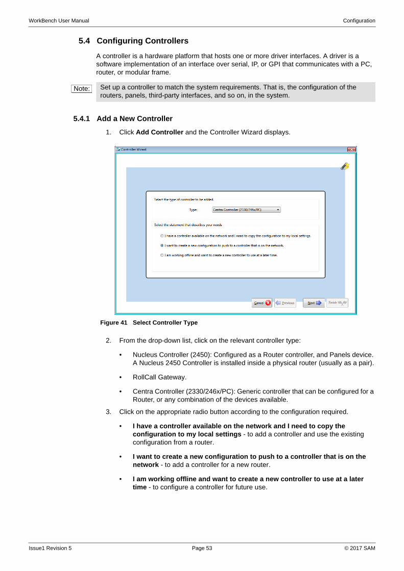
WorkBench User Manual Configuration
5.4 Configuring Controllers
A controller is a hardware platform that hosts one or more driver interfaces. A driver is a software implementation of an interface over serial, IP, or GPI that communicates with a PC, router, or modular frame.
5.4.1 Add a New Controller
1. Click Add Controller and the Controller Wizard displays.
2. From the drop-down list, click on the relevant controller type:
• Nucleus Controller (2450): Configured as a Router controller, and Panels device. A Nucleus 2450 Controller is installed inside a physical router (usually as a pair).
• RollCall Gateway.
• Centra Controller (2330/246x/PC): Generic controller that can be configured for a Router, or any combination of the devices available.
3. Click on the appropriate radio button according to the configuration required.
• I have a controller available on the network and I need to copy the configuration to my local settings - to add a controller and use the existing configuration from a router.
• I want to create a new configuration to push to a controller that is on the network - to add a controller for a new router.
• I am working offline and want to create a new controller to use at a later time - to configure a controller for future use.
Note: Set up a controller to match the system requirements. That is, the configuration of the routers, panels, third-party interfaces, and so on, in the system.
Figure 41 Select Controller Type
Issue1 Revision 5 Page 53 © 2017 SAM
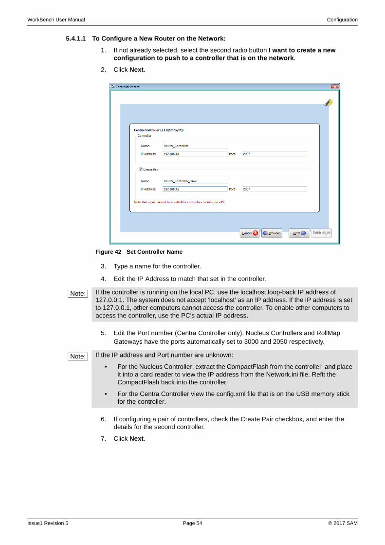
WorkBench User Manual Configuration
5.4.1.1 To Configure a New Router on the Network:
1. If not already selected, select the second radio button I want to create a new configuration to push to a controller that is on the network.
2. Click Next.
3. Type a name for the controller.
4. Edit the IP Address to match that set in the controller.
5. Edit the Port number (Centra Controller only). Nucleus Controllers and RollMap Gateways have the ports automatically set to 3000 and 2050 respectively.
6. If configuring a pair of controllers, check the Create Pair checkbox, and enter the details for the second controller.
7. Click Next.
Figure 42 Set Controller Name
Note: If the controller is running on the local PC, use the localhost loop-back IP address of 127.0.0.1. The system does not accept ‘localhost’ as an IP address. If the IP address is set to 127.0.0.1, other computers cannot access the controller. To enable other computers to access the controller, use the PC’s actual IP address.
Note: If the IP address and Port number are unknown:
• For the Nucleus Controller, extract the CompactFlash from the controller and place it into a card reader to view the IP address from the Network.ini file. Refit the CompactFlash back into the controller.
• For the Centra Controller view the config.xml file that is on the USB memory stick for the controller.
Issue1 Revision 5 Page 54 © 2017 SAM
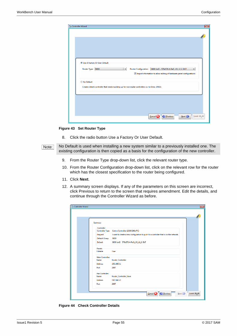
WorkBench User Manual Configuration
8. Click the radio button Use a Factory Or User Default.
9. From the Router Type drop-down list, click the relevant router type.
10. From the Router Configuration drop-down list, click on the relevant row for the router which has the closest specification to the router being configured.
11. Click Next.
12. A summary screen displays. If any of the parameters on this screen are incorrect, click Previous to return to the screen that requires amendment. Edit the details, and continue through the Controller Wizard as before.
Figure 43 Set Router Type
Note: No Default is used when installing a new system similar to a previously installed one. The existing configuration is then copied as a basis for the configuration of the new controller.
Figure 44 Check Controller Details
Issue1 Revision 5 Page 55 © 2017 SAM
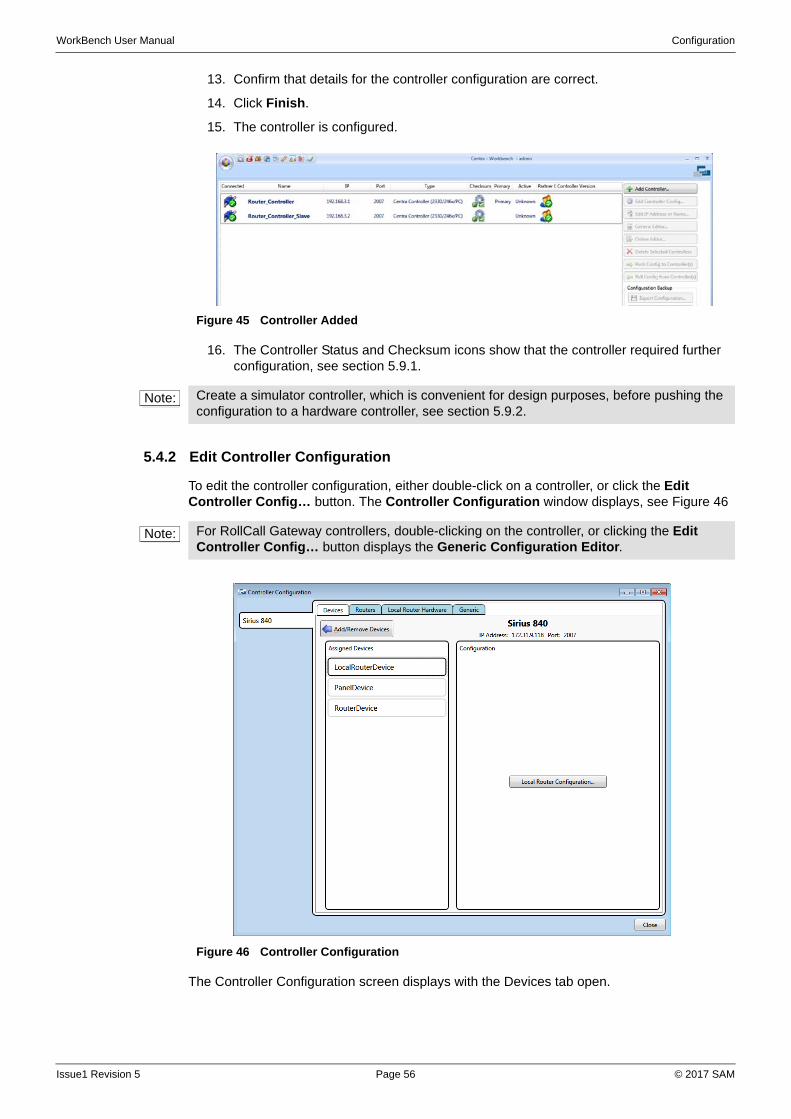
WorkBench User Manual Configuration
13. Confirm that details for the controller configuration are correct.
14. Click Finish.
15. The controller is configured.
16. The Controller Status and Checksum icons show that the controller required further configuration, see section 5.9.1.
5.4.2 Edit Controller Configuration
To edit the controller configuration, either double-click on a controller, or click the Edit Controller Config… button. The Controller Configuration window displays, see Figure 46
The Controller Configuration screen displays with the Devices tab open.
Figure 45 Controller Added
Note: Create a simulator controller, which is convenient for design purposes, before pushing the configuration to a hardware controller, see section 5.9.2.
Note: For RollCall Gateway controllers, double-clicking on the controller, or clicking the Edit Controller Config… button displays the Generic Configuration Editor.
Figure 46 Controller Configuration
Issue1 Revision 5 Page 56 © 2017 SAM
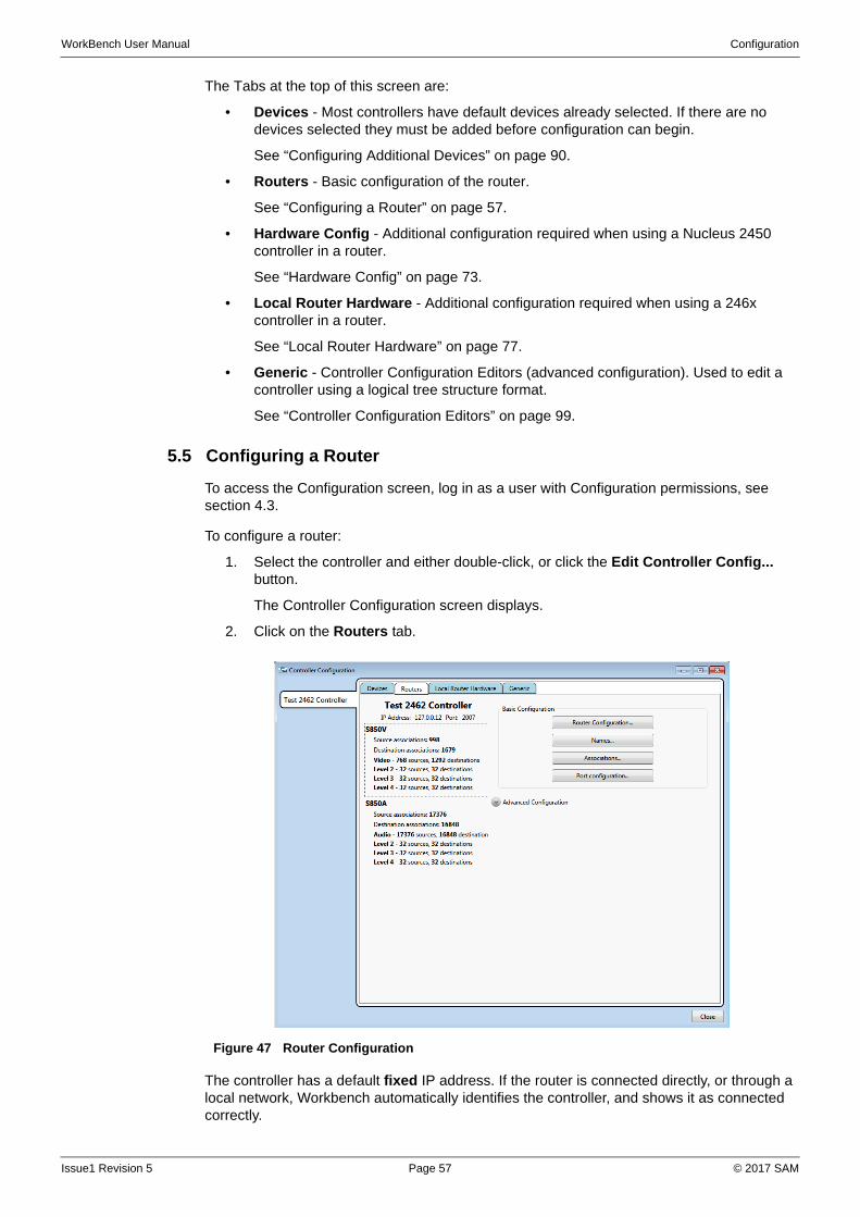
WorkBench User Manual Configuration
The Tabs at the top of this screen are:
• Devices - Most controllers have default devices already selected. If there are no devices selected they must be added before configuration can begin.
See “Configuring Additional Devices” on page 90.
• Routers - Basic configuration of the router.
See “Configuring a Router” on page 57.
• Hardware Config - Additional configuration required when using a Nucleus 2450 controller in a router.
See “Hardware Config” on page 73.
• Local Router Hardware - Additional configuration required when using a 246x controller in a router.
See “Local Router Hardware” on page 77.
• Generic - Controller Configuration Editors (advanced configuration). Used to edit a controller using a logical tree structure format.
See “Controller Configuration Editors” on page 99.
5.5 Configuring a Router
To access the Configuration screen, log in as a user with Configuration permissions, see section 4.3.
To configure a router:
1. Select the controller and either double-click, or click the Edit Controller Config... button.
The Controller Configuration screen displays.
2. Click on the Routers tab.
The controller has a default fixed IP address. If the router is connected directly, or through a local network, Workbench automatically identifies the controller, and shows it as connected correctly.
Figure 47 Router Configuration
Issue1 Revision 5 Page 57 © 2017 SAM
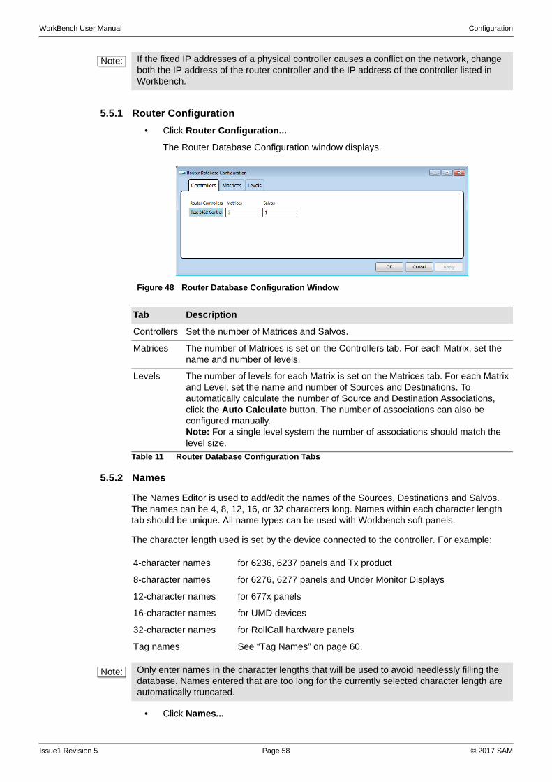
WorkBench User Manual Configuration
5.5.1 Router Configuration
• Click Router Configuration...
The Router Database Configuration window displays.
5.5.2 Names
The Names Editor is used to add/edit the names of the Sources, Destinations and Salvos. The names can be 4, 8, 12, 16, or 32 characters long. Names within each character length tab should be unique. All name types can be used with Workbench soft panels.
The character length used is set by the device connected to the controller. For example:
• Click Names...
Note: If the fixed IP addresses of a physical controller causes a conflict on the network, change both the IP address of the router controller and the IP address of the controller listed in Workbench.
Figure 48 Router Database Configuration Window
Tab Description
Controllers Set the number of Matrices and Salvos.
Matrices The number of Matrices is set on the Controllers tab. For each Matrix, set the name and number of levels.
Levels The number of levels for each Matrix is set on the Matrices tab. For each Matrix and Level, set the name and number of Sources and Destinations. To automatically calculate the number of Source and Destination Associations, click the Auto Calculate button. The number of associations can also be configured manually.Note: For a single level system the number of associations should match the level size.
Table 11 Router Database Configuration Tabs
4-character names for 6236, 6237 panels and Tx product
8-character names for 6276, 6277 panels and Under Monitor Displays
12-character names for 677x panels
16-character names for UMD devices
32-character names for RollCall hardware panels
Tag names See “Tag Names” on page 60.
Note: Only enter names in the character lengths that will be used to avoid needlessly filling the database. Names entered that are too long for the currently selected character length are automatically truncated.
Issue1 Revision 5 Page 58 © 2017 SAM
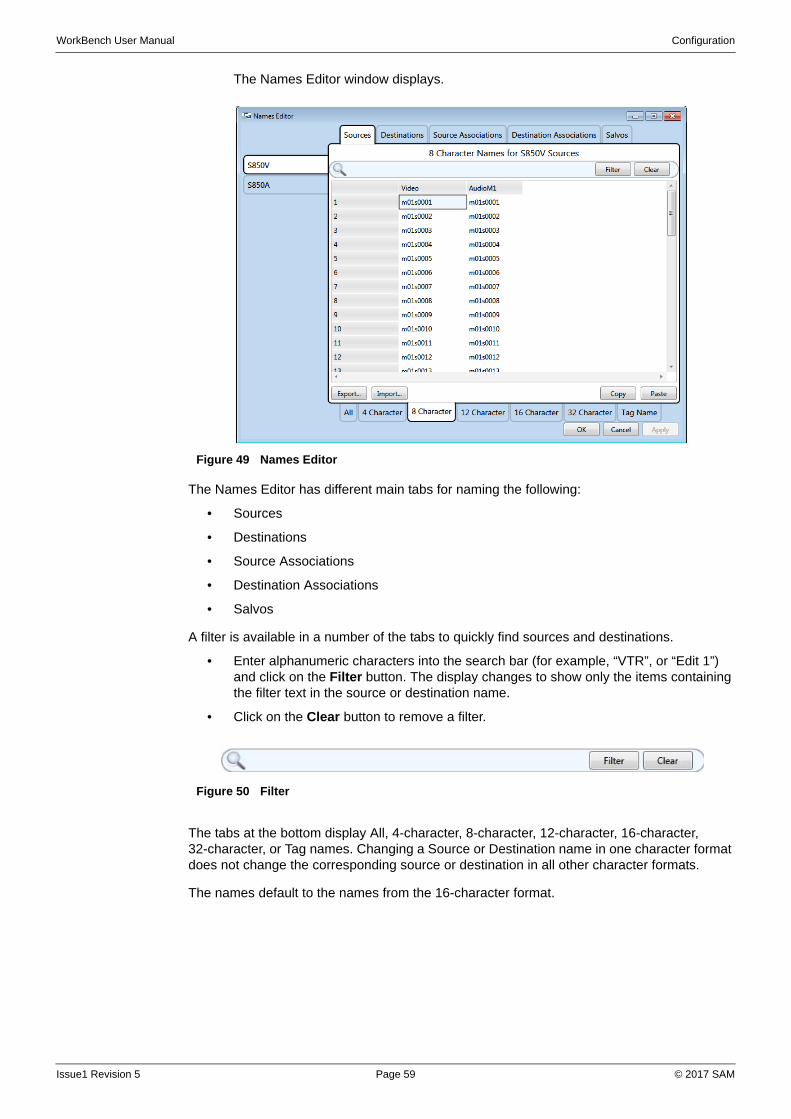
WorkBench User Manual Configuration
The Names Editor window displays.
The Names Editor has different main tabs for naming the following:
• Sources
• Destinations
• Source Associations
• Destination Associations
• Salvos
A filter is available in a number of the tabs to quickly find sources and destinations.
• Enter alphanumeric characters into the search bar (for example, “VTR”, or “Edit 1”) and click on the Filter button. The display changes to show only the items containing the filter text in the source or destination name.
• Click on the Clear button to remove a filter.
The tabs at the bottom display All, 4-character, 8-character, 12-character, 16-character, 32-character, or Tag names. Changing a Source or Destination name in one character format does not change the corresponding source or destination in all other character formats.
The names default to the names from the 16-character format.
Figure 49 Names Editor
Figure 50 Filter
Issue1 Revision 5 Page 59 © 2017 SAM
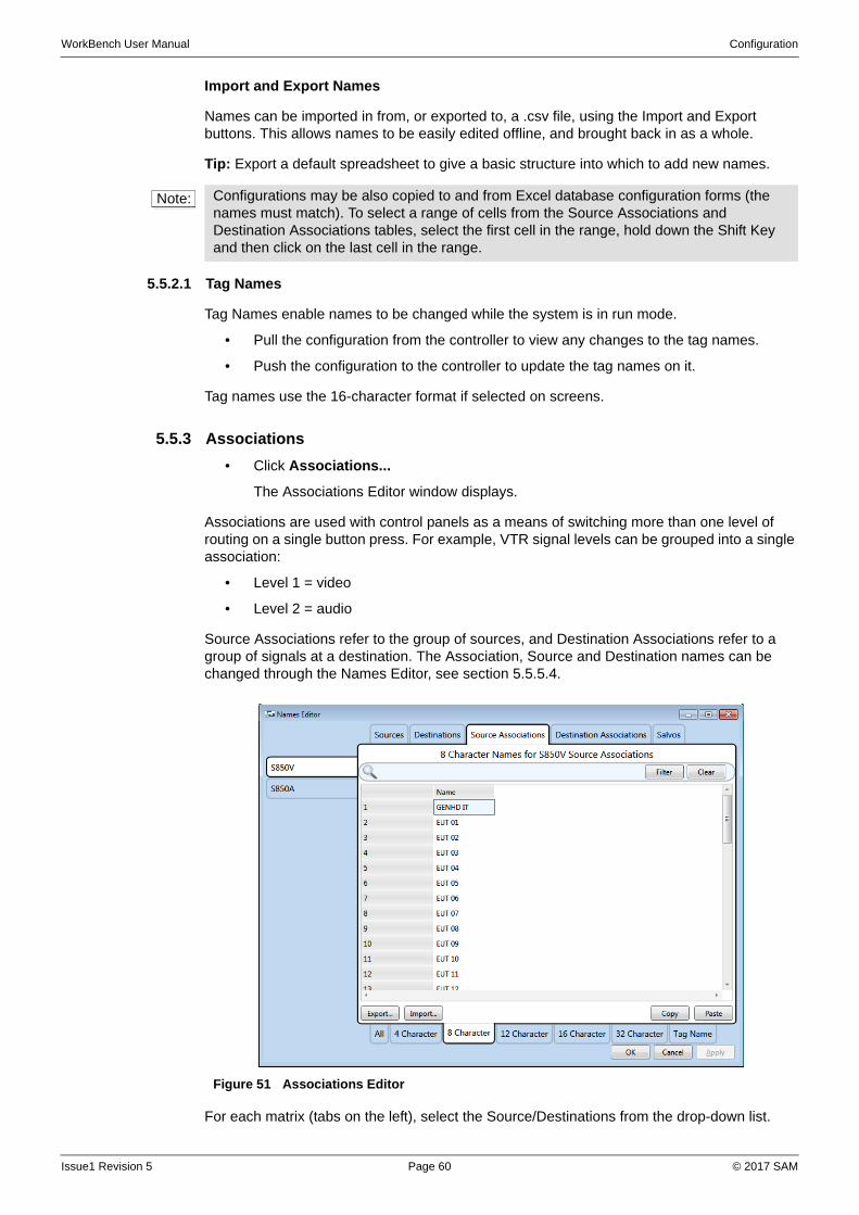
WorkBench User Manual Configuration
Import and Export Names
Names can be imported in from, or exported to, a .csv file, using the Import and Export buttons. This allows names to be easily edited offline, and brought back in as a whole.
Tip: Export a default spreadsheet to give a basic structure into which to add new names.
5.5.2.1 Tag Names
Tag Names enable names to be changed while the system is in run mode.
• Pull the configuration from the controller to view any changes to the tag names.
• Push the configuration to the controller to update the tag names on it.
Tag names use the 16-character format if selected on screens.
5.5.3 Associations
• Click Associations...
The Associations Editor window displays.
Associations are used with control panels as a means of switching more than one level of routing on a single button press. For example, VTR signal levels can be grouped into a single association:
• Level 1 = video
• Level 2 = audio
Source Associations refer to the group of sources, and Destination Associations refer to a group of signals at a destination. The Association, Source and Destination names can be changed through the Names Editor, see section 5.5.5.4.
For each matrix (tabs on the left), select the Source/Destinations from the drop-down list.
Note: Configurations may be also copied to and from Excel database configuration forms (the names must match). To select a range of cells from the Source Associations and Destination Associations tables, select the first cell in the range, hold down the Shift Key and then click on the last cell in the range.
Figure 51 Associations Editor
Issue1 Revision 5 Page 60 © 2017 SAM
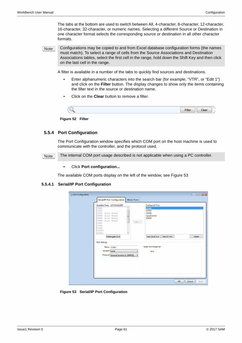
WorkBench User Manual Configuration
The tabs at the bottom are used to switch between All, 4-character, 8-character, 12-character, 16-character, 32-character, or numeric names. Selecting a different Source or Destination in one character format selects the corresponding source or destination in all other character formats.
A filter is available in a number of the tabs to quickly find sources and destinations.
• Enter alphanumeric characters into the search bar (for example, “VTR”, or “Edit 1”) and click on the Filter button. The display changes to show only the items containing the filter text in the source or destination name.
• Click on the Clear button to remove a filter.
5.5.4 Port Configuration
The Port Configuration window specifies which COM port on the host machine is used to communicate with the controller, and the protocol used.
• Click Port configuration...
The available COM ports display on the left of the window, see Figure 53
5.5.4.1 Serial/IP Port Configuration
Note: Configurations may be copied to and from Excel database configuration forms (the names must match). To select a range of cells from the Source Associations and Destination Associations tables, select the first cell in the range, hold down the Shift Key and then click on the last cell in the range.
Figure 52 Filter
Note: The internal COM port usage described is not applicable when using a PC controller.
Figure 53 Serial/IP Port Configuration
Issue1 Revision 5 Page 61 © 2017 SAM
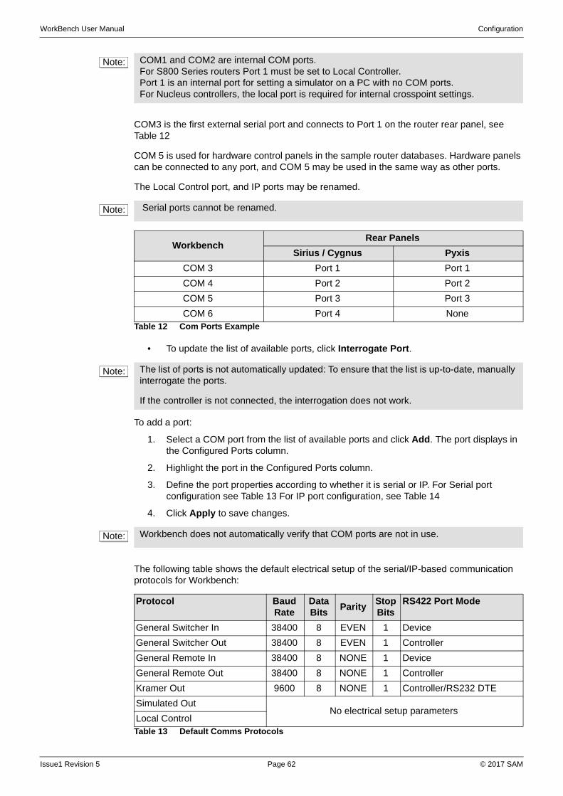
WorkBench User Manual Configuration
COM3 is the first external serial port and connects to Port 1 on the router rear panel, see Table 12
COM 5 is used for hardware control panels in the sample router databases. Hardware panels can be connected to any port, and COM 5 may be used in the same way as other ports.
The Local Control port, and IP ports may be renamed.
• To update the list of available ports, click Interrogate Port.
To add a port:
1. Select a COM port from the list of available ports and click Add. The port displays in the Configured Ports column.
2. Highlight the port in the Configured Ports column.
3. Define the port properties according to whether it is serial or IP. For Serial port configuration see Table 13 For IP port configuration, see Table 14
4. Click Apply to save changes.
The following table shows the default electrical setup of the serial/IP-based communication protocols for Workbench:
Note: COM1 and COM2 are internal COM ports.For S800 Series routers Port 1 must be set to Local Controller.Port 1 is an internal port for setting a simulator on a PC with no COM ports.For Nucleus controllers, the local port is required for internal crosspoint settings.
Note: Serial ports cannot be renamed.
WorkbenchRear Panels
Sirius / Cygnus Pyxis
COM 3 Port 1 Port 1
COM 4 Port 2 Port 2
COM 5 Port 3 Port 3
COM 6 Port 4 NoneTable 12 Com Ports Example
Note: The list of ports is not automatically updated: To ensure that the list is up-to-date, manually interrogate the ports.
If the controller is not connected, the interrogation does not work.
Note: Workbench does not automatically verify that COM ports are not in use.
Protocol Baud Rate
Data Bits
ParityStop Bits
RS422 Port Mode
General Switcher In 38400 8 EVEN 1 Device
General Switcher Out 38400 8 EVEN 1 Controller
General Remote In 38400 8 NONE 1 Device
General Remote Out 38400 8 NONE 1 Controller
Kramer Out 9600 8 NONE 1 Controller/RS232 DTE
Simulated OutNo electrical setup parameters
Local ControlTable 13 Default Comms Protocols
Issue1 Revision 5 Page 62 © 2017 SAM
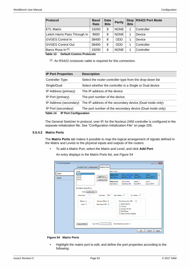
WorkBench User Manual Configuration
The General Switcher In protocol, over IP, for the Nucleus 2450 controller is configured in the separate initialization file. See “Configuration Initialization File” on page 205.
5.5.4.2 Matrix Ports
The Matrix Ports tab makes it possible to map the logical arrangement of signals defined in the Matrix and Levels to the physical inputs and outputs of the routers.
• To add a Matrix Port, select the Matrix and Level, and click Add Port.
An entry displays in the Matrix Ports list, see Figure 54
• Highlight the matrix port to edit, and define the port properties according to the following:
ETL Matrix 19200 8 NONE 1 Controller
Leitch Harris Pass Through In 9600 8 NONE 1 Device
GVGES Control In 38400 8 ODD 1 Device
GVGES Control Out 38400 8 ODD 1 Controller
Barco Rosa In [1] 19200 8 NONE 1 Controller
[1] An RS422 crossover cable is required for this connection.
IP Port Properties Description
Controller Type Select the router controller type from the drop-down list
Single/Dual Select whether the controller is a Single or Dual device
IP Address (primary) The IP address of the device
IP Port (primary) The port number of the device
IP Address (secondary) The IP address of the secondary device (Dual mode only)
IP Port (secondary) The port number of the secondary device (Dual mode only)
Table 14 IP Port Configuration
Protocol Baud Rate
Data Bits
ParityStop Bits
RS422 Port Mode
Table 13 Default Comms Protocols
Figure 54 Matrix Ports
Issue1 Revision 5 Page 63 © 2017 SAM
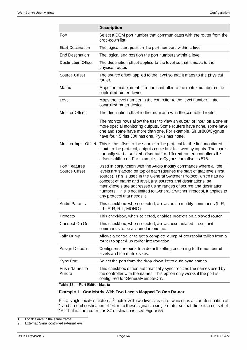
WorkBench User Manual Configuration
Example 1 - One Matrix With Two Levels Mapped To One Router
For a single local1 or external2 matrix with two levels, each of which has a start destination of 1 and an end destination of 16, map these signals a single router so that there is an offset of 16. That is, the router has 32 destinations, see Figure 55
Description
Port Select a COM port number that communicates with the router from the drop-down list.
Start Destination The logical start position the port numbers within a level.
End Destination The logical end position the port numbers within a level.
Destination Offset The destination offset applied to the level so that it maps to the physical router.
Source Offset The source offset applied to the level so that it maps to the physical router.
Matrix Maps the matrix number in the controller to the matrix number in the controlled router device.
Level Maps the level number in the controller to the level number in the controlled router device.
Monitor Offset The destination offset to the monitor row in the controlled router.
The monitor rows allow the user to view an output or input on a one or more special monitoring outputs. Some routers have none, some have one and some have more than one. For example, Sirius800/Cygnus have four, Sirius 600 has one, Pyxis has none.
Monitor Input Offset This is the offset to the source in the protocol for the first monitored input. In the protocol, outputs come first followed by inputs. The inputs normally start at a fixed offset but for different router controllers this offset is different. For example, for Cygnus the offset is 576.
Port Features Source Offset
Used in conjunction with the Audio modify commands where all the levels are stacked on top of each (defines the start of that levels first source). This is used in the General Switcher Protocol which has no concept of matrix and level, just sources and destinations, so matrix/levels are addressed using ranges of source and destination numbers. This is not limited to General Switcher Protocol, it applies to any protocol that needs it.
Audio Params This checkbox, when selected, allows audio modify commands (L-R, L-L, R-R, R-L, MONO).
Protects This checkbox, when selected, enables protects on a slaved router.
Connect On Go This checkbox, when selected, allows accumulated crosspoint commands to be actioned in one go.
Tally Dump Allows a controller to get a complete dump of crosspoint tallies from a router to speed up router interrogation.
Assign Defaults Configures the ports to a default setting according to the number of levels and the matrix sizes.
Sync Port Select the port from the drop-down list to auto-sync names.
Push Names to Aurora
This checkbox option automatically synchronizes the names used by the controller with the names. This option only works if the port is configured for GeneralRemoteOut.
Table 15 Port Editor Matrix
1. Local: Cards in the same frame2. External: Serial controlled external level
Issue1 Revision 5 Page 64 © 2017 SAM
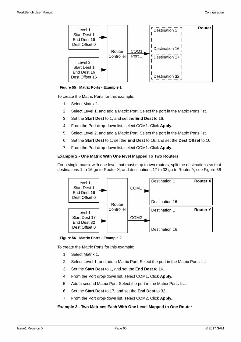
WorkBench User Manual Configuration
To create the Matrix Ports for this example:
1. Select Matrix 1.
2. Select Level 1, and add a Matrix Port. Select the port in the Matrix Ports list.
3. Set the Start Dest to 1, and set the End Dest to 16.
4. From the Port drop-down list, select COM1. Click Apply.
5. Select Level 2, and add a Matrix Port. Select the port in the Matrix Ports list.
6. Set the Start Dest to 1, set the End Dest to 16, and set the Dest Offset to 16.
7. From the Port drop-down list, select COM1. Click Apply.
Example 2 - One Matrix With One level Mapped To Two Routers
For a single matrix with one level that must map to two routers, split the destinations so that destinations 1 to 16 go to Router X, and destinations 17 to 32 go to Router Y, see Figure 56
To create the Matrix Ports for this example:
1. Select Matrix 1.
2. Select Level 1, and add a Matrix Port. Select the port in the Matrix Ports list.
3. Set the Start Dest to 1, and set the End Dest to 16.
4. From the Port drop-down list, select COM1. Click Apply.
5. Add a second Matrix Port. Select the port in the Matrix Ports list.
6. Set the Start Dest to 17, and set the End Dest to 32.
7. From the Port drop-down list, select COM2. Click Apply.
Example 3 - Two Matrices Each With One Level Mapped to One Router
Figure 55 Matrix Ports - Example 1
Figure 56 Matrix Ports - Example 2
Level 1Start Dest 1End Dest 16Dest Offset 0
Level 2Start Dest 1End Dest 16
Dest Offset 16
Router Controller
Router
COM1 Port 1
Destination 1
Destination 16
Destination 17
Destination 32
Level 1Start Dest 1End Dest 16Dest Offset 0
Level 1Start Dest 17End Dest 32Dest Offset 0
Router Controller
Router X
COM1
Destination 1
Destination 16
Destination 1
Destination 16
COM2
Router Y
Issue1 Revision 5 Page 65 © 2017 SAM
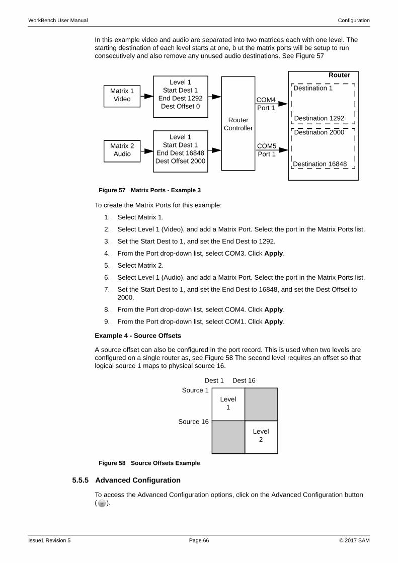
WorkBench User Manual Configuration
In this example video and audio are separated into two matrices each with one level. The starting destination of each level starts at one, b ut the matrix ports will be setup to run consecutively and also remove any unused audio destinations. See Figure 57
To create the Matrix Ports for this example:
1. Select Matrix 1.
2. Select Level 1 (Video), and add a Matrix Port. Select the port in the Matrix Ports list.
3. Set the Start Dest to 1, and set the End Dest to 1292.
4. From the Port drop-down list, select COM3. Click Apply.
5. Select Matrix 2.
6. Select Level 1 (Audio), and add a Matrix Port. Select the port in the Matrix Ports list.
7. Set the Start Dest to 1, and set the End Dest to 16848, and set the Dest Offset to 2000.
8. From the Port drop-down list, select COM4. Click Apply.
9. From the Port drop-down list, select COM1. Click Apply.
Example 4 - Source Offsets
A source offset can also be configured in the port record. This is used when two levels are configured on a single router as, see Figure 58 The second level requires an offset so that logical source 1 maps to physical source 16.
5.5.5 Advanced Configuration
To access the Advanced Configuration options, click on the Advanced Configuration button ( ).
Figure 57 Matrix Ports - Example 3
Figure 58 Source Offsets Example
Level 1Start Dest 1
End Dest 16848Dest Offset 2000
Router Controller
Router
COM4 Port 1
Destination 1
Destination 1292
Destination 2000
Destination 16848
Matrix 1Video
Matrix 2Audio
Level 1Start Dest 1
End Dest 1292Dest Offset 0
COM5 Port 1
Dest 1 Dest 16
Source 1
Source 16
Level1
Level2
Issue1 Revision 5 Page 66 © 2017 SAM
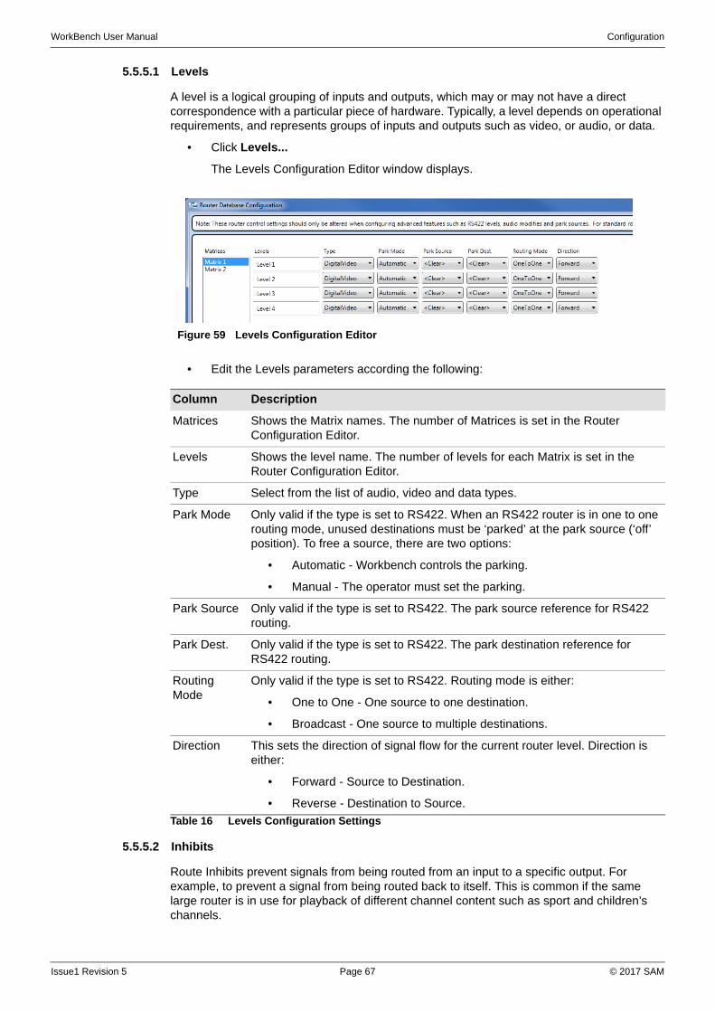
WorkBench User Manual Configuration
5.5.5.1 Levels
A level is a logical grouping of inputs and outputs, which may or may not have a direct correspondence with a particular piece of hardware. Typically, a level depends on operational requirements, and represents groups of inputs and outputs such as video, or audio, or data.
• Click Levels...
The Levels Configuration Editor window displays.
• Edit the Levels parameters according the following:
5.5.5.2 Inhibits
Route Inhibits prevent signals from being routed from an input to a specific output. For example, to prevent a signal from being routed back to itself. This is common if the same large router is in use for playback of different channel content such as sport and children’s channels.
Figure 59 Levels Configuration Editor
Column Description
Matrices Shows the Matrix names. The number of Matrices is set in the Router Configuration Editor.
Levels Shows the level name. The number of levels for each Matrix is set in the Router Configuration Editor.
Type Select from the list of audio, video and data types.
Park Mode Only valid if the type is set to RS422. When an RS422 router is in one to one routing mode, unused destinations must be ‘parked’ at the park source (‘off’ position). To free a source, there are two options:
• Automatic - Workbench controls the parking.
• Manual - The operator must set the parking.
Park Source Only valid if the type is set to RS422. The park source reference for RS422 routing.
Park Dest. Only valid if the type is set to RS422. The park destination reference for RS422 routing.
Routing Mode
Only valid if the type is set to RS422. Routing mode is either:
• One to One - One source to one destination.
• Broadcast - One source to multiple destinations.
Direction This sets the direction of signal flow for the current router level. Direction is either:
• Forward - Source to Destination.
• Reverse - Destination to Source.
Table 16 Levels Configuration Settings
Issue1 Revision 5 Page 67 © 2017 SAM
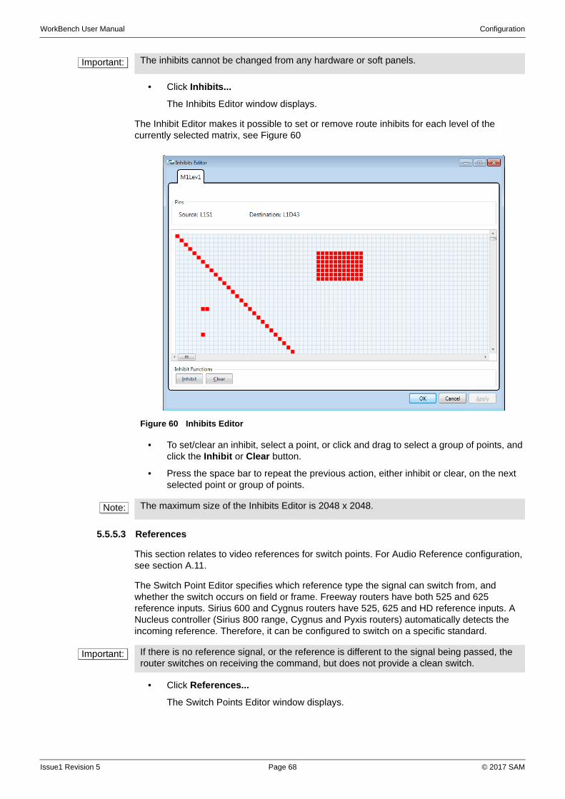
WorkBench User Manual Configuration
• Click Inhibits...
The Inhibits Editor window displays.
The Inhibit Editor makes it possible to set or remove route inhibits for each level of the currently selected matrix, see Figure 60
• To set/clear an inhibit, select a point, or click and drag to select a group of points, and click the Inhibit or Clear button.
• Press the space bar to repeat the previous action, either inhibit or clear, on the next selected point or group of points.
5.5.5.3 References
This section relates to video references for switch points. For Audio Reference configuration, see section A.11.
The Switch Point Editor specifies which reference type the signal can switch from, and whether the switch occurs on field or frame. Freeway routers have both 525 and 625 reference inputs. Sirius 600 and Cygnus routers have 525, 625 and HD reference inputs. A Nucleus controller (Sirius 800 range, Cygnus and Pyxis routers) automatically detects the incoming reference. Therefore, it can be configured to switch on a specific standard.
• Click References...
The Switch Points Editor window displays.
Important: The inhibits cannot be changed from any hardware or soft panels.
Figure 60 Inhibits Editor
Note: The maximum size of the Inhibits Editor is 2048 x 2048.
Important: If there is no reference signal, or the reference is different to the signal being passed, the router switches on receiving the command, but does not provide a clean switch.
Issue1 Revision 5 Page 68 © 2017 SAM
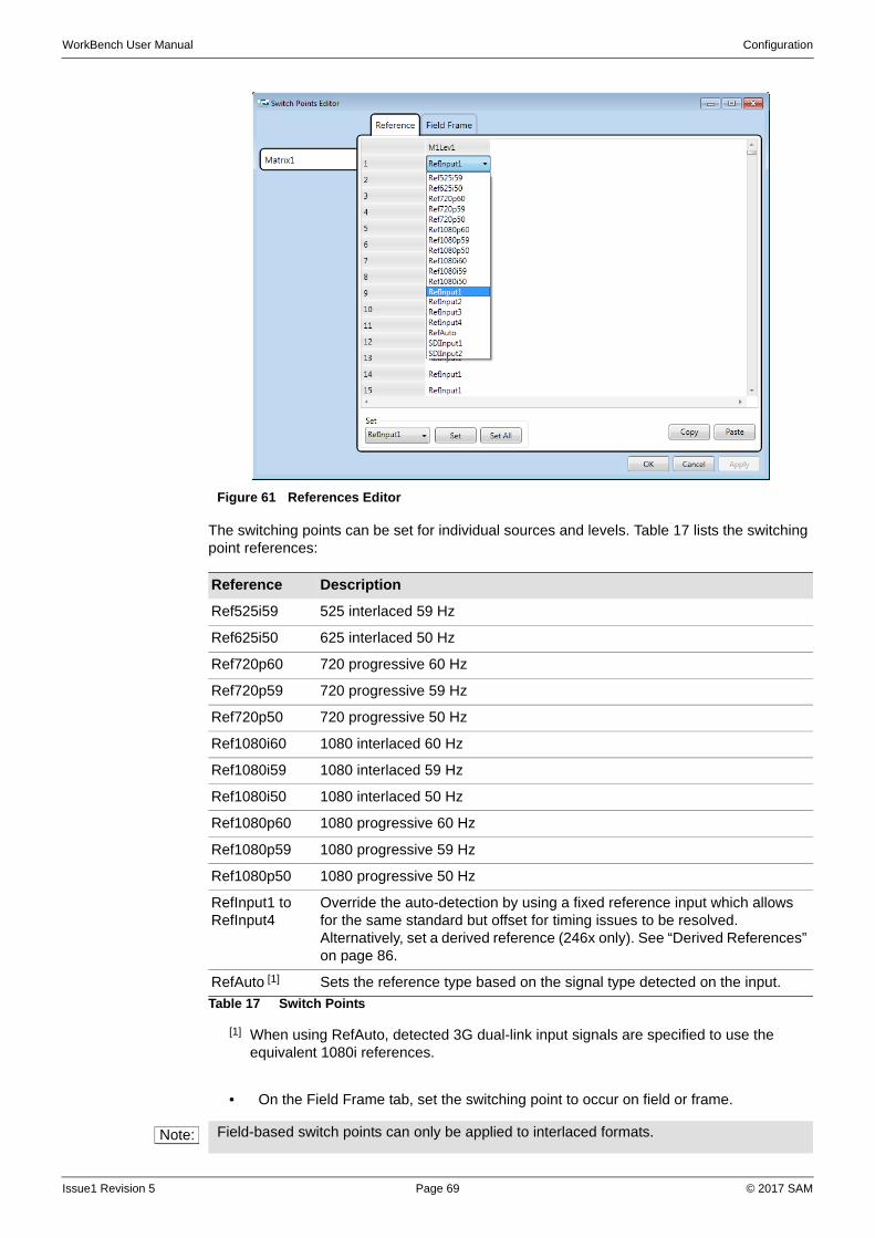
WorkBench User Manual Configuration
The switching points can be set for individual sources and levels. Table 17 lists the switching point references:
• On the Field Frame tab, set the switching point to occur on field or frame.
Figure 61 References Editor
Reference Description
Ref525i59 525 interlaced 59 Hz
Ref625i50 625 interlaced 50 Hz
Ref720p60 720 progressive 60 Hz
Ref720p59 720 progressive 59 Hz
Ref720p50 720 progressive 50 Hz
Ref1080i60 1080 interlaced 60 Hz
Ref1080i59 1080 interlaced 59 Hz
Ref1080i50 1080 interlaced 50 Hz
Ref1080p60 1080 progressive 60 Hz
Ref1080p59 1080 progressive 59 Hz
Ref1080p50 1080 progressive 50 Hz
RefInput1 to RefInput4
Override the auto-detection by using a fixed reference input which allows for the same standard but offset for timing issues to be resolved. Alternatively, set a derived reference (246x only). See “Derived References” on page 86.
RefAuto [1]
[1] When using RefAuto, detected 3G dual-link input signals are specified to use the equivalent 1080i references.
Sets the reference type based on the signal type detected on the input.
Table 17 Switch Points
Note: Field-based switch points can only be applied to interlaced formats.
Issue1 Revision 5 Page 69 © 2017 SAM
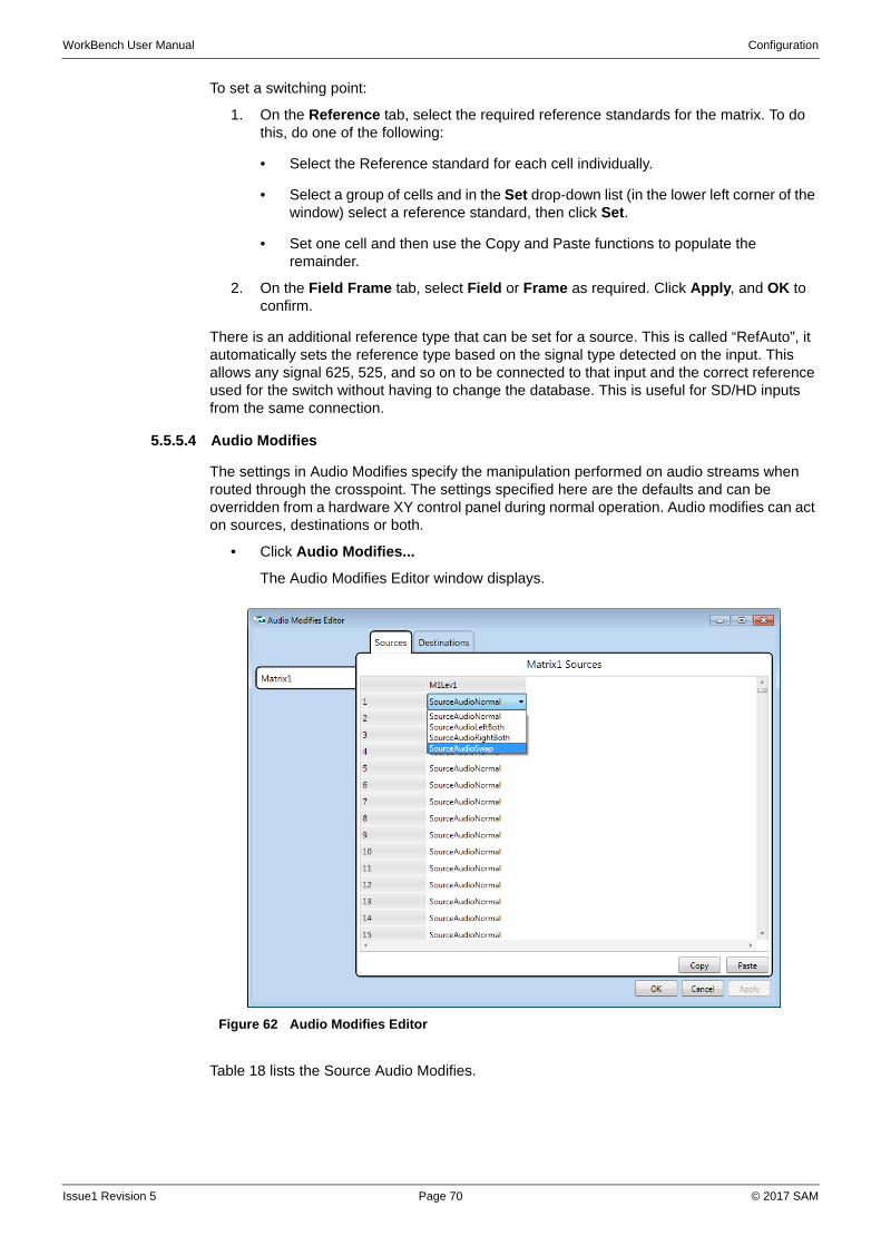
WorkBench User Manual Configuration
To set a switching point:
1. On the Reference tab, select the required reference standards for the matrix. To do this, do one of the following:
• Select the Reference standard for each cell individually.
• Select a group of cells and in the Set drop-down list (in the lower left corner of the window) select a reference standard, then click Set.
• Set one cell and then use the Copy and Paste functions to populate the remainder.
2. On the Field Frame tab, select Field or Frame as required. Click Apply, and OK to confirm.
There is an additional reference type that can be set for a source. This is called “RefAuto”, it automatically sets the reference type based on the signal type detected on the input. This allows any signal 625, 525, and so on to be connected to that input and the correct reference used for the switch without having to change the database. This is useful for SD/HD inputs from the same connection.
5.5.5.4 Audio Modifies
The settings in Audio Modifies specify the manipulation performed on audio streams when routed through the crosspoint. The settings specified here are the defaults and can be overridden from a hardware XY control panel during normal operation. Audio modifies can act on sources, destinations or both.
• Click Audio Modifies...
The Audio Modifies Editor window displays.
Table 18 lists the Source Audio Modifies.
Figure 62 Audio Modifies Editor
Issue1 Revision 5 Page 70 © 2017 SAM
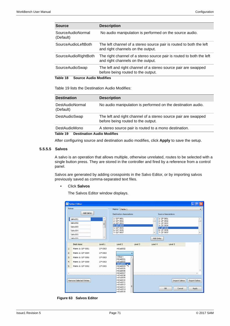
WorkBench User Manual Configuration
Table 19 lists the Destination Audio Modifies:
After configuring source and destination audio modifies, click Apply to save the setup.
5.5.5.5 Salvos
A salvo is an operation that allows multiple, otherwise unrelated, routes to be selected with a single button press. They are stored in the controller and fired by a reference from a control panel.
Salvos are generated by adding crosspoints in the Salvo Editor, or by importing salvos previously saved as comma-separated text files.
• Click Salvos
The Salvos Editor window displays.
Source Description
SourceAudioNormal (Default)
No audio manipulation is performed on the source audio.
SourceAudioLeftBoth The left channel of a stereo source pair is routed to both the left and right channels on the output.
SourceAudioRightBoth The right channel of a stereo source pair is routed to both the left and right channels on the output.
SourceAudioSwap The left and right channel of a stereo source pair are swapped before being routed to the output.
Table 18 Source Audio Modifies
Destination Description
DestAudioNormal (Default)
No audio manipulation is performed on the destination audio.
DestAudioSwap The left and right channel of a stereo source pair are swapped before being routed to the output.
DestAudioMono A stereo source pair is routed to a mono destination.
Table 19 Destination Audio Modifies
Figure 63 Salvos Editor
Issue1 Revision 5 Page 71 © 2017 SAM
WorkBench User Manual Configuration
If the number of salvos was set in the Router Configuration (See “Router Configuration” on page 58.), they are listed in the Salvos Editor.
Salvos are commonly used to restore to a known state. For example, to reset an outside broadcast truck to its default settings after returning from a venue.
To create a salvo:
1. Click Add Salvo. A new Salvo is added to the Salvos box. By default, salvos follow a naming convention of Salvo001, Salvo002, Salvo003, and so on.
2. Select the required matrix from the drop-down list.
3. Select a Destination Associations and a Source Associations.
4. Click Add Entry. The selection displays in the crosspoint list.
5. Continue adding sources and destinations in this way until the salvo is complete.
6. Click Apply to save the Salvo.
7. Click OK to confirm and close the Salvo Editor.
To rename a salvo:
1. Select the salvo in the Salvos list.
2. Type a new name in the text box below it.
Alternatively, in the Names Editor, click on the Salvos tab, select the salvo to change and then enter a new name.
To add a crosspoint into a salvo:
1. Select a new destination and source combination.
2. Click Add Entry.
3. Click Apply to save changes.
To delete a crosspoint from a salvo:
1. Select the crosspoint from the crosspoint list.
2. Click Remove Selected Entries, or press the delete key.
3. Click Apply to save changes.
To export a salvo for future use:
1. Click on the Export Salvo button
2. Navigate to the folder in which to save the salvo, and click Save.
To import a salvo:
1. Click on the Import Salvo button.
2. Browse to where the salvo is saved, and click Open.
Note: A comma-separated list containing salvo names and matrix, level, destination and source indexes can be created externally to Workbench and imported as a salvo.
Issue1 Revision 5 Page 72 © 2017 SAM
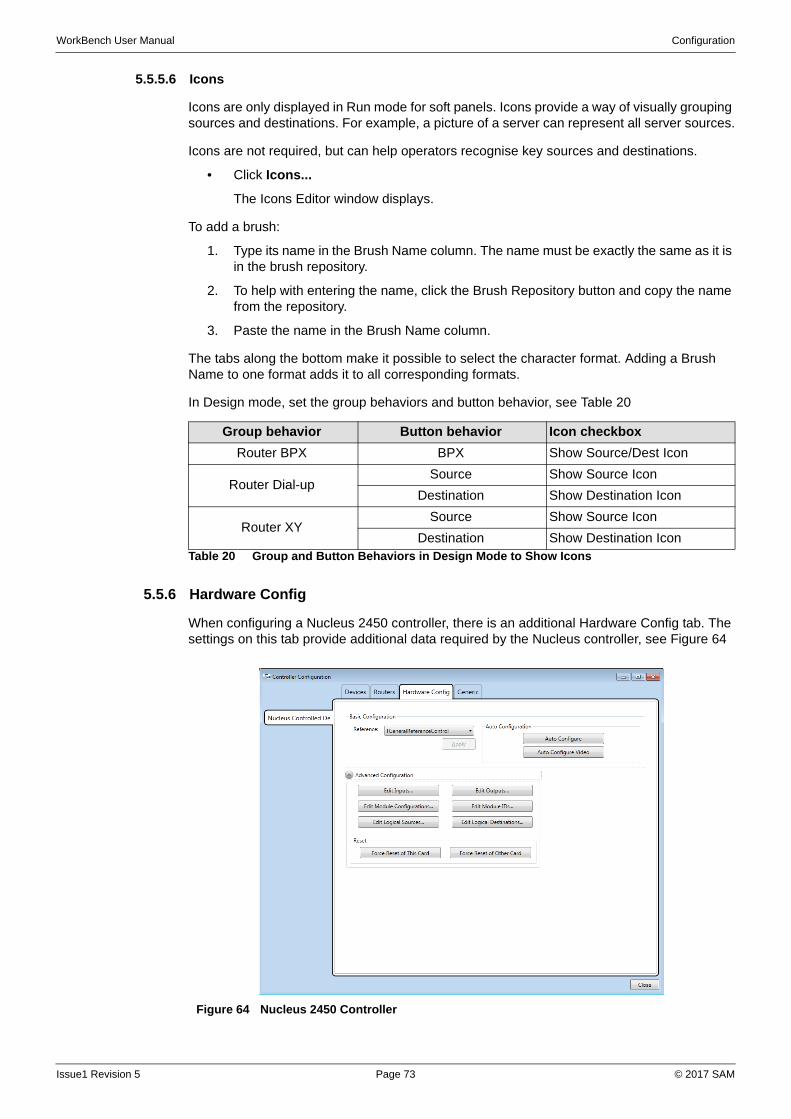
WorkBench User Manual Configuration
5.5.5.6 Icons
Icons are only displayed in Run mode for soft panels. Icons provide a way of visually grouping sources and destinations. For example, a picture of a server can represent all server sources.
Icons are not required, but can help operators recognise key sources and destinations.
• Click Icons...
The Icons Editor window displays.
To add a brush:
1. Type its name in the Brush Name column. The name must be exactly the same as it is in the brush repository.
2. To help with entering the name, click the Brush Repository button and copy the name from the repository.
3. Paste the name in the Brush Name column.
The tabs along the bottom make it possible to select the character format. Adding a Brush Name to one format adds it to all corresponding formats.
In Design mode, set the group behaviors and button behavior, see Table 20
5.5.6 Hardware Config
When configuring a Nucleus 2450 controller, there is an additional Hardware Config tab. The settings on this tab provide additional data required by the Nucleus controller, see Figure 64
Group behavior Button behavior Icon checkbox
Router BPX BPX Show Source/Dest Icon
Router Dial-upSource Show Source Icon
Destination Show Destination Icon
Router XYSource Show Source Icon
Destination Show Destination IconTable 20 Group and Button Behaviors in Design Mode to Show Icons
Figure 64 Nucleus 2450 Controller
Issue1 Revision 5 Page 73 © 2017 SAM
WorkBench User Manual Configuration
The Nucleus 2450 controller can be fitted to Pyxis, Cygnus, and Sirius 800 range of routers.
5.5.6.1 Auto Configuration
In the Configuration section, the Reference drop-down list specifies the reference control type. If the Nucleus card is controlling a Cygnus router, set it to TCygnusReferenceControl, for anything else, set it to TGeneralReferenceControl.
Auto Configure and Auto Configure Video
The auto-configure option is used to configure the settings for the Nucleus controller. To auto-configure the settings, connect to the controller and click the Auto Configure Video button. Workbench configures these settings based on the detected physical inputs, outputs, and modules.These read back from the matrix the ports and modules installed, and update the configure port and modules.
Auto Configure Video also populates the logical to physical source and destination tables. It configures them to all be of type video with a 1 to 1 mapping so that the physical sources / destinations match the logical sources / destinations.
Auto Configure updates the ports and modules but leaves the logical to physical mapping unchanged. This is often used for audio routers where the logical to physical can be used to configure the router as either stereo or mono. It is also useful if a custom logical-to-physical mapping has been configured on a video router and a reconfigure is required without changing this.
5.5.6.2 Advanced Configuration
Input Ports
If the auto-configure option is used, the number and type of ports are set automatically. Any input ports that are not present, or not recognized, are identified as TUnknownInput.
To manually configure physical input ports:
1. In the Number of Ports text field, type the number of physical input ports and then click Apply. The specified number of ports is added to the table.
2. For each input port, select the input type from the drop-down list. Continue adding the input ports in this manner until complete. Or, use the copy and paste function to complete the entries.
3. Click Apply or OK.
Output Ports
To specify or modify the number and types of physical output ports, click Edit Outputs…
If the auto-configure option is used, the number and type of ports are automatically set up. Any output ports that are not present or not recognized are identified as TUnknownOutput.
To manually configure physical output ports:
1. In the Number of Ports text field, enter the number of physical output ports and then click Apply. The specified number of ports is added to the table.
2. For each output port, select the output type from the drop-down list. Continue adding the output ports in this manner until complete. Or, use the copy and paste function to complete the entries.
3. Click Apply or OK.
Note: If Workbench is not connected to the Nucleus card, the auto-configuration option cannot be used. In this case, these settings can either be entered manually or copy and paste the configuration from a spreadsheet.
Issue1 Revision 5 Page 74 © 2017 SAM
WorkBench User Manual Configuration
Module Configurations
For module configurations for each type of router, see “Routers Reference” on page 215.
To manually set up module configurations:
1. In the Number of Configurations text field, enter the number of module configurations and then click Apply. The specified number of configurations is added to the table.
2. For each configuration, select the type from the drop-down list. Continue adding the configurations in this manner until complete. Or, use the copy and paste function to complete the entries.
3. Click Apply or OK.
Module IDs
• Click Edit Module IDs... to specify the number and types of module IDs.
If the auto-configuration option is used, the number and types of module IDs are automatically set up. The only Module ID available is TGeneralModuleID.
There are a few rules that should be adhered to when entering logical sources and destinations.
• The number of physical sources / destinations entered should be based on the signal type selected:
Video and Audio Mono - 1
Audio Stereo - 2
Audio Dolby E - 6
Additional sources / destinations are ignored.
• Physical sources / destinations should be unique. Entering the same physical source / destination for more then one logical source / destination could result in incorrect tally information.
• The physical source / destination relates to the input and output ports. Therefore, the physical source / destination number specified must be in range of the input / output ports.
• It is not possible to use the logical to physical mappings to configure destinations to follow other destinations because additional source / destinations are ignored. However, one destination can be set to follow another with the Generic Editor, Destination Follow.
Note: The term module refers to the card in a router on which the physical inputs and outputs are situated.
Note: If the auto-configuration option is used, the number and types of module configurations are automatically set. Any modules that are not present or not recognized are identified as TUnknownModule.
Issue1 Revision 5 Page 75 © 2017 SAM

WorkBench User Manual Configuration
Logical Sources
• To specify the logical sources, click Edit Logical Sources...
In instances where a signal that comprises more than one physical source, such as the left and right channels of a stereo pair, logical sources are used to identify that they should be routed together. Logical sources can be made up of between one and six physical input sources.
If the auto-configure option is used, the logical sources are automatically set up.
To manually configure logical sources:
1. In the Number of Sources, type the required number of logical sources and then click Apply. The specified number of logical sources are added to the table. For each logical source, select the signal type from the drop-down list and then type the physical sources that are comprised by the logical source in the Phy 1 to Phy 6 fields. Continue adding the logical sources in this manner until complete, or use the copy and paste function to complete the entries.
2. Click Apply or OK.
Logical Destinations
• Click Edit Logical Destinations... to specify the logical destinations.
In instances where a signal that comprises more than one physical destination, such as the left and right channels of a stereo pair, logical destinations are used to identify that they should be routed together. Logical destinations can be made up of between one and six physical outputs.
If the auto-configure option is used, the logical destinations are automatically set up.
To manually configure logical destinations:
1. In the Number of Destinations text field, type the required number of logical destinations and then click Apply. The specified number of logical destinations is added to the table.
2. For each logical destination, select the signal type from the drop-down list and then enter the physical outputs that are comprised by the logical destination in the Phy 1 to Phy 6 fields. Continue adding the logical destinations in this manner until complete. Or, use the copy and paste function to complete the entries.
3. Click Apply or OK.
Force Reset of This Card
To ensure that changes are made to a card, after pushing a database, click the Force Reset of This Card (also available on the main configuration screen).
Force Reset of Other Card
This is only relevant in a dual controller system. It connects to one controller and force a reset on the other controller. For example, in a dual controller system when the database has been loaded into the controller, this resets the other controller so that it becomes active.
Issue1 Revision 5 Page 76 © 2017 SAM
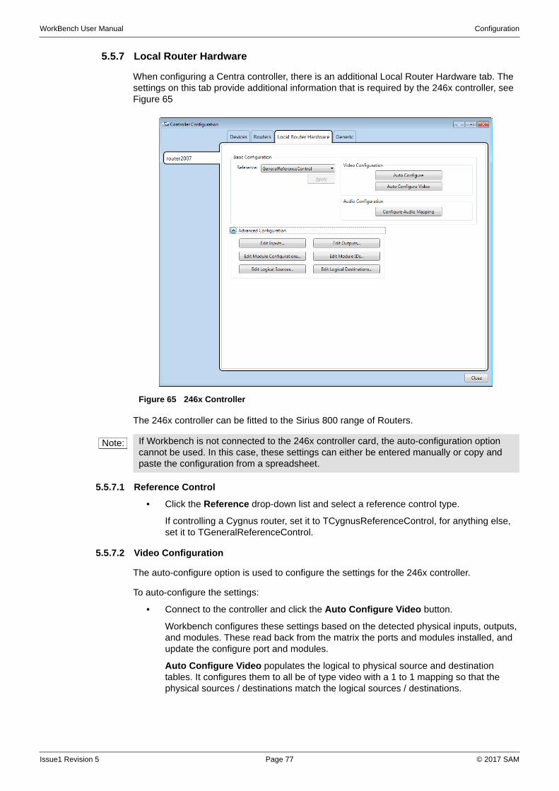
WorkBench User Manual Configuration
5.5.7 Local Router Hardware
When configuring a Centra controller, there is an additional Local Router Hardware tab. The settings on this tab provide additional information that is required by the 246x controller, see Figure 65
The 246x controller can be fitted to the Sirius 800 range of Routers.
5.5.7.1 Reference Control
• Click the Reference drop-down list and select a reference control type.
If controlling a Cygnus router, set it to TCygnusReferenceControl, for anything else, set it to TGeneralReferenceControl.
5.5.7.2 Video Configuration
The auto-configure option is used to configure the settings for the 246x controller.
To auto-configure the settings:
• Connect to the controller and click the Auto Configure Video button.
Workbench configures these settings based on the detected physical inputs, outputs, and modules. These read back from the matrix the ports and modules installed, and update the configure port and modules.
Auto Configure Video populates the logical to physical source and destination tables. It configures them to all be of type video with a 1 to 1 mapping so that the physical sources / destinations match the logical sources / destinations.
Figure 65 246x Controller
Note: If Workbench is not connected to the 246x controller card, the auto-configuration option cannot be used. In this case, these settings can either be entered manually or copy and paste the configuration from a spreadsheet.
Issue1 Revision 5 Page 77 © 2017 SAM
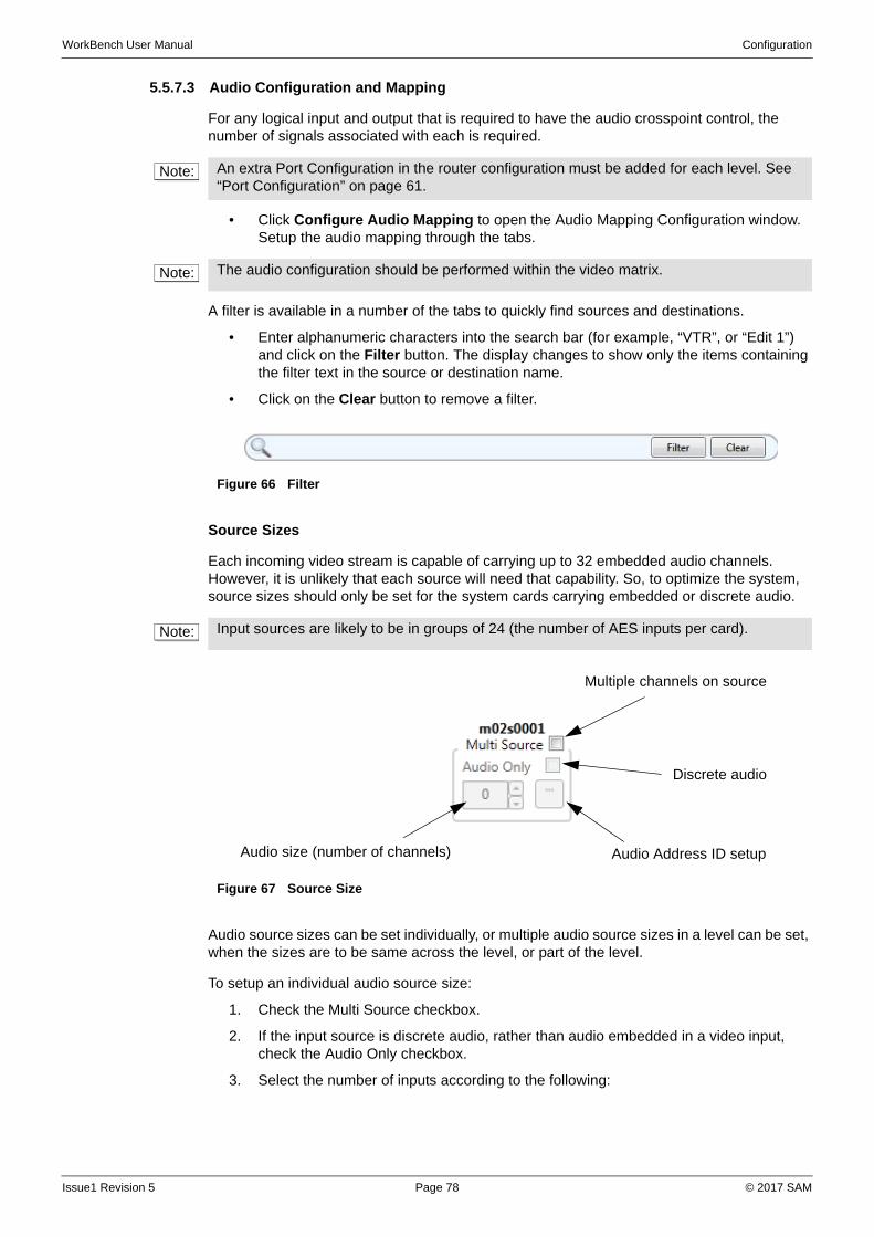
WorkBench User Manual Configuration
5.5.7.3 Audio Configuration and Mapping
For any logical input and output that is required to have the audio crosspoint control, the number of signals associated with each is required.
• Click Configure Audio Mapping to open the Audio Mapping Configuration window. Setup the audio mapping through the tabs.
A filter is available in a number of the tabs to quickly find sources and destinations.
• Enter alphanumeric characters into the search bar (for example, “VTR”, or “Edit 1”) and click on the Filter button. The display changes to show only the items containing the filter text in the source or destination name.
• Click on the Clear button to remove a filter.
Source Sizes
Each incoming video stream is capable of carrying up to 32 embedded audio channels. However, it is unlikely that each source will need that capability. So, to optimize the system, source sizes should only be set for the system cards carrying embedded or discrete audio.
Audio source sizes can be set individually, or multiple audio source sizes in a level can be set, when the sizes are to be same across the level, or part of the level.
To setup an individual audio source size:
1. Check the Multi Source checkbox.
2. If the input source is discrete audio, rather than audio embedded in a video input, check the Audio Only checkbox.
3. Select the number of inputs according to the following:
Note: An extra Port Configuration in the router configuration must be added for each level. See “Port Configuration” on page 61.
Note: The audio configuration should be performed within the video matrix.
Figure 66 Filter
Note: Input sources are likely to be in groups of 24 (the number of AES inputs per card).
Figure 67 Source Size
Multiple channels on source
Discrete audio
Audio Address ID setupAudio size (number of channels)
Issue1 Revision 5 Page 78 © 2017 SAM
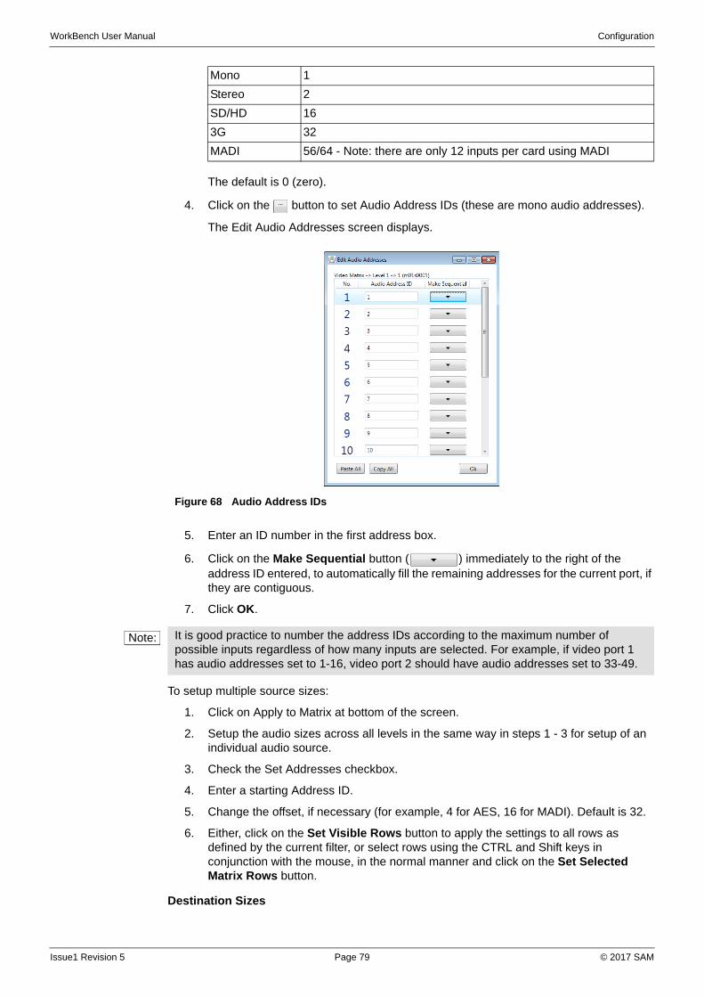
WorkBench User Manual Configuration
The default is 0 (zero).
4. Click on the button to set Audio Address IDs (these are mono audio addresses).
The Edit Audio Addresses screen displays.
5. Enter an ID number in the first address box.
6. Click on the Make Sequential button ( ) immediately to the right of the address ID entered, to automatically fill the remaining addresses for the current port, if they are contiguous.
7. Click OK.
To setup multiple source sizes:
1. Click on Apply to Matrix at bottom of the screen.
2. Setup the audio sizes across all levels in the same way in steps 1 - 3 for setup of an individual audio source.
3. Check the Set Addresses checkbox.
4. Enter a starting Address ID.
5. Change the offset, if necessary (for example, 4 for AES, 16 for MADI). Default is 32.
6. Either, click on the Set Visible Rows button to apply the settings to all rows as defined by the current filter, or select rows using the CTRL and Shift keys in conjunction with the mouse, in the normal manner and click on the Set Selected Matrix Rows button.
Destination Sizes
Mono 1
Stereo 2
SD/HD 16
3G 32
MADI 56/64 - Note: there are only 12 inputs per card using MADI
Figure 68 Audio Address IDs
Note: It is good practice to number the address IDs according to the maximum number of possible inputs regardless of how many inputs are selected. For example, if video port 1 has audio addresses set to 1-16, video port 2 should have audio addresses set to 33-49.
Issue1 Revision 5 Page 79 © 2017 SAM
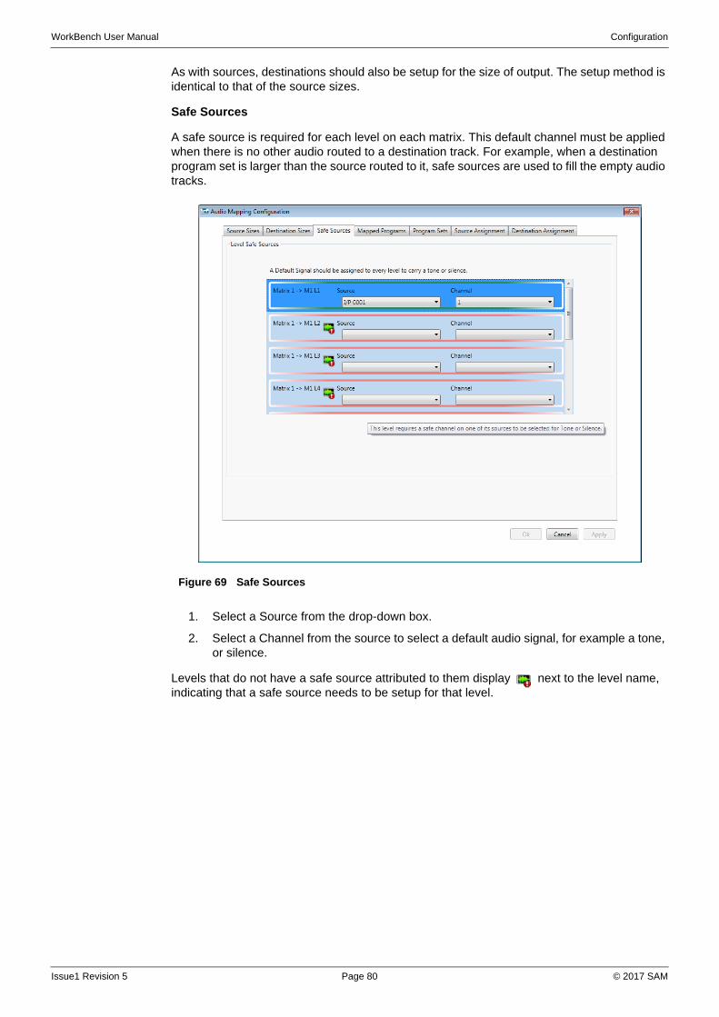
WorkBench User Manual Configuration
As with sources, destinations should also be setup for the size of output. The setup method is identical to that of the source sizes.
Safe Sources
A safe source is required for each level on each matrix. This default channel must be applied when there is no other audio routed to a destination track. For example, when a destination program set is larger than the source routed to it, safe sources are used to fill the empty audio tracks.
1. Select a Source from the drop-down box.
2. Select a Channel from the source to select a default audio signal, for example a tone, or silence.
Levels that do not have a safe source attributed to them display next to the level name, indicating that a safe source needs to be setup for that level.
Figure 69 Safe Sources
Issue1 Revision 5 Page 80 © 2017 SAM
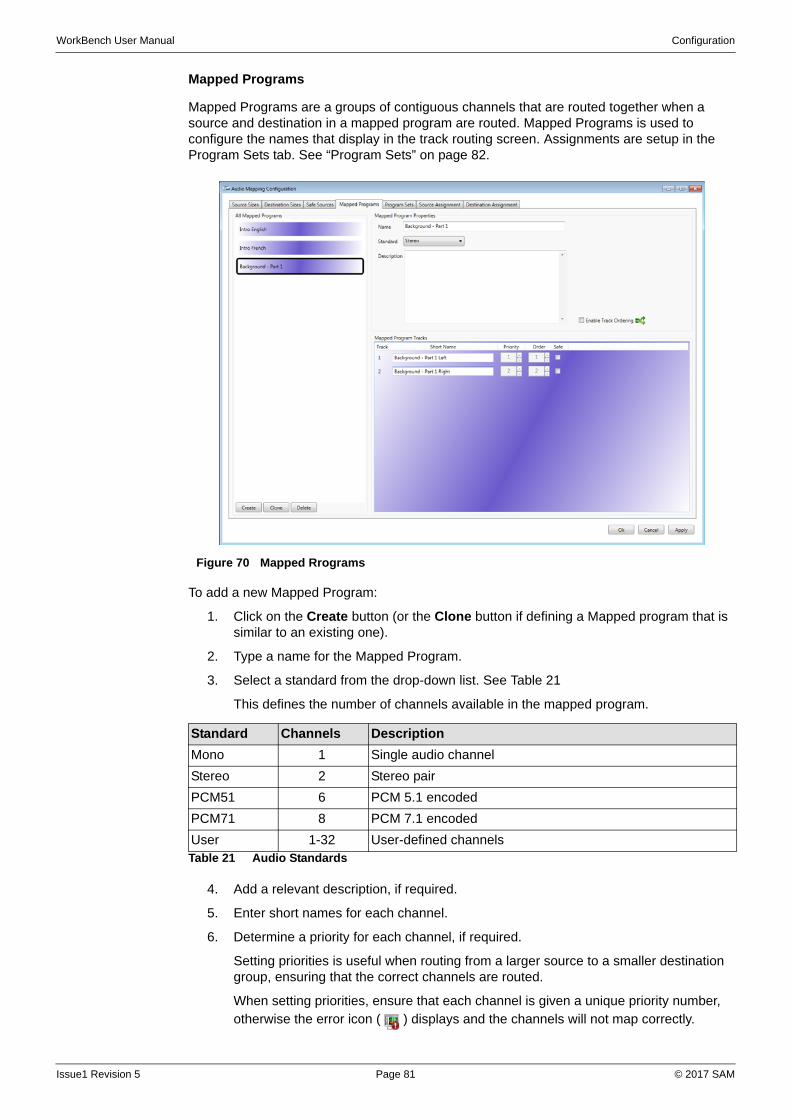
WorkBench User Manual Configuration
Mapped Programs
Mapped Programs are a groups of contiguous channels that are routed together when a source and destination in a mapped program are routed. Mapped Programs is used to configure the names that display in the track routing screen. Assignments are setup in the Program Sets tab. See “Program Sets” on page 82.
To add a new Mapped Program:
1. Click on the Create button (or the Clone button if defining a Mapped program that is similar to an existing one).
2. Type a name for the Mapped Program.
3. Select a standard from the drop-down list. See Table 21
This defines the number of channels available in the mapped program.
4. Add a relevant description, if required.
5. Enter short names for each channel.
6. Determine a priority for each channel, if required.
Setting priorities is useful when routing from a larger source to a smaller destination group, ensuring that the correct channels are routed.
When setting priorities, ensure that each channel is given a unique priority number, otherwise the error icon ( ) displays and the channels will not map correctly.
Figure 70 Mapped Rrograms
Standard Channels Description
Mono 1 Single audio channel
Stereo 2 Stereo pair
PCM51 6 PCM 5.1 encoded
PCM71 8 PCM 7.1 encoded
User 1-32 User-defined channelsTable 21 Audio Standards
Issue1 Revision 5 Page 81 © 2017 SAM
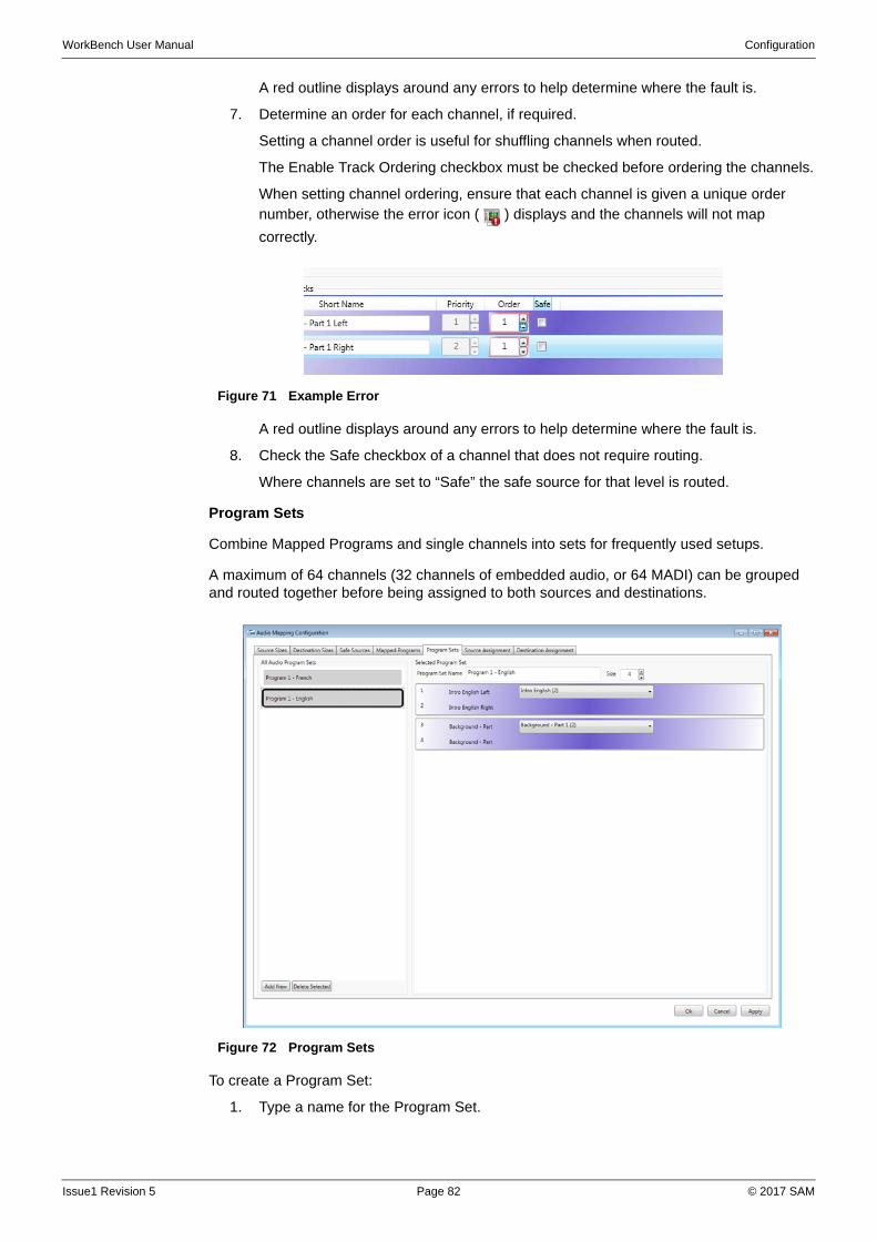
WorkBench User Manual Configuration
A red outline displays around any errors to help determine where the fault is.
7. Determine an order for each channel, if required.
Setting a channel order is useful for shuffling channels when routed.
The Enable Track Ordering checkbox must be checked before ordering the channels.
When setting channel ordering, ensure that each channel is given a unique order number, otherwise the error icon ( ) displays and the channels will not map
correctly.
A red outline displays around any errors to help determine where the fault is.
8. Check the Safe checkbox of a channel that does not require routing.
Where channels are set to “Safe” the safe source for that level is routed.
Program Sets
Combine Mapped Programs and single channels into sets for frequently used setups.
A maximum of 64 channels (32 channels of embedded audio, or 64 MADI) can be grouped and routed together before being assigned to both sources and destinations.
To create a Program Set:
1. Type a name for the Program Set.
Figure 71 Example Error
Figure 72 Program Sets
Issue1 Revision 5 Page 82 © 2017 SAM
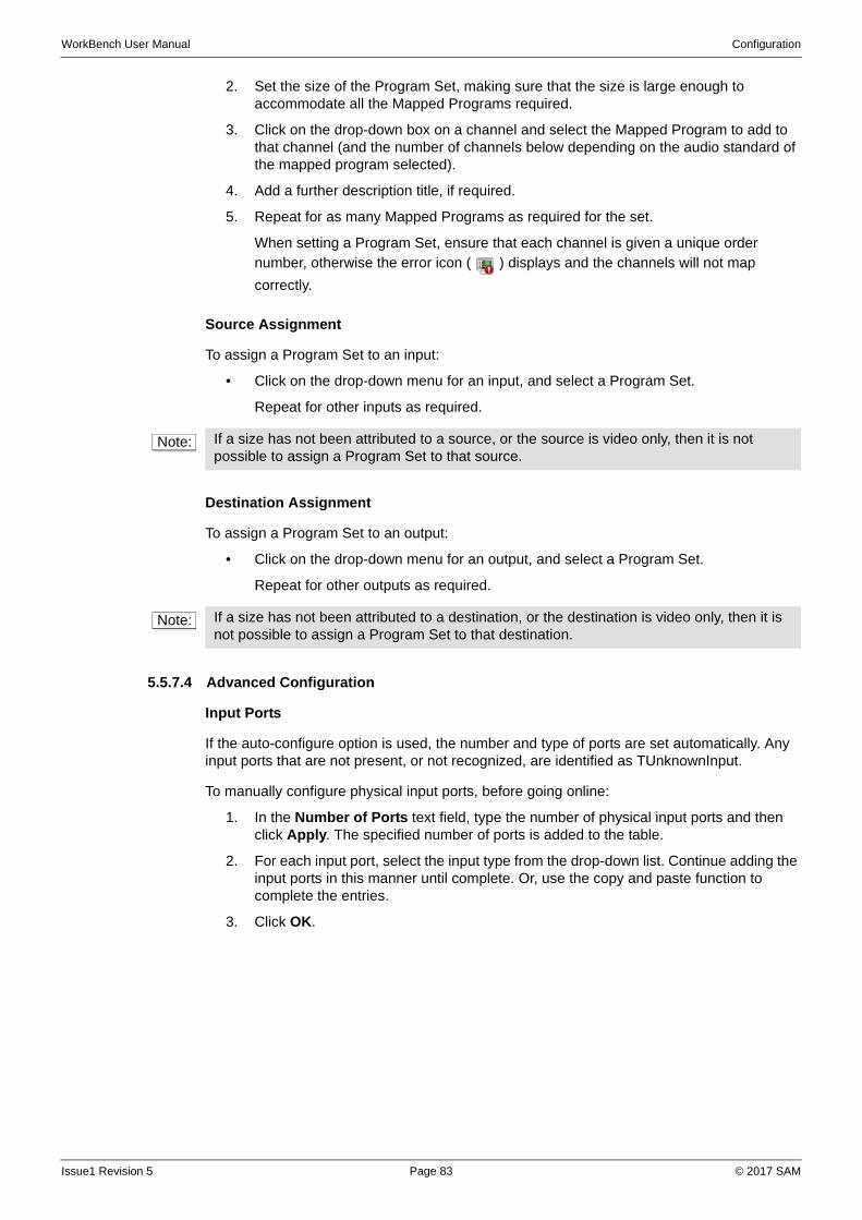
WorkBench User Manual Configuration
2. Set the size of the Program Set, making sure that the size is large enough to accommodate all the Mapped Programs required.
3. Click on the drop-down box on a channel and select the Mapped Program to add to that channel (and the number of channels below depending on the audio standard of the mapped program selected).
4. Add a further description title, if required.
5. Repeat for as many Mapped Programs as required for the set.
When setting a Program Set, ensure that each channel is given a unique order number, otherwise the error icon ( ) displays and the channels will not map
correctly.
Source Assignment
To assign a Program Set to an input:
• Click on the drop-down menu for an input, and select a Program Set.
Repeat for other inputs as required.
Destination Assignment
To assign a Program Set to an output:
• Click on the drop-down menu for an output, and select a Program Set.
Repeat for other outputs as required.
5.5.7.4 Advanced Configuration
Input Ports
If the auto-configure option is used, the number and type of ports are set automatically. Any input ports that are not present, or not recognized, are identified as TUnknownInput.
To manually configure physical input ports, before going online:
1. In the Number of Ports text field, type the number of physical input ports and then click Apply. The specified number of ports is added to the table.
2. For each input port, select the input type from the drop-down list. Continue adding the input ports in this manner until complete. Or, use the copy and paste function to complete the entries.
3. Click OK.
Note: If a size has not been attributed to a source, or the source is video only, then it is not possible to assign a Program Set to that source.
Note: If a size has not been attributed to a destination, or the destination is video only, then it is not possible to assign a Program Set to that destination.
Issue1 Revision 5 Page 83 © 2017 SAM
WorkBench User Manual Configuration
Output Ports
• To specify or modify the number and types of physical output ports, click Edit Outputs…
If the auto-configure option is used, the number and type of ports are automatically set up. Any output ports that are not present or not recognized are identified as TUnknownOutput.
To manually configure physical output ports:
1. In the Number of Ports text field, enter the number of physical output ports and then click Apply. The specified number of ports is added to the table.
2. For each output port, select the output type from the drop-down list. Continue adding the output ports in this manner until complete. Or, use the copy and paste function to complete the entries.
3. Click OK.
Module Configurations
For module configurations for each type of router, see “Routers Reference” on page 215.
To manually set up module configurations:
1. In the Number of Configurations text field, enter the number of module configurations and then click Apply. The specified number of configurations is added to the table.
2. For each configuration, select the type from the drop-down list. Continue adding the configurations in this manner until complete. Or, use the copy and paste function to complete the entries.
3. Click OK.
Module IDs
• Click Edit Module IDs... to specify the number and types of module IDs.
If the auto-configuration option is used, the number and types of module IDs are automatically set up. The only Module ID available is TGeneralModuleID.
There are a few rules that should be adhered to when entering logical sources and destinations.
• The number of physical sources / destinations entered should be based on the signal type selected:
Video and Audio Mono - 1
Audio Stereo - 2
Audio Dolby E - 6
Additional sources / destinations are ignored.
• Physical sources / destinations should be unique. Entering the same physical source / destination for more then one logical source / destination could result in incorrect tally information.
• The physical source / destination relates to the input and output ports, that are defined. Therefore, the physical source / destination number specified must be in range of the input / output ports.
Note: The term module refers to the card in a router on which the physical inputs and outputs are situated.
Note: If the auto-configuration option is used, the number and types of module configurations are automatically set. Any modules that are not present or not recognized are identified as TUnknownModule.
Issue1 Revision 5 Page 84 © 2017 SAM
WorkBench User Manual Configuration
• It is not possible to use the logical to physical mappings to configure destinations to follow other destinations because additional source / destinations are ignored. However, one destination can be set to follow another with the Generic Editor, Destination Follow. See “Generic Editor” on page 100.
Logical Sources
• To specify the logical sources, click Edit Logical Sources...
In instances where a signal that comprises more than one physical source, such as the left and right channels of a stereo pair, logical sources are used to identify that they should be routed together. Logical sources can be made up of between one and six physical input sources.
If the auto-configure option is used, the logical sources are automatically set up.
To manually configure logical sources:
1. In the Number of Sources, type the required number of logical sources and then click Apply. The specified number of logical sources are added to the table. For each logical source, select the signal type from the drop-down list and then type the physical sources that are comprised by the logical source in the Phy 1 to Phy 6 fields. Continue adding the logical sources in this manner until complete, or use the copy and paste function to complete the entries.
2. Click Apply or OK.
Logical Destinations
• Click Edit Logical Destinations... to specify the logical destinations.
In instances where a signal that comprises more than one physical destination, such as the left and right channels of a stereo pair, logical destinations are used to identify that they should be routed together. Logical destinations can be made up of between one and six physical outputs.
If the auto-configure option is used, the logical destinations are automatically set up.
To manually configure logical destinations:
1. In the Number of Destinations text field, type the required number of logical destinations and then click Apply. The specified number of logical destinations is added to the table.
2. For each logical destination, select the signal type from the drop-down list and then enter the physical outputs that are comprised by the logical destination in the Phy 1 to Phy 6 fields. Continue adding the logical destinations in this manner until complete. Or, use the copy and paste function to complete the entries.
3. Click Apply or OK.
Issue1 Revision 5 Page 85 © 2017 SAM
WorkBench User Manual Configuration
Derived References
To configure Derived References offline:
1. Click Edit Derived References... to define internal references derived from the physical reference inputs.
2. Select the Input reference from the drop down list. This will either be a physical input via BNC, or a reference that is derived from another input.
3. Select the required derived reference from the drop-down list.
4. Select the required reference for audio from the drop-down list.
5. Select the reference rate for audio from the drop-down list.
6. Click OK.
5.6 Configuring Panels
5.6.1 Panel Device
A Panel Device relates to a physical hardware device, for example, a control panel. Control panels are configured for use with the router to which they are connected, and then setup using on-screen hardware panel templates.
There are two areas in Workbench that are relevant to Hardware Panels:
• Configuration - A port on a router controller can be configured to communicate with Panel Devices.
When configuring a Hardware Panel, set a router COM port to ptMultiDropFullDuplex.
• Design - The functionality of the Hardware Panels are set in the design mode.
Workbench provides several screen files, each of which is a template for a particular type of panel. These screen files can be imported to Workbench designer so that panels and keypads can be easily configured.
There are several ways to create a hardware panel:
• Configure a router controller to be a panel device, then create the panel through the panels wizard.
• Select one of the pre-defined panels in design mode and link it to a router controller.
• Create a panel in design mode and link it to a router controller.
The hardware panel requires a valid controller, with a panel and keypad, see “Hardware Panels Reference” on page 229.
5.6.1.1 Configuring a Router Controller as a Panel Device
To edit the controller:
1. Open the Configuration window.
To access the Configuration screen, log in as a user with Configuration permissions, see section 4.3.
Note: Derived references are changed online using the relevant run screens (S800 databases only).
Note: For paired controllers, a new panel can only be created for the primary controller.
Note: By default, Run Mode is disabled for hardware panels. Running a hardware panel displays an error stating that the initial screen is disabled. This option is changed in the screen properties window.
Issue1 Revision 5 Page 86 © 2017 SAM
WorkBench User Manual Configuration
2. Select the controller and click the Edit Controller Config ... button. The Controller Configuration window displays. The tabs that are available depend on the type of controller.
3. Select the Devices tab.
4. Check the PanelDevice checkbox.
The Panels configuration has two buttons:
• Add Panel...—starts the Add Hardware Panels Wizard, see section 5.6.1.2.
• Configure Panels...—opens the Hardware Panels Configuration Editor, see section 5.6.1.3.
5.6.1.2 Add Hardware Panel Wizard
The Add Hardware Panel Wizard lists several pre-defined screens for creating a layout that has several parameters already configured.
For each new panel the wizard adds a screen with the following:
• Controller: The behavior of the panel is set to the controller being configured.
• Keypad: Each new keypad is labeled “Keypad1”, “Keypad2”, and so on.
• Panel: Each new panel is labeled “Panel1”, “Panel2”, and so on.
• Source Sequence Set (For XY dial-up and multi-bus panels): New Sequence sets are labeled “Sequence3”, “Sequence4”, and so on.
• Destination Sequence Set (For XY dial-up panels only).
To add a new panel through the wizard:
1. Either select a screen from the list, or click the button to browse to an existing saved screen.
2. Type a name for the panel.
3. Click the Create Screen and Edit Panel button. The wizard displays in Design mode with the selected screen.
Issue1 Revision 5 Page 87 © 2017 SAM
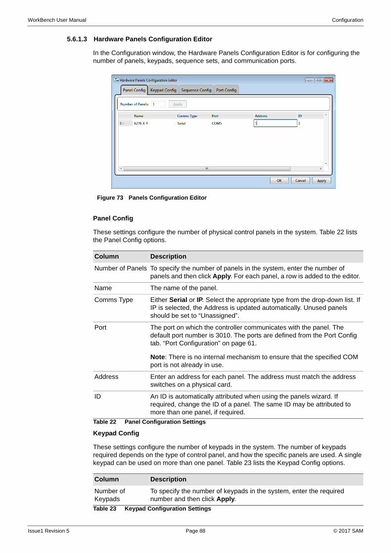
WorkBench User Manual Configuration
5.6.1.3 Hardware Panels Configuration Editor
In the Configuration window, the Hardware Panels Configuration Editor is for configuring the number of panels, keypads, sequence sets, and communication ports.
Panel Config
These settings configure the number of physical control panels in the system. Table 22 lists the Panel Config options.
Keypad Config
These settings configure the number of keypads in the system. The number of keypads required depends on the type of control panel, and how the specific panels are used. A single keypad can be used on more than one panel. Table 23 lists the Keypad Config options.
Figure 73 Panels Configuration Editor
Column Description
Number of Panels To specify the number of panels in the system, enter the number of panels and then click Apply. For each panel, a row is added to the editor.
Name The name of the panel.
Comms Type Either Serial or IP. Select the appropriate type from the drop-down list. If IP is selected, the Address is updated automatically. Unused panels should be set to “Unassigned”.
Port The port on which the controller communicates with the panel. The default port number is 3010. The ports are defined from the Port Config tab. “Port Configuration” on page 61.
Note: There is no internal mechanism to ensure that the specified COM port is not already in use.
Address Enter an address for each panel. The address must match the address switches on a physical card.
ID An ID is automatically attributed when using the panels wizard. If required, change the ID of a panel. The same ID may be attributed to more than one panel, if required.
Table 22 Panel Configuration Settings
Column Description
Number of Keypads
To specify the number of keypads in the system, enter the required number and then click Apply.
Table 23 Keypad Configuration Settings
Issue1 Revision 5 Page 88 © 2017 SAM
WorkBench User Manual Configuration
A dial-up keypad is configured such that a mnemonic or number is assigned to a button. The sources and/or destinations can then be selected by making a single, or series of, button presses to select an input or output.
A keypad that dials up sources only requires a single SourceKeypad sequence set. A keypad that dials up destinations only requires a single DestinationKeypad sequence set. If a panel dials up both sources and destinations, it requires both a SourceKeypad sequence set and a DestinationKeypad sequence set.
Sequence Config
In the Configuration Window, these settings configure the number of sequence sets in the system. Sequence sets group the key sequences (defined in Design mode) that are required to enter sources and destinations. Table 24 lists the Sequence Config options.
Port Config
In the Configuration window, the Hardware Panels - Port Config tab specifies which COM port on the host machine is set to communicate with the controller.
Name The name of the keypad.
Column Description
Number of Sequence Sets
To specify the number of sequence sets available in the system, enter the required number and then click Apply.
Name The name of the sequence set.
Type For each sequence set, select a type from the drop-down list:
• SourceKeypad
• DestinationKeypad
• SoftSourceKeypad
• SoftDestinationKeypad
Table 24 Sequence Configuration Settings
Note: Do not confuse the ports listed in the Hardware Panels Configuration editor with the ports listed in the Router Controller.
Column Description
Available Ports The available COM ports are displayed on the left of the window. Click Interrogate Ports to update the list of available ports.
Note: The list of ports is not automatically updated: Manually interrogate the ports to ensure that the list is up-to-date.
Add Click Add to transfer the port to the Serial Ports Configured section.
Assign To change the configured port, select a port from the Available column and a Configured port, and click Assign.
Serial Ports Configured
For each port in the Serial Ports Configured section, select a Protocol, Baud Rate, and Flags.
Table 25 Port Configuration Settings
Column Description
Table 23 Keypad Configuration Settings
Issue1 Revision 5 Page 89 © 2017 SAM
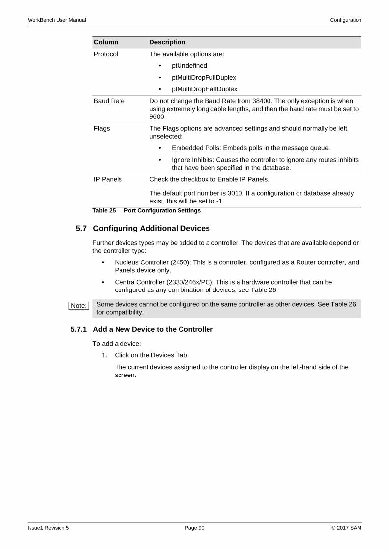
WorkBench User Manual Configuration
5.7 Configuring Additional Devices
Further devices types may be added to a controller. The devices that are available depend on the controller type:
• Nucleus Controller (2450): This is a controller, configured as a Router controller, and Panels device only.
• Centra Controller (2330/246x/PC): This is a hardware controller that can be configured as any combination of devices, see Table 26
5.7.1 Add a New Device to the Controller
To add a device:
1. Click on the Devices Tab.
The current devices assigned to the controller display on the left-hand side of the screen.
Protocol The available options are:
• ptUndefined
• ptMultiDropFullDuplex
• ptMultiDropHalfDuplex
Baud Rate Do not change the Baud Rate from 38400. The only exception is when using extremely long cable lengths, and then the baud rate must be set to 9600.
Flags The Flags options are advanced settings and should normally be left unselected:
• Embedded Polls: Embeds polls in the message queue.
• Ignore Inhibits: Causes the controller to ignore any routes inhibits that have been specified in the database.
IP Panels Check the checkbox to Enable IP Panels.
The default port number is 3010. If a configuration or database already exist, this will be set to -1.
Column Description
Table 25 Port Configuration Settings
Note: Some devices cannot be configured on the same controller as other devices. See Table 26 for compatibility.
Issue1 Revision 5 Page 90 © 2017 SAM
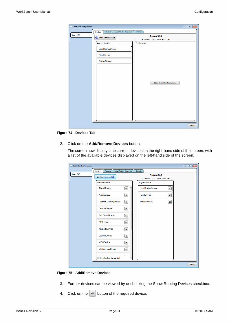
WorkBench User Manual Configuration
2. Click on the Add/Remove Devices button.
The screen now displays the current devices on the right-hand side of the screen, with a list of the available devices displayed on the left-hand side of the screen.
3. Further devices can be viewed by unchecking the Show Routing Devices checkbox.
4. Click on the button of the required device.
Figure 74 Devices Tab
Figure 75 Add/Remove Devices
Issue1 Revision 5 Page 91 © 2017 SAM

WorkBench User Manual Configuration
The device name moves from the Available Devices field to the Assigned Devices field on the screen.
5. Add further devices, if required, in the same manner.
6. Click on the Configure Devices button.
This returns to the previous screen, allowing for configuration of the new device(s).
7. Select the appropriate device, and then click on the relevant Configure..., Edit..., or Add... button on the right-hand side of the screen.
Note: Some devices cannot be configured from this screen, and do not display any buttons on the right-hand side of the screen. Such devices must be configured using the Generic Editor. See “Generic Editor” on page 100.
Issue1 Revision 5 Page 92 © 2017 SAM
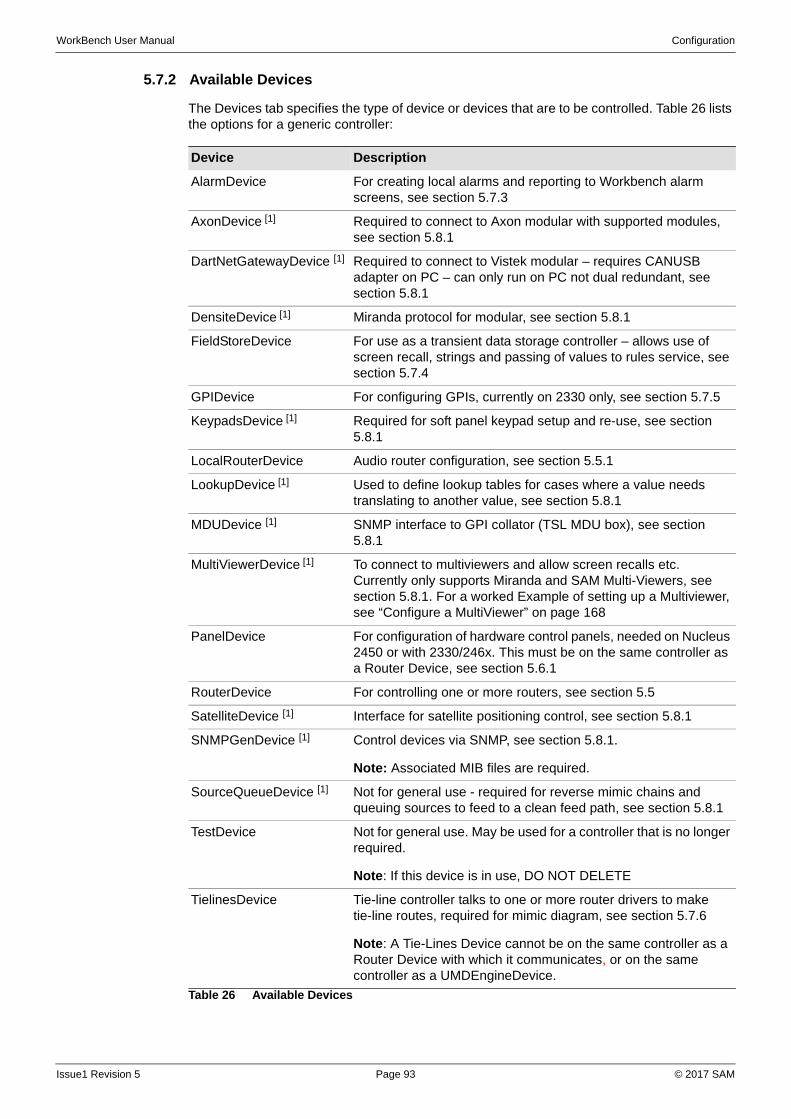
WorkBench User Manual Configuration
5.7.2 Available Devices
The Devices tab specifies the type of device or devices that are to be controlled. Table 26 lists the options for a generic controller:
Device Description
AlarmDevice For creating local alarms and reporting to Workbench alarm screens, see section 5.7.3
AxonDevice [1] Required to connect to Axon modular with supported modules, see section 5.8.1
DartNetGatewayDevice [1] Required to connect to Vistek modular – requires CANUSB adapter on PC – can only run on PC not dual redundant, see section 5.8.1
DensiteDevice [1] Miranda protocol for modular, see section 5.8.1
FieldStoreDevice For use as a transient data storage controller – allows use of screen recall, strings and passing of values to rules service, see section 5.7.4
GPIDevice For configuring GPIs, currently on 2330 only, see section 5.7.5
KeypadsDevice [1] Required for soft panel keypad setup and re-use, see section 5.8.1
LocalRouterDevice Audio router configuration, see section 5.5.1
LookupDevice [1] Used to define lookup tables for cases where a value needs translating to another value, see section 5.8.1
MDUDevice [1] SNMP interface to GPI collator (TSL MDU box), see section 5.8.1
MultiViewerDevice [1] To connect to multiviewers and allow screen recalls etc. Currently only supports Miranda and SAM Multi-Viewers, see section 5.8.1. For a worked Example of setting up a Multiviewer, see “Configure a MultiViewer” on page 168
PanelDevice For configuration of hardware control panels, needed on Nucleus 2450 or with 2330/246x. This must be on the same controller as a Router Device, see section 5.6.1
RouterDevice For controlling one or more routers, see section 5.5
SatelliteDevice [1] Interface for satellite positioning control, see section 5.8.1
SNMPGenDevice [1] Control devices via SNMP, see section 5.8.1.
Note: Associated MIB files are required.
SourceQueueDevice [1] Not for general use - required for reverse mimic chains and queuing sources to feed to a clean feed path, see section 5.8.1
TestDevice Not for general use. May be used for a controller that is no longer required.
Note: If this device is in use, DO NOT DELETE
TielinesDevice Tie-line controller talks to one or more router drivers to make tie-line routes, required for mimic diagram, see section 5.7.6
Note: A Tie-Lines Device cannot be on the same controller as a Router Device with which it communicates, or on the same controller as a UMDEngineDevice.
Table 26 Available Devices
Issue1 Revision 5 Page 93 © 2017 SAM
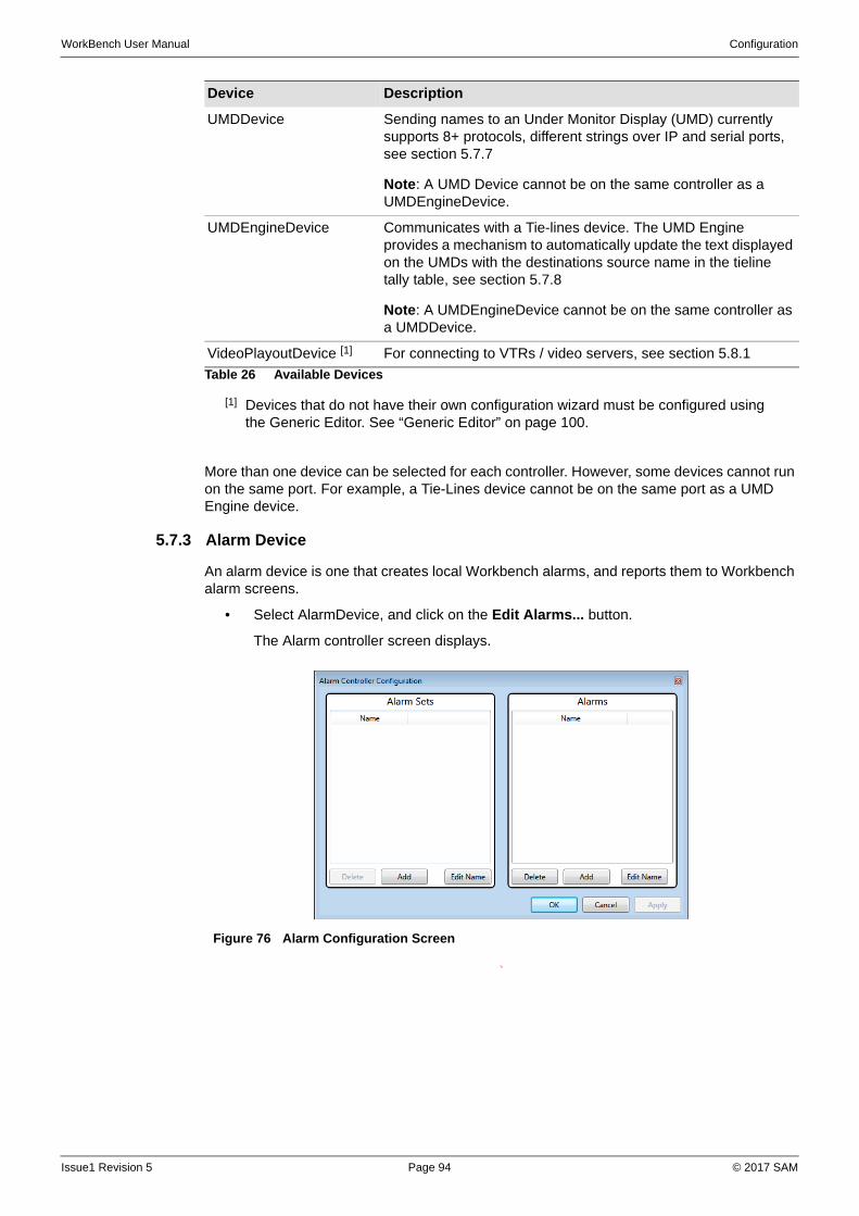
WorkBench User Manual Configuration
More than one device can be selected for each controller. However, some devices cannot run on the same port. For example, a Tie-Lines device cannot be on the same port as a UMD Engine device.
5.7.3 Alarm Device
An alarm device is one that creates local Workbench alarms, and reports them to Workbench alarm screens.
• Select AlarmDevice, and click on the Edit Alarms... button.
The Alarm controller screen displays.
To
UMDDevice Sending names to an Under Monitor Display (UMD) currently supports 8+ protocols, different strings over IP and serial ports, see section 5.7.7
Note: A UMD Device cannot be on the same controller as a UMDEngineDevice.
UMDEngineDevice Communicates with a Tie-lines device. The UMD Engine provides a mechanism to automatically update the text displayed on the UMDs with the destinations source name in the tieline tally table, see section 5.7.8
Note: A UMDEngineDevice cannot be on the same controller as a UMDDevice.
VideoPlayoutDevice [1] For connecting to VTRs / video servers, see section 5.8.1
[1] Devices that do not have their own configuration wizard must be configured using the Generic Editor. See “Generic Editor” on page 100.
Device Description
Table 26 Available Devices
Figure 76 Alarm Configuration Screen
Issue1 Revision 5 Page 94 © 2017 SAM
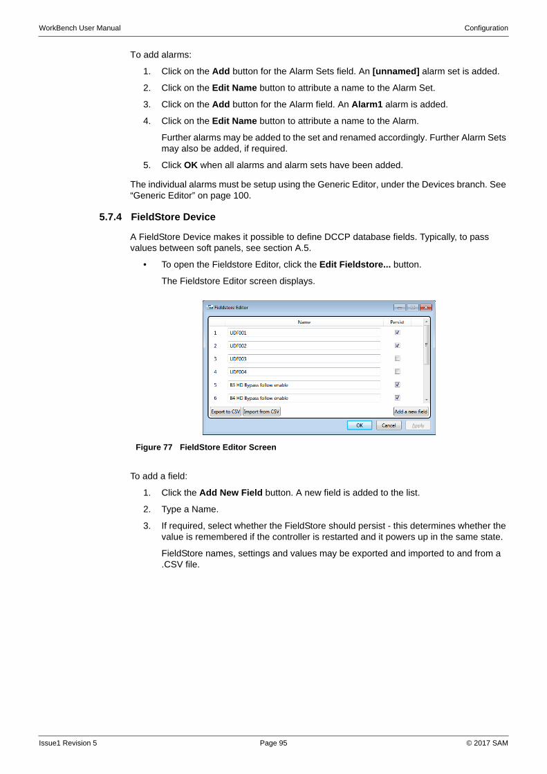
WorkBench User Manual Configuration
To add alarms:
1. Click on the Add button for the Alarm Sets field. An [unnamed] alarm set is added.
2. Click on the Edit Name button to attribute a name to the Alarm Set.
3. Click on the Add button for the Alarm field. An Alarm1 alarm is added.
4. Click on the Edit Name button to attribute a name to the Alarm.
Further alarms may be added to the set and renamed accordingly. Further Alarm Sets may also be added, if required.
5. Click OK when all alarms and alarm sets have been added.
The individual alarms must be setup using the Generic Editor, under the Devices branch. See “Generic Editor” on page 100.
5.7.4 FieldStore Device
A FieldStore Device makes it possible to define DCCP database fields. Typically, to pass values between soft panels, see section A.5.
• To open the Fieldstore Editor, click the Edit Fieldstore... button.
The Fieldstore Editor screen displays.
To add a field:
1. Click the Add New Field button. A new field is added to the list.
2. Type a Name.
3. If required, select whether the FieldStore should persist - this determines whether the value is remembered if the controller is restarted and it powers up in the same state.
FieldStore names, settings and values may be exported and imported to and from a .CSV file.
Figure 77 FieldStore Editor Screen
Issue1 Revision 5 Page 95 © 2017 SAM
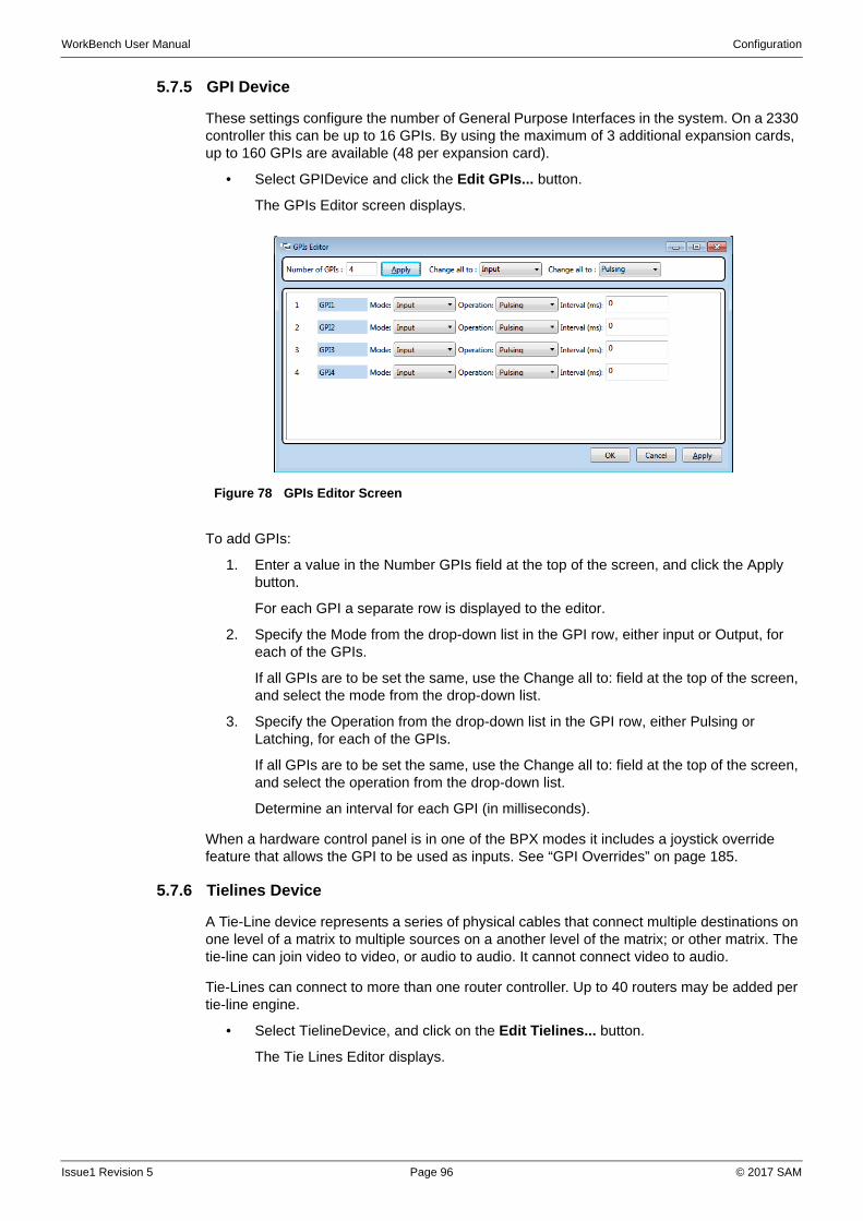
WorkBench User Manual Configuration
5.7.5 GPI Device
These settings configure the number of General Purpose Interfaces in the system. On a 2330 controller this can be up to 16 GPIs. By using the maximum of 3 additional expansion cards, up to 160 GPIs are available (48 per expansion card).
• Select GPIDevice and click the Edit GPIs... button.
The GPIs Editor screen displays.
To add GPIs:
1. Enter a value in the Number GPIs field at the top of the screen, and click the Apply button.
For each GPI a separate row is displayed to the editor.
2. Specify the Mode from the drop-down list in the GPI row, either input or Output, for each of the GPIs.
If all GPIs are to be set the same, use the Change all to: field at the top of the screen, and select the mode from the drop-down list.
3. Specify the Operation from the drop-down list in the GPI row, either Pulsing or Latching, for each of the GPIs.
If all GPIs are to be set the same, use the Change all to: field at the top of the screen, and select the operation from the drop-down list.
Determine an interval for each GPI (in milliseconds).
When a hardware control panel is in one of the BPX modes it includes a joystick override feature that allows the GPI to be used as inputs. See “GPI Overrides” on page 185.
5.7.6 Tielines Device
A Tie-Line device represents a series of physical cables that connect multiple destinations on one level of a matrix to multiple sources on a another level of the matrix; or other matrix. The tie-line can join video to video, or audio to audio. It cannot connect video to audio.
Tie-Lines can connect to more than one router controller. Up to 40 routers may be added per tie-line engine.
• Select TielineDevice, and click on the Edit Tielines... button.
The Tie Lines Editor displays.
Figure 78 GPIs Editor Screen
Issue1 Revision 5 Page 96 © 2017 SAM
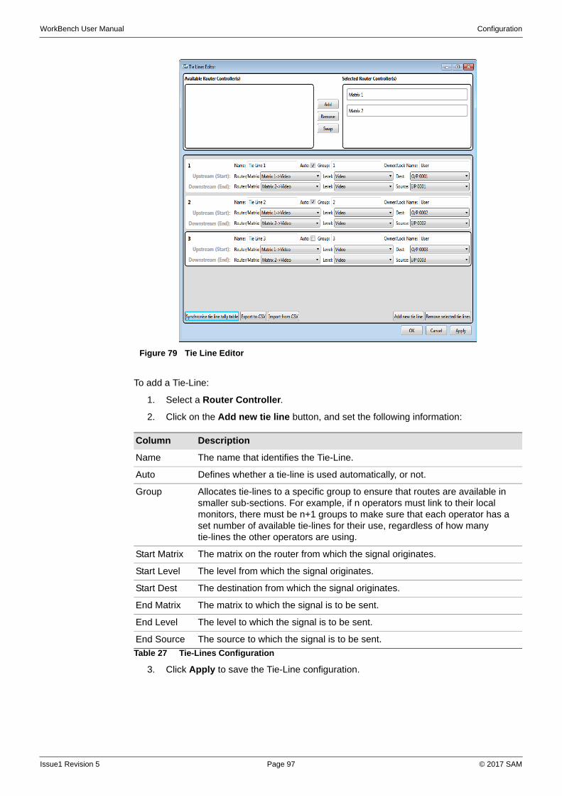
WorkBench User Manual Configuration
To add a Tie-Line:
1. Select a Router Controller.
2. Click on the Add new tie line button, and set the following information:
3. Click Apply to save the Tie-Line configuration.
Figure 79 Tie Line Editor
Column Description
Name The name that identifies the Tie-Line.
Auto Defines whether a tie-line is used automatically, or not.
Group Allocates tie-lines to a specific group to ensure that routes are available in smaller sub-sections. For example, if n operators must link to their local monitors, there must be n+1 groups to make sure that each operator has a set number of available tie-lines for their use, regardless of how many tie-lines the other operators are using.
Start Matrix The matrix on the router from which the signal originates.
Start Level The level from which the signal originates.
Start Dest The destination from which the signal originates.
End Matrix The matrix to which the signal is to be sent.
End Level The level to which the signal is to be sent.
End Source The source to which the signal is to be sent.
Table 27 Tie-Lines Configuration
Issue1 Revision 5 Page 97 © 2017 SAM
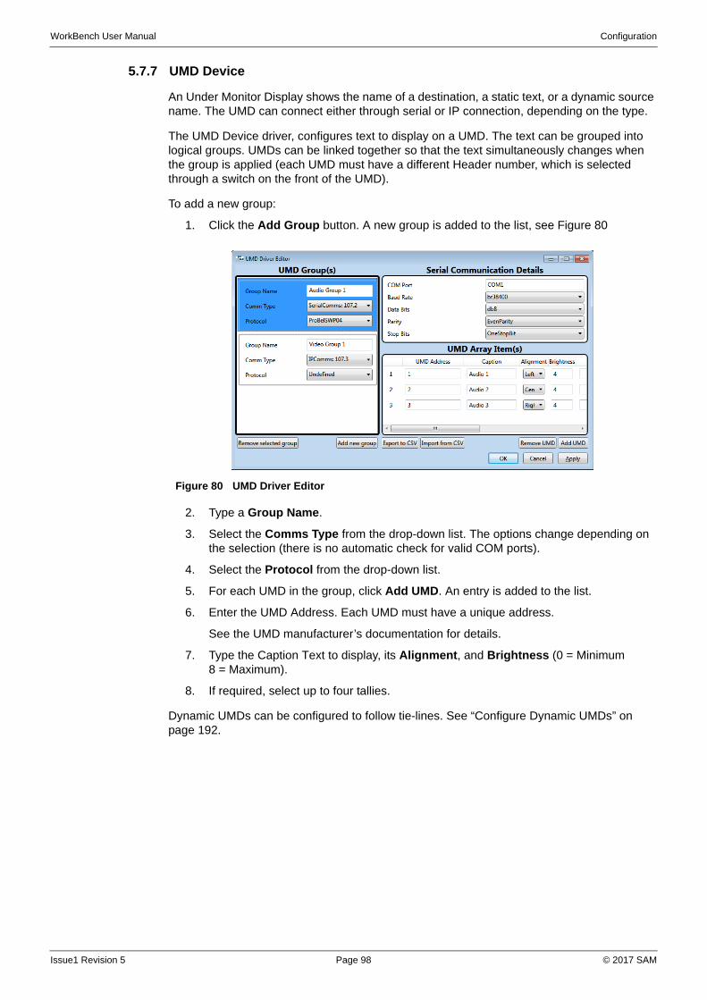
WorkBench User Manual Configuration
5.7.7 UMD Device
An Under Monitor Display shows the name of a destination, a static text, or a dynamic source name. The UMD can connect either through serial or IP connection, depending on the type.
The UMD Device driver, configures text to display on a UMD. The text can be grouped into logical groups. UMDs can be linked together so that the text simultaneously changes when the group is applied (each UMD must have a different Header number, which is selected through a switch on the front of the UMD).
To add a new group:
1. Click the Add Group button. A new group is added to the list, see Figure 80
2. Type a Group Name.
3. Select the Comms Type from the drop-down list. The options change depending on the selection (there is no automatic check for valid COM ports).
4. Select the Protocol from the drop-down list.
5. For each UMD in the group, click Add UMD. An entry is added to the list.
6. Enter the UMD Address. Each UMD must have a unique address.
See the UMD manufacturer’s documentation for details.
7. Type the Caption Text to display, its Alignment, and Brightness (0 = Minimum 8 = Maximum).
8. If required, select up to four tallies.
Dynamic UMDs can be configured to follow tie-lines. See “Configure Dynamic UMDs” on page 192.
Figure 80 UMD Driver Editor
Issue1 Revision 5 Page 98 © 2017 SAM
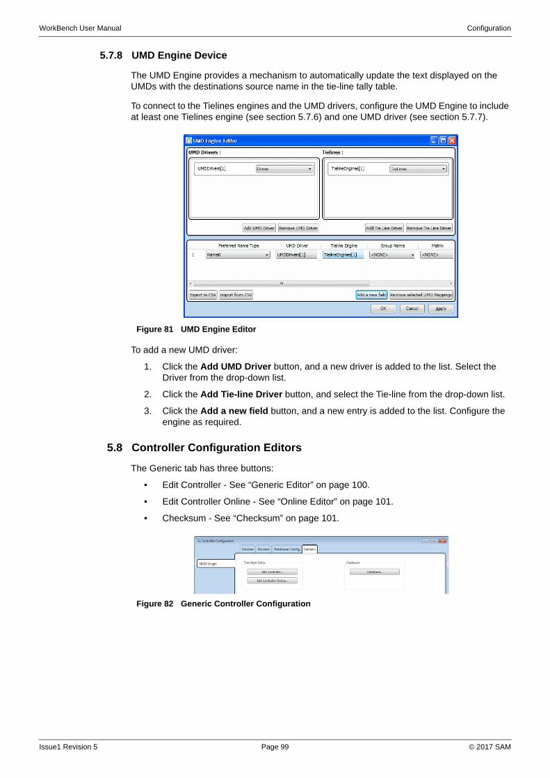
WorkBench User Manual Configuration
5.7.8 UMD Engine Device
The UMD Engine provides a mechanism to automatically update the text displayed on the UMDs with the destinations source name in the tie-line tally table.
To connect to the Tielines engines and the UMD drivers, configure the UMD Engine to include at least one Tielines engine (see section 5.7.6) and one UMD driver (see section 5.7.7).
To add a new UMD driver:
1. Click the Add UMD Driver button, and a new driver is added to the list. Select the Driver from the drop-down list.
2. Click the Add Tie-line Driver button, and select the Tie-line from the drop-down list.
3. Click the Add a new field button, and a new entry is added to the list. Configure the engine as required.
5.8 Controller Configuration Editors
The Generic tab has three buttons:
• Edit Controller - See “Generic Editor” on page 100.
• Edit Controller Online - See “Online Editor” on page 101.
• Checksum - See “Checksum” on page 101.
Figure 81 UMD Engine Editor
Figure 82 Generic Controller Configuration
Issue1 Revision 5 Page 99 © 2017 SAM
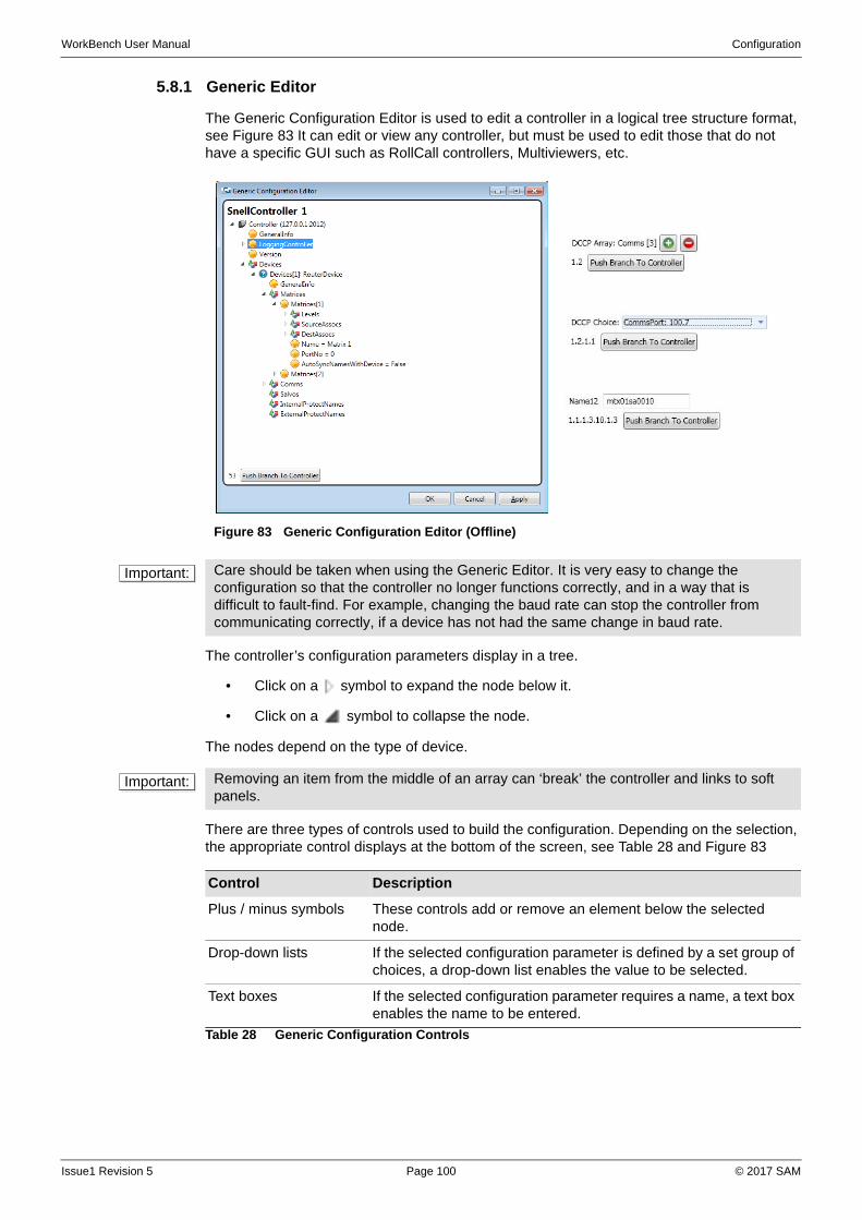
WorkBench User Manual Configuration
5.8.1 Generic Editor
The Generic Configuration Editor is used to edit a controller in a logical tree structure format, see Figure 83 It can edit or view any controller, but must be used to edit those that do not have a specific GUI such as RollCall controllers, Multiviewers, etc.
The controller’s configuration parameters display in a tree.
• Click on a symbol to expand the node below it.
• Click on a symbol to collapse the node.
The nodes depend on the type of device.
There are three types of controls used to build the configuration. Depending on the selection, the appropriate control displays at the bottom of the screen, see Table 28 and Figure 83
Figure 83 Generic Configuration Editor (Offline)
Important: Care should be taken when using the Generic Editor. It is very easy to change the configuration so that the controller no longer functions correctly, and in a way that is difficult to fault-find. For example, changing the baud rate can stop the controller from communicating correctly, if a device has not had the same change in baud rate.
Important: Removing an item from the middle of an array can ‘break’ the controller and links to soft panels.
Control Description
Plus / minus symbols These controls add or remove an element below the selected node.
Drop-down lists If the selected configuration parameter is defined by a set group of choices, a drop-down list enables the value to be selected.
Text boxes If the selected configuration parameter requires a name, a text box enables the name to be entered.
Table 28 Generic Configuration Controls
Issue1 Revision 5 Page 100 © 2017 SAM
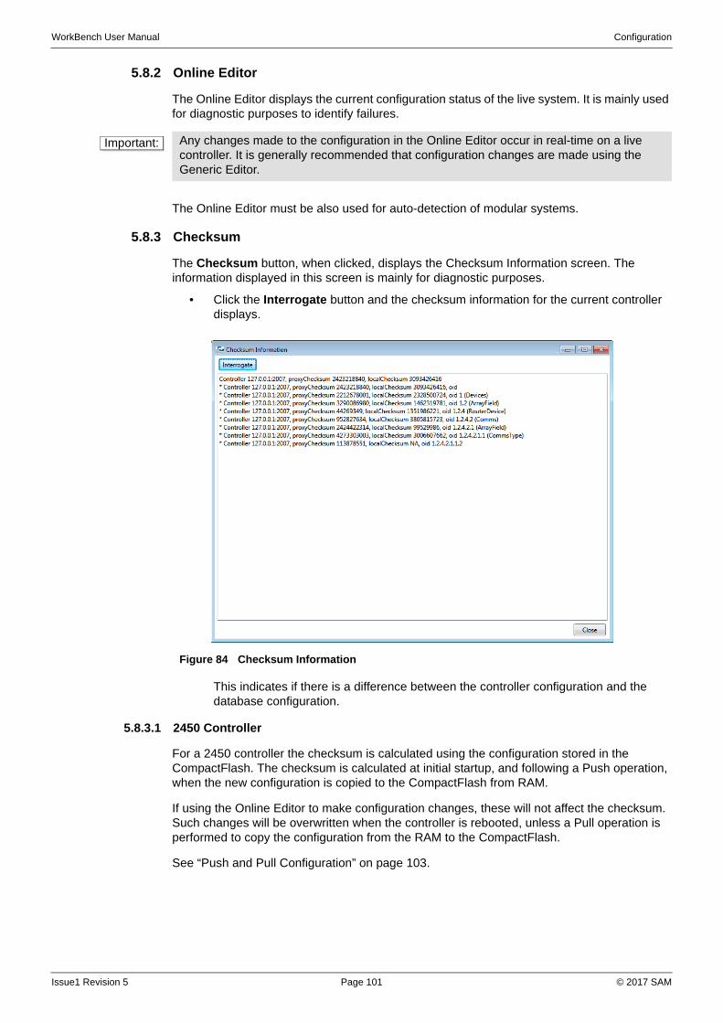
WorkBench User Manual Configuration
5.8.2 Online Editor
The Online Editor displays the current configuration status of the live system. It is mainly used for diagnostic purposes to identify failures.
The Online Editor must be also used for auto-detection of modular systems.
5.8.3 Checksum
The Checksum button, when clicked, displays the Checksum Information screen. The information displayed in this screen is mainly for diagnostic purposes.
• Click the Interrogate button and the checksum information for the current controller displays.
This indicates if there is a difference between the controller configuration and the database configuration.
5.8.3.1 2450 Controller
For a 2450 controller the checksum is calculated using the configuration stored in the CompactFlash. The checksum is calculated at initial startup, and following a Push operation, when the new configuration is copied to the CompactFlash from RAM.
If using the Online Editor to make configuration changes, these will not affect the checksum. Such changes will be overwritten when the controller is rebooted, unless a Pull operation is performed to copy the configuration from the RAM to the CompactFlash.
See “Push and Pull Configuration” on page 103.
Important: Any changes made to the configuration in the Online Editor occur in real-time on a live controller. It is generally recommended that configuration changes are made using the Generic Editor.
Figure 84 Checksum Information
Issue1 Revision 5 Page 101 © 2017 SAM
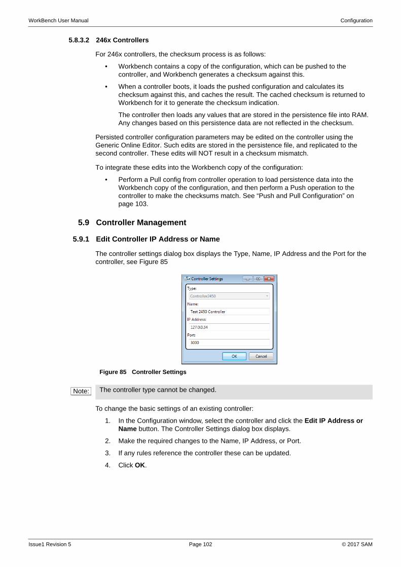
WorkBench User Manual Configuration
5.8.3.2 246x Controllers
For 246x controllers, the checksum process is as follows:
• Workbench contains a copy of the configuration, which can be pushed to the controller, and Workbench generates a checksum against this.
• When a controller boots, it loads the pushed configuration and calculates its checksum against this, and caches the result. The cached checksum is returned to Workbench for it to generate the checksum indication.
The controller then loads any values that are stored in the persistence file into RAM. Any changes based on this persistence data are not reflected in the checksum.
Persisted controller configuration parameters may be edited on the controller using the Generic Online Editor. Such edits are stored in the persistence file, and replicated to the second controller. These edits will NOT result in a checksum mismatch.
To integrate these edits into the Workbench copy of the configuration:
• Perform a Pull config from controller operation to load persistence data into the Workbench copy of the configuration, and then perform a Push operation to the controller to make the checksums match. See “Push and Pull Configuration” on page 103.
5.9 Controller Management
5.9.1 Edit Controller IP Address or Name
The controller settings dialog box displays the Type, Name, IP Address and the Port for the controller, see Figure 85
To change the basic settings of an existing controller:
1. In the Configuration window, select the controller and click the Edit IP Address or Name button. The Controller Settings dialog box displays.
2. Make the required changes to the Name, IP Address, or Port.
3. If any rules reference the controller these can be updated.
4. Click OK.
Figure 85 Controller Settings
Note: The controller type cannot be changed.
Issue1 Revision 5 Page 102 © 2017 SAM
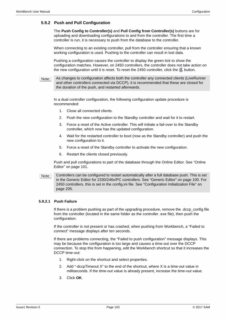
WorkBench User Manual Configuration
5.9.2 Push and Pull Configuration
The Push Config to Controller(s) and Pull Config from Controller(s) buttons are for uploading and downloading configurations to and from the controller. The first time a controller is run, it is necessary to push from the database to the controller.
When connecting to an existing controller, pull from the controller ensuring that a known working configuration is used. Pushing to the controller can result in lost data.
Pushing a configuration causes the controller to display the green tick to show the configuration matches. However, on 2450 controllers, the controller does not take action on the new configuration until it is reset. To reset the 2450 controller, click the button.
In a dual controller configuration, the following configuration update procedure is recommended:
1. Close all connected clients.
2. Push the new configuration to the Standby controller and wait for it to restart.
3. Force a reset of the Active controller. This will initiate a fail-over to the Standby controller, which now has the updated configuration.
4. Wait for the restarted controller to boot (now as the Standby controller) and push the new configuration to it.
5. Force a reset of the Standby controller to activate the new configuration.
6. Restart the clients closed previously.
Push and pull configurations to part of the database through the Online Editor. See “Online Editor” on page 101.
5.9.2.1 Push Failure
If there is a problem pushing as part of the upgrading procedure, remove the .dccp_config file from the controller (located in the same folder as the controller .exe file), then push the configuration.
If the controller is not present or has crashed, when pushing from Workbench, a “Failed to connect” message displays after ten seconds.
If there are problems connecting, the “Failed to push configuration” message displays. This may be because the configuration is too large and causes a time-out over the DCCP connection. To stop this from happening, edit the Workbench shortcut so that it increases the DCCP time-out:
1. Right-click on the shortcut and select properties.
2. Add “-dccpTimeout X” to the end of the shortcut, where X is a time-out value in milliseconds. If the time-out value is already present, increase the time-out value.
3. Click OK.
Note: As changes to configuration affects both the controller any connected clients (LiveRunner and other controllers connected via DCCP), it is recommended that these are closed for the duration of the push, and restarted afterwards.
Note: Controllers can be configured to restart automatically after a full database push. This is set in the Generic Editor for 2330/246x/PC controllers. See “Generic Editor” on page 100. For 2450 controllers, this is set in the config.ini file. See “Configuration Initialization File” on page 205.
Issue1 Revision 5 Page 103 © 2017 SAM
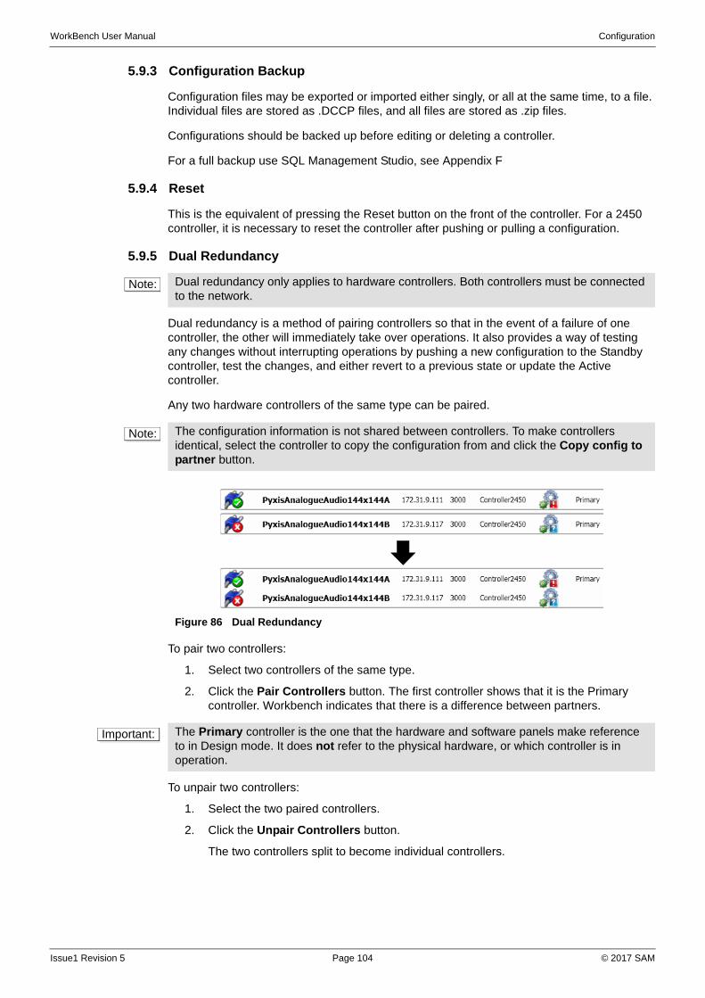
WorkBench User Manual Configuration
5.9.3 Configuration Backup
Configuration files may be exported or imported either singly, or all at the same time, to a file. Individual files are stored as .DCCP files, and all files are stored as .zip files.
Configurations should be backed up before editing or deleting a controller.
For a full backup use SQL Management Studio, see Appendix F
5.9.4 Reset
This is the equivalent of pressing the Reset button on the front of the controller. For a 2450 controller, it is necessary to reset the controller after pushing or pulling a configuration.
5.9.5 Dual Redundancy
Dual redundancy is a method of pairing controllers so that in the event of a failure of one controller, the other will immediately take over operations. It also provides a way of testing any changes without interrupting operations by pushing a new configuration to the Standby controller, test the changes, and either revert to a previous state or update the Active controller.
Any two hardware controllers of the same type can be paired.
To pair two controllers:
1. Select two controllers of the same type.
2. Click the Pair Controllers button. The first controller shows that it is the Primary controller. Workbench indicates that there is a difference between partners.
To unpair two controllers:
1. Select the two paired controllers.
2. Click the Unpair Controllers button.
The two controllers split to become individual controllers.
Note: Dual redundancy only applies to hardware controllers. Both controllers must be connected to the network.
Note: The configuration information is not shared between controllers. To make controllers identical, select the controller to copy the configuration from and click the Copy config to partner button.
Figure 86 Dual Redundancy
Important: The Primary controller is the one that the hardware and software panels make reference to in Design mode. It does not refer to the physical hardware, or which controller is in operation.
Issue1 Revision 5 Page 104 © 2017 SAM
WorkBench User Manual Configuration
5.9.5.1 Copy Config to Partner
This copies the configuration from the selected controller to the paired controller, the status shows that both controllers are synchronised. This is particularly useful when installing a replacement controller card, for example, to copy the current configuration to the new controller.
5.9.5.2 Swap Controllers
This swaps the Primary controller with the Secondary controller.
After swapping the controllers, push the configuration to the new Primary controller.
5.9.5.3 Auto-Changeover
Controllers can also be set to switch operation from the Active controller to the Standby controller in the event of a network failure.
For 2450 controllers, this feature is set using the Generic Editor. See “Generic Editor” on page 100.
1. Expand the Controller node.
2. Expand the Config2450 node.
3. Expand the Features node.
4. Edit the AutoChangeOverIfNoNetwork giving a time (in seconds), for which the network has failed before performing the changeover to the Standby controller.
A time of -1 disables this feature.
For 246x controllers, this feature is set using the Online Editor. See “Online Editor” on page 101.
1. Expand the Controller node.
2. Expand the ConfigurationItems node
3. Expand the MiscellaneousFeatures node.
4. Edit the AutoChangeOverIfNoNetwork giving a time (in seconds), for which the network has failed before performing the changeover to the Standby controller.
A time of -1 disables this feature.
5.9.6 Refresh
This refreshes the list view of the controllers.
Important: Swapping controllers loses the behavior for any hardware or software panels that references the Primary controller. Reconfigure the panels to reference the new Primary controller.
Note: The changeover occurs only if the Standby controller has a working network connection.
Note: The AutoChangeOverIfNoNetwork feature under the Features node has no effect.
Issue1 Revision 5 Page 105 © 2017 SAM
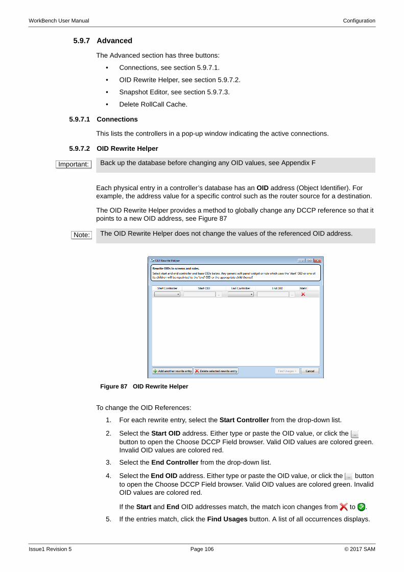
WorkBench User Manual Configuration
5.9.7 Advanced
The Advanced section has three buttons:
• Connections, see section 5.9.7.1.
• OID Rewrite Helper, see section 5.9.7.2.
• Snapshot Editor, see section 5.9.7.3.
• Delete RollCall Cache.
5.9.7.1 Connections
This lists the controllers in a pop-up window indicating the active connections.
5.9.7.2 OID Rewrite Helper
Each physical entry in a controller’s database has an OID address (Object Identifier). For example, the address value for a specific control such as the router source for a destination.
The OID Rewrite Helper provides a method to globally change any DCCP reference so that it points to a new OID address, see Figure 87
To change the OID References:
1. For each rewrite entry, select the Start Controller from the drop-down list.
2. Select the Start OID address. Either type or paste the OID value, or click the button to open the Choose DCCP Field browser. Valid OID values are colored green. Invalid OID values are colored red.
3. Select the End Controller from the drop-down list.
4. Select the End OID address. Either type or paste the OID value, or click the button to open the Choose DCCP Field browser. Valid OID values are colored green. Invalid OID values are colored red.
If the Start and End OID addresses match, the match icon changes from to .
5. If the entries match, click the Find Usages button. A list of all occurrences displays.
Important: Back up the database before changing any OID values, see Appendix F
Note: The OID Rewrite Helper does not change the values of the referenced OID address.
Figure 87 OID Rewrite Helper
Issue1 Revision 5 Page 106 © 2017 SAM
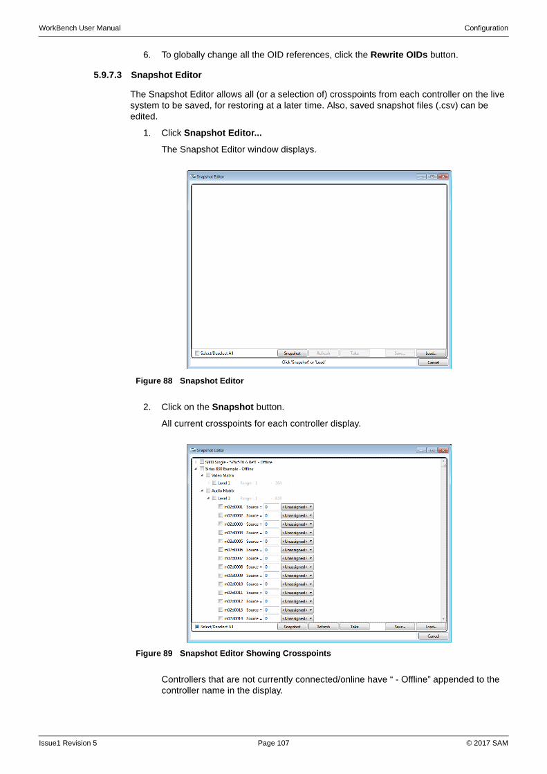
WorkBench User Manual Configuration
6. To globally change all the OID references, click the Rewrite OIDs button.
5.9.7.3 Snapshot Editor
The Snapshot Editor allows all (or a selection of) crosspoints from each controller on the live system to be saved, for restoring at a later time. Also, saved snapshot files (.csv) can be edited.
1. Click Snapshot Editor...
The Snapshot Editor window displays.
2. Click on the Snapshot button.
All current crosspoints for each controller display.
Controllers that are not currently connected/online have “ - Offline” appended to the controller name in the display.
Figure 88 Snapshot Editor
Figure 89 Snapshot Editor Showing Crosspoints
Issue1 Revision 5 Page 107 © 2017 SAM
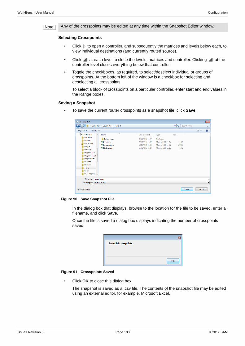
WorkBench User Manual Configuration
Selecting Crosspoints
• Click to open a controller, and subsequently the matrices and levels below each, to view individual destinations (and currently routed source).
• Click at each level to close the levels, matrices and controller. Clicking at the controller level closes everything below that controller.
• Toggle the checkboxes, as required, to select/deselect individual or groups of crosspoints. At the bottom left of the window is a checkbox for selecting and deselecting all crosspoints.
To select a block of crosspoints on a particular controller, enter start and end values in the Range boxes.
Saving a Snapshot
• To save the current router crosspoints as a snapshot file, click Save.
In the dialog box that displays, browse to the location for the file to be saved, enter a filename, and click Save.
Once the file is saved a dialog box displays indicating the number of crosspoints saved.
• Click OK to close this dialog box.
The snapshot is saved as a .csv file. The contents of the snapshot file may be edited using an external editor, for example, Microsoft Excel.
Note: Any of the crosspoints may be edited at any time within the Snapshot Editor window.
Figure 90 Save Snapshot File
Figure 91 Crosspoints Saved
Issue1 Revision 5 Page 108 © 2017 SAM
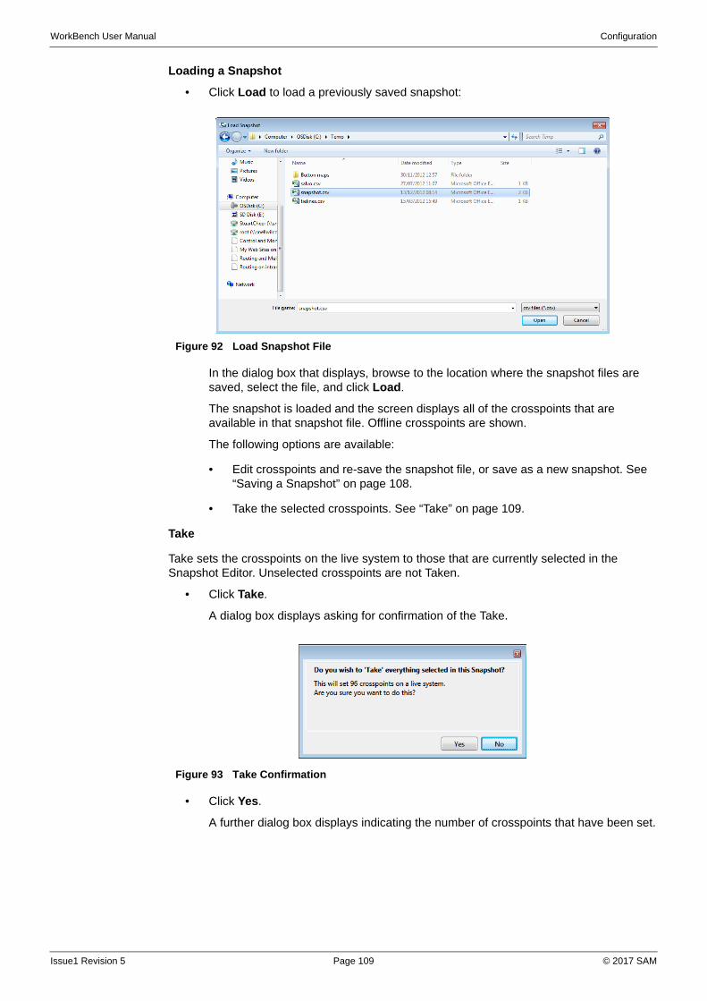
WorkBench User Manual Configuration
Loading a Snapshot
• Click Load to load a previously saved snapshot:
In the dialog box that displays, browse to the location where the snapshot files are saved, select the file, and click Load.
The snapshot is loaded and the screen displays all of the crosspoints that are available in that snapshot file. Offline crosspoints are shown.
The following options are available:
• Edit crosspoints and re-save the snapshot file, or save as a new snapshot. See “Saving a Snapshot” on page 108.
• Take the selected crosspoints. See “Take” on page 109.
Take
Take sets the crosspoints on the live system to those that are currently selected in the Snapshot Editor. Unselected crosspoints are not Taken.
• Click Take.
A dialog box displays asking for confirmation of the Take.
• Click Yes.
A further dialog box displays indicating the number of crosspoints that have been set.
Figure 92 Load Snapshot File
Figure 93 Take Confirmation
Issue1 Revision 5 Page 109 © 2017 SAM
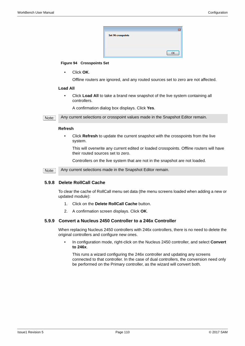
WorkBench User Manual Configuration
• Click OK.
Offline routers are ignored, and any routed sources set to zero are not affected.
Load All
• Click Load All to take a brand new snapshot of the live system containing all controllers.
A confirmation dialog box displays. Click Yes.
Refresh
• Click Refresh to update the current snapshot with the crosspoints from the live system.
This will overwrite any current edited or loaded crosspoints. Offline routers will have their routed sources set to zero.
Controllers on the live system that are not in the snapshot are not loaded.
5.9.8 Delete RollCall Cache
To clear the cache of RollCall menu set data (the menu screens loaded when adding a new or updated module):
1. Click on the Delete RollCall Cache button.
2. A confirmation screen displays. Click OK.
5.9.9 Convert a Nucleus 2450 Controller to a 246x Controller
When replacing Nucleus 2450 controllers with 246x controllers, there is no need to delete the original controllers and configure new ones.
• In configuration mode, right-click on the Nucleus 2450 controller, and select Convert to 246x.
This runs a wizard configuring the 246x controller and updating any screens connected to that controller. In the case of dual controllers, the conversion need only be performed on the Primary controller, as the wizard will convert both.
Figure 94 Crosspoints Set
Note: Any current selections or crosspoint values made in the Snapshot Editor remain.
Note: Any current selections made in the Snapshot Editor remain.
Issue1 Revision 5 Page 110 © 2017 SAM

WorkBench User Manual Configuration
5.9.10 Upgrading
When Workbench is upgraded, it is recommended that PC controllers also be upgraded.
5.9.10.1 PC-based Controllers
1. Copy the ‘CentraController.exe’ file and overwrite the existing controllers.
2. Delete the ‘CentraController.dccp_config’ files that are in the controller’s folders (the config files are unlikely to work across versions and may even crash the controllers).
3. Restart the controllers.
4. Push their configurations, see section 5.9.2.
Issue1 Revision 5 Page 111 © 2017 SAM

WorkBench User Manual Configuration
Issue1 Revision 5 Page 112 © 2017 SAM
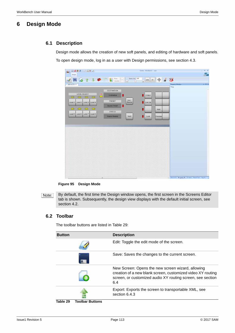
WorkBench User Manual Design Mode
6 Design Mode
6.1 Description
Design mode allows the creation of new soft panels, and editing of hardware and soft panels.
To open design mode, log in as a user with Design permissions, see section 4.3.
6.2 Toolbar
The toolbar buttons are listed in Table 29:
Figure 95 Design Mode
Note: By default, the first time the Design window opens, the first screen in the Screens Editor tab is shown. Subsequently, the design view displays with the default initial screen, see section 4.2.
Button Description
Edit: Toggle the edit mode of the screen.
Save: Saves the changes to the current screen.
New Screen: Opens the new screen wizard, allowing creation of a new blank screen, customized video XY routing screen, or customized audio XY routing screen, see section 6.4
Export: Exports the screen to transportable XML, see section 6.4.3
Table 29 Toolbar Buttons
Issue1 Revision 5 Page 113 © 2017 SAM
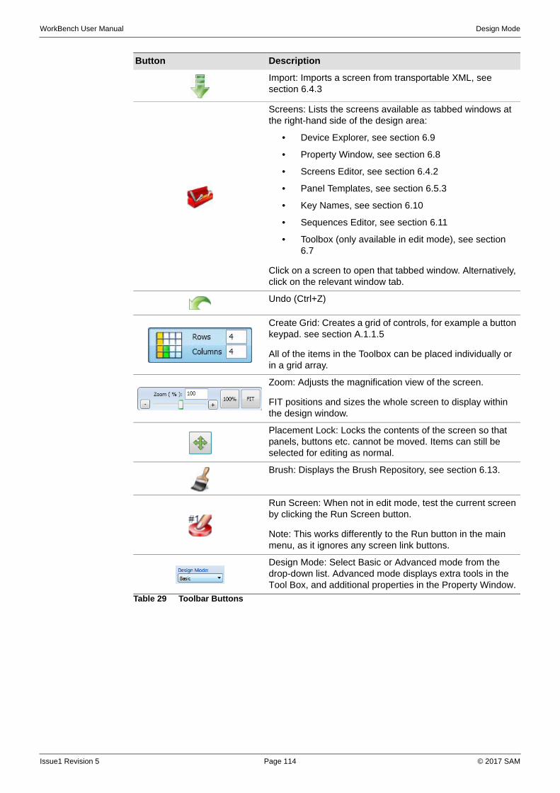
WorkBench User Manual Design Mode
Import: Imports a screen from transportable XML, see section 6.4.3
Screens: Lists the screens available as tabbed windows at the right-hand side of the design area:
• Device Explorer, see section 6.9
• Property Window, see section 6.8
• Screens Editor, see section 6.4.2
• Panel Templates, see section 6.5.3
• Key Names, see section 6.10
• Sequences Editor, see section 6.11
• Toolbox (only available in edit mode), see section 6.7
Click on a screen to open that tabbed window. Alternatively, click on the relevant window tab.
Undo (Ctrl+Z)
Create Grid: Creates a grid of controls, for example a button keypad. see section A.1.1.5
All of the items in the Toolbox can be placed individually or in a grid array.
Zoom: Adjusts the magnification view of the screen.
FIT positions and sizes the whole screen to display within the design window.
Placement Lock: Locks the contents of the screen so that panels, buttons etc. cannot be moved. Items can still be selected for editing as normal.
Brush: Displays the Brush Repository, see section 6.13.
Run Screen: When not in edit mode, test the current screen by clicking the Run Screen button.
Note: This works differently to the Run button in the main menu, as it ignores any screen link buttons.
Design Mode: Select Basic or Advanced mode from the drop-down list. Advanced mode displays extra tools in the Tool Box, and additional properties in the Property Window.
Button Description
Table 29 Toolbar Buttons
Issue1 Revision 5 Page 114 © 2017 SAM
WorkBench User Manual Design Mode
6.3 Menu
When in edit mode, a right-clicking the main design area of the displays an editing menu:
6.4 Screens
A screen is a container for one or more panels. Each screen must have at least one Soft Panel or Hardware Panel, see section 6.5.
The Worked Examples provide guidelines. See Appendix A
To create a new screen, select one of the following:
• Create a new blank screen, and add panels and controls from the toolbar, see section 6.4.1.
• Select a panel from the Screens Editor tab, make a clone of it, and configure the new version as required, see section 6.4.2.
• Create a new Hardware Panel through the Add Hardware Panels Wizard. The wizard has the advantage that many of the parameters are configured for the controller, see section 5.6.1.
• Import an existing screen and configure it as required, see section 6.4.3.
• Screens can be grouped together in folders. Right-click on the Screens Folder, and click on the New Folder from the menu. Click on the folder name to rename it.
Delete Deletes the current selection
Cut Cuts the current selection
Copy Copies the current selection
Paste Pastes the last item cut or copied into the current location
Paste Special... Paste all widgets into the current Group
Key Sequences Opens the Key Sequences Editor. See “Key Sequences” on page 128.
Maximise Panel Enlarge the panel to the full size of the Screen. See “Screens” on page 115.
Auto Edit Opens the Auto Edit dialog box. See “Auto Edit” on page 130.
Add Tab Page Adds a new tab (when a tab is selected)
Remove Tab Page Removes the current tab (when a tab is selected)
Create Template Add a new panel template (when a panel is selected)
Send to Back Move the current selection to the back of the screen
Send Backwards Move the current selection one step backwards to behind the next most forward item
Bring to Front Move the current selection to the front of the screen
Bring Forwards Move the current selection one step forwards to in front of the next most forward item
Properties Opens the Property window for the current selection
Screen Properties Opens the Property window for the Screen
Group Properties Opens the Property window for the Group
Note: The screens listed in the Screens Editor tab are part of the “Example Resources” option of the Workbench installation.
Issue1 Revision 5 Page 115 © 2017 SAM

WorkBench User Manual Design Mode
6.4.1 Create a New Blank Screen
To create a new blank screen:
1. At the bottom-right of the window, select the Screens Editor tab, see section 6.4.2.
2. Either on the Screens Editor tab click the Add button, or on the toolbar click the button.
The New Screen wizard displays.
3. Type a name for the new screen.
4. From the drop-down list select the type of screen to create:
• Blank—build up a screen with as many panels as required for any number of different tasks are necessary.
• Basic Routing—a video XY routing panel template that can be edited, as required.
• Audio Track Routing—an audio XY routing panel template that can be edited, as required.
If a Blank screen is selected, click Finish. The screen displays, and is ready for editing.
If a Video or Audio screen is selected, click Next.
5. Select a screen size and select a color theme from the drop-down lists.
6. Click Next.
7. Select a controller and matrix from the drop-down lists.
8. Click Finish. The screen displays, and can be edited, as required.
Note: To open any screen in the list, double-click on the thumbnail. Only one screen can open at a time.
Issue1 Revision 5 Page 116 © 2017 SAM
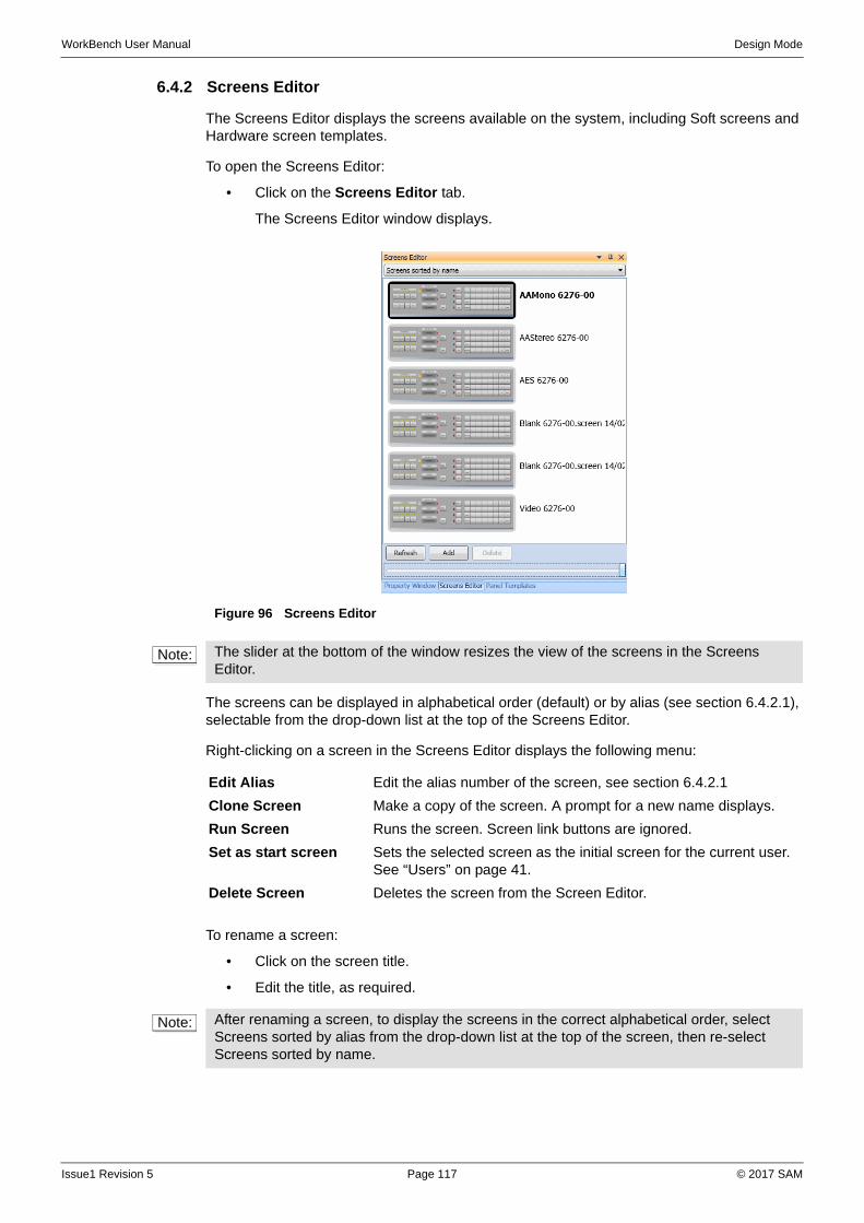
WorkBench User Manual Design Mode
6.4.2 Screens Editor
The Screens Editor displays the screens available on the system, including Soft screens and Hardware screen templates.
To open the Screens Editor:
• Click on the Screens Editor tab.
The Screens Editor window displays.
The screens can be displayed in alphabetical order (default) or by alias (see section 6.4.2.1), selectable from the drop-down list at the top of the Screens Editor.
Right-clicking on a screen in the Screens Editor displays the following menu:
.
To rename a screen:
• Click on the screen title.
• Edit the title, as required.
Figure 96 Screens Editor
Note: The slider at the bottom of the window resizes the view of the screens in the Screens Editor.
Edit Alias Edit the alias number of the screen, see section 6.4.2.1
Clone Screen Make a copy of the screen. A prompt for a new name displays.
Run Screen Runs the screen. Screen link buttons are ignored.
Set as start screen Sets the selected screen as the initial screen for the current user. See “Users” on page 41.
Delete Screen Deletes the screen from the Screen Editor.
Note: After renaming a screen, to display the screens in the correct alphabetical order, select Screens sorted by alias from the drop-down list at the top of the screen, then re-select Screens sorted by name.
Issue1 Revision 5 Page 117 © 2017 SAM
WorkBench User Manual Design Mode
6.4.2.1 Screen Alias
The screen alias is a number attributed to a screen to allow the screen to be referenced by that number. This is particularly useful when a screen is linked by another screen. If the alias number is used then any subsequent changes to the screen name will not inadvertently break the link between the screens.
By default all screens have an alias of zero; no alias. A zero alias is not indicated on the display.
To add an alias:
1. Right-click on a screen in the Screens Editor, and click Edit Alias.
2. Enter an alias number and click OK.
The alias number displays under the screen name in the Screens Editor.
6.4.3 Screen Templates
Several screen templates are included with Workbench. By default, panel templates are located in the Workbench installation folder, under:
...\Workbench\Screens\Hardware Panels
...\Workbench\Screens\Vistek
Screens are also made available to customers who have purchased SAM products such as hardware control panels and modular screens. These screen templates can be imported to Workbench, greatly reducing the amount of time required to build screens. Screens can also be found through the SAM Web site.
To import a screen template:
1. From the toolbar, click the button.
2. In the dialog box that displays, navigate to the template file.
3. Click Open.
If the screen is to be assigned to a different system, assign the relevant Group. See “Groups” on page 121.
To export a screen template:
1. From the toolbar, click the button.
2. In the dialog box that displays, select a location for the file to be saved, and change the name of the file if required.
3. Click Save.
Note: Backup and restore screens from Administration | Data Management, see section 4.7.
Issue1 Revision 5 Page 118 © 2017 SAM
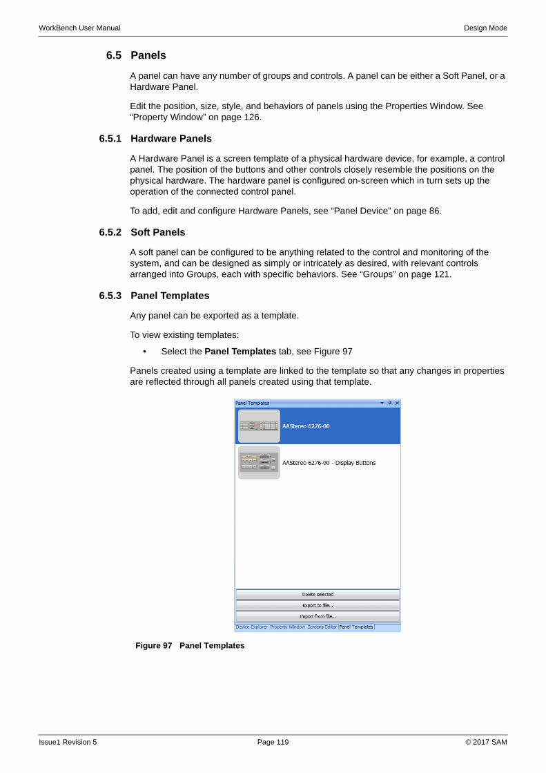
WorkBench User Manual Design Mode
6.5 Panels
A panel can have any number of groups and controls. A panel can be either a Soft Panel, or a Hardware Panel.
Edit the position, size, style, and behaviors of panels using the Properties Window. See “Property Window” on page 126.
6.5.1 Hardware Panels
A Hardware Panel is a screen template of a physical hardware device, for example, a control panel. The position of the buttons and other controls closely resemble the positions on the physical hardware. The hardware panel is configured on-screen which in turn sets up the operation of the connected control panel.
To add, edit and configure Hardware Panels, see “Panel Device” on page 86.
6.5.2 Soft Panels
A soft panel can be configured to be anything related to the control and monitoring of the system, and can be designed as simply or intricately as desired, with relevant controls arranged into Groups, each with specific behaviors. See “Groups” on page 121.
6.5.3 Panel Templates
Any panel can be exported as a template.
To view existing templates:
• Select the Panel Templates tab, see Figure 97
Panels created using a template are linked to the template so that any changes in properties are reflected through all panels created using that template.
Figure 97 Panel Templates
Issue1 Revision 5 Page 119 © 2017 SAM

WorkBench User Manual Design Mode
To create a new panel template:
1. Open the required panel from the Screens Editor tab.
2. Click the button to edit the panel. The Toolbox displays at the bottom of the window.
3. Right-click on the panel and select Create Template. The panel is added to the Panel Templates tab, with a default name of New Template.
4. Click on the Panel Templates tab.
5. Click on the new panel template title, and rename the panel template.
6.5.3.1 Use Panel Templates
To use a panel template:
• Double-click on the panel template from the list and click onto the screen. Repeat the process to add further panels on the screen.
Any number of panel templates may be added to a screen.
Changing a property of the panel causes all the panels linked to the template to change their property at the same time. For example, changing the color of a button background on a panel causes the same button background to change on all panels.
Any changes made to the panels are reflected back to the template, and the template is updated at the same time.
The properties of a panel can be changed without changing the template. See “Override Panels” on page 120.
6.5.3.2 Override Panels
A panel created from the panel template can be edited without affecting the template, by overriding it to change the properties required.
When in override mode, it is not possible to make changes to other panels. Also, it is not possible to add or remove groups, tabs or controls on the selected panel, in override mode.
To override a panel:
• Right-click on the panel, and from the menu click on Override Panel.
Any changes made during the override are not reflected on the other panels, nor is the template updated.
To return to editing all panels:
• Right-click on the panel in override mode, and from the menu click on Override Panel.
The panel is no longer in override mode and any editing of properties affects all panels.
6.5.3.3 Detach a Panel
A panel can be detached from the template, so that any further changes to the template do not affect the panel, or vice versa.
Note: Changing a property on a panel in override mode affects only that particular property, and other properties remain as per the template. For example, changing a button color only in override mode, then changing the size of that button on the template, results in the button with the override on the color still changing size accordingly with the template.
Note: It is not possible to override the Behavior property of a group or control, or the Group property of a control.
Issue1 Revision 5 Page 120 © 2017 SAM

WorkBench User Manual Design Mode
To detach a panel:
• Right-click on a panel, and from the menu click on Detach Panel.
6.6 Groups
The group properties determine the behavior of all the controls within the group, and are specific to the device type or piece of equipment that the controls act upon. For example, in an alarm group, only the control behaviors appropriate for alarms are available.
Each screen can have numerous groups, and each group can have a different behavior type. Table 31 lists the available groups:
Figure 98 Group Tabs
Icon Description
Adds a new group
Edit group name
Open group properties
Select all controls in group
Delete the current group
Table 30 Group Buttons
Group Name Description
Alarm Allows the alarms to trigger button states, and log to the screen. For example, setting alarms, acknowledgements and automatic resets.
Audio Path Allows monitoring of the routes that individual audio channels take.
Audio Processing For defining audio processing screens.
Audio Router XY Group
Controls for designing audio routing screens allowing groups of audio, for example, stereo pairs, to be routed and embedded onto a video stream for output.
Audio Router XY Track Controls for designing audio routing screens allowing audio tracks to be routed and embedded onto a video stream on output.
Device Chain Not for general use – used with mimic.
Generic Allows control or status monitoring from any part of any device through the unique OID identifier. For use with drag and drop design.
Note: For generic group behaviors it is possible to assign a property that may be inappropriate for a control.
Generic Dial Up Allows for large sized routers to be controlled by a single panel.
Hardware Panel BPX For configuring BPX hardware panels. Using the template in the Screen Editor is recommended.
Hardware Panel MultiBus
For configuring 6277 hardware panels. Using the template in the Screen Editor is recommended.
Table 31 Group Behaviors
Issue1 Revision 5 Page 121 © 2017 SAM

WorkBench User Manual Design Mode
The Group properties determine the behavior of the controls within the group. Add controls from the Toolbox to the Group, see “Toolbox” on page 122.
For details of the behaviors that can be allocated to each design control, see Appendix E
6.7 Toolbox
The toolbox has groups of controls, each of which can be toggled open or closed by clicking on the Group Heading. Figure 99
The Toolbox displays at the bottom of the screen when in edit mode. The available list of behaviors on a control depends on the type of controller selected in the group, and the behavior for the group it is in. For example, a button can be a destination for a router, or a play button for video server.
Edit the position, size, style, and behaviors of the tools using the Properties Window. See “Property Window” on page 126.
Hardware Panel XY For configuring XY hardware panels. Using the template in the Screen Editor is recommended.
Hardware Panel XY6276
For configuring 6276 hardware panels. Using the template in the Screen Editor is recommended.
Mimic Allows for mimic diagrams to work, requires system architecture configuration, see section 6.7.7.
Multi Bus Allows selection of source then destination routing to single router (normal configuration is to set a destination and then source).
Multi Matrix BPX Allows for selection of routes across tie-lines.
Multi Matrix Multi Bus Allows selection of source then destination across tie-lines.
Multi Matrix XY Allows for destination then source selection across tie-lines.
MultiViewer Device Screen recalls and pushing.
Passive (default) Used for text labels and other graphics when no other action is required.
Playout Device Required for VTR / server control, play list display.
Router BPX Allows selection of routes as a grid for single button per crosspoint to single router.
Router Dial Up Allows for keypad dial-up for routing functions, source and destination keypads.
Router XY Allows for destination then source selection on a single router.
Source Queue For use with reverse mimic chain. Not for general use.
Tag Name Editing Allows run mode editing of names without altering the configuration.
Group Name Description
Table 31 Group Behaviors
Figure 99 Toolbox Tabs and Controls
Group Headings
Issue1 Revision 5 Page 122 © 2017 SAM
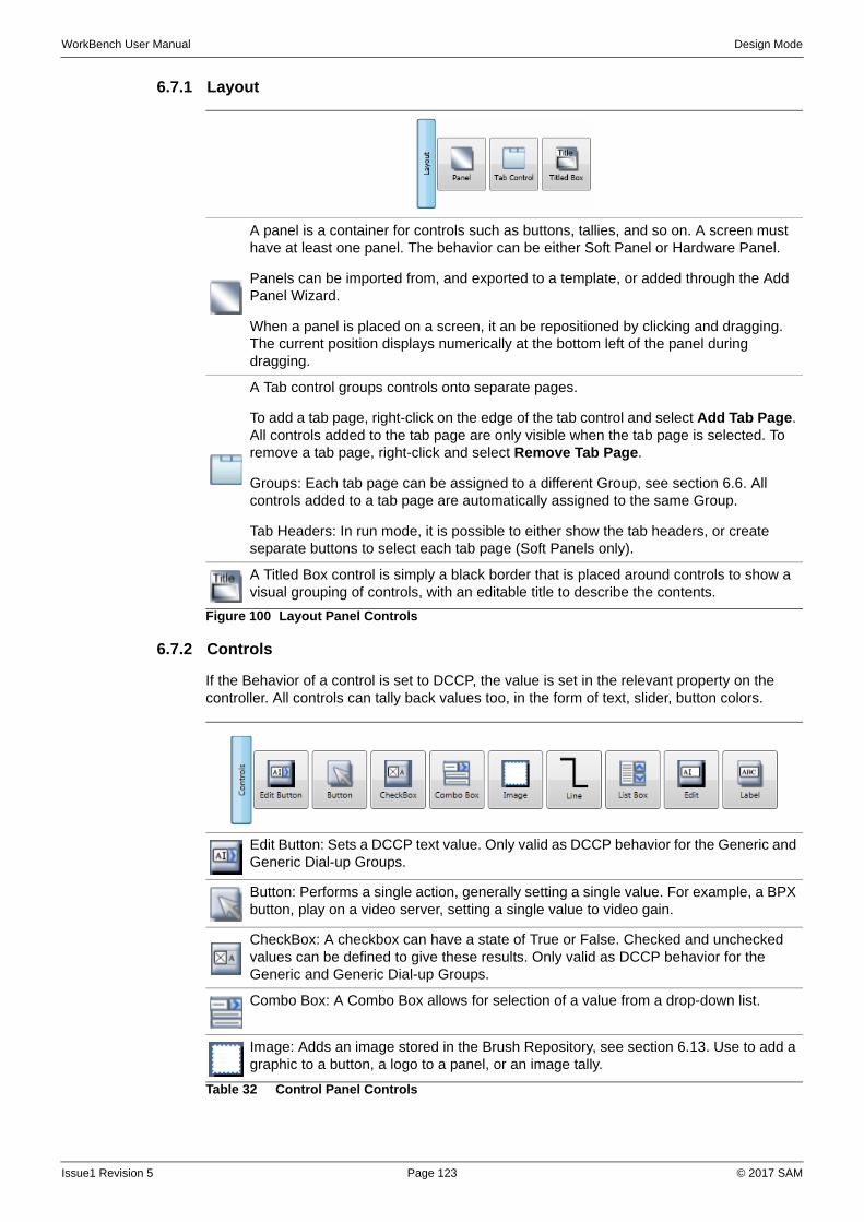
WorkBench User Manual Design Mode
6.7.1 Layout
6.7.2 Controls
If the Behavior of a control is set to DCCP, the value is set in the relevant property on the controller. All controls can tally back values too, in the form of text, slider, button colors.
A panel is a container for controls such as buttons, tallies, and so on. A screen must have at least one panel. The behavior can be either Soft Panel or Hardware Panel.
Panels can be imported from, and exported to a template, or added through the Add Panel Wizard.
When a panel is placed on a screen, it an be repositioned by clicking and dragging. The current position displays numerically at the bottom left of the panel during dragging.
A Tab control groups controls onto separate pages.
To add a tab page, right-click on the edge of the tab control and select Add Tab Page. All controls added to the tab page are only visible when the tab page is selected. To remove a tab page, right-click and select Remove Tab Page.
Groups: Each tab page can be assigned to a different Group, see section 6.6. All controls added to a tab page are automatically assigned to the same Group.
Tab Headers: In run mode, it is possible to either show the tab headers, or create separate buttons to select each tab page (Soft Panels only).
A Titled Box control is simply a black border that is placed around controls to show a visual grouping of controls, with an editable title to describe the contents.
Figure 100 Layout Panel Controls
Edit Button: Sets a DCCP text value. Only valid as DCCP behavior for the Generic and Generic Dial-up Groups.
Button: Performs a single action, generally setting a single value. For example, a BPX button, play on a video server, setting a single value to video gain.
CheckBox: A checkbox can have a state of True or False. Checked and unchecked values can be defined to give these results. Only valid as DCCP behavior for the Generic and Generic Dial-up Groups.
Combo Box: A Combo Box allows for selection of a value from a drop-down list.
Image: Adds an image stored in the Brush Repository, see section 6.13. Use to add a graphic to a button, a logo to a panel, or an image tally.
Table 32 Control Panel Controls
Issue1 Revision 5 Page 123 © 2017 SAM
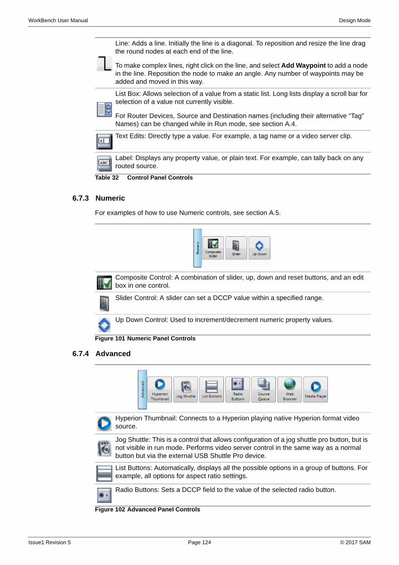
WorkBench User Manual Design Mode
6.7.3 Numeric
For examples of how to use Numeric controls, see section A.5.
6.7.4 Advanced
Line: Adds a line. Initially the line is a diagonal. To reposition and resize the line drag the round nodes at each end of the line.
To make complex lines, right click on the line, and select Add Waypoint to add a node in the line. Reposition the node to make an angle. Any number of waypoints may be added and moved in this way.
List Box: Allows selection of a value from a static list. Long lists display a scroll bar for selection of a value not currently visible.
For Router Devices, Source and Destination names (including their alternative “Tag” Names) can be changed while in Run mode, see section A.4.
Text Edits: Directly type a value. For example, a tag name or a video server clip.
Label: Displays any property value, or plain text. For example, can tally back on any routed source.
Table 32 Control Panel Controls
Composite Control: A combination of slider, up, down and reset buttons, and an edit box in one control.
Slider Control: A slider can set a DCCP value within a specified range.
Up Down Control: Used to increment/decrement numeric property values.
Figure 101 Numeric Panel Controls
Hyperion Thumbnail: Connects to a Hyperion playing native Hyperion format video source.
Jog Shuttle: This is a control that allows configuration of a jog shuttle pro button, but is not visible in run mode. Performs video server control in the same way as a normal button but via the external USB Shuttle Pro device.
List Buttons: Automatically, displays all the possible options in a group of buttons. For example, all options for aspect ratio settings.
Radio Buttons: Sets a DCCP field to the value of the selected radio button.
Figure 102 Advanced Panel Controls
Issue1 Revision 5 Page 124 © 2017 SAM
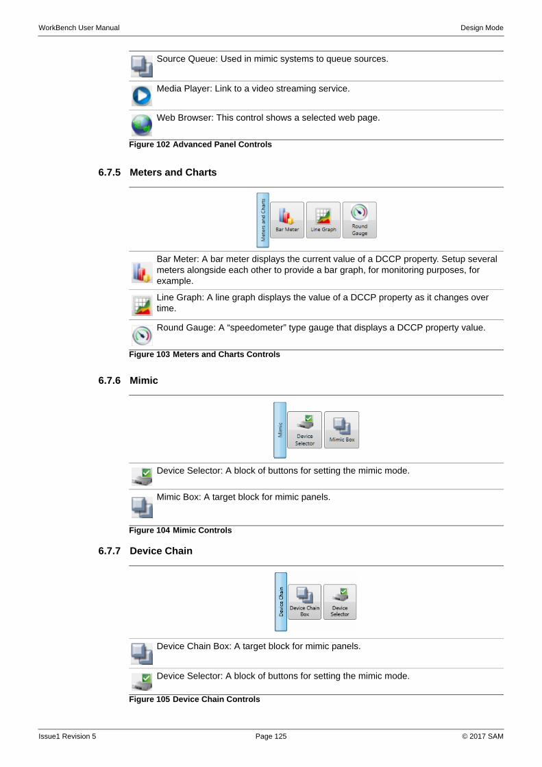
WorkBench User Manual Design Mode
6.7.5 Meters and Charts
6.7.6 Mimic
6.7.7 Device Chain
Source Queue: Used in mimic systems to queue sources.
Media Player: Link to a video streaming service.
Web Browser: This control shows a selected web page.
Figure 102 Advanced Panel Controls
Bar Meter: A bar meter displays the current value of a DCCP property. Setup several meters alongside each other to provide a bar graph, for monitoring purposes, for example.
Line Graph: A line graph displays the value of a DCCP property as it changes over time.
Round Gauge: A “speedometer” type gauge that displays a DCCP property value.
Figure 103 Meters and Charts Controls
Device Selector: A block of buttons for setting the mimic mode.
Mimic Box: A target block for mimic panels.
Figure 104 Mimic Controls
Device Chain Box: A target block for mimic panels.
Device Selector: A block of buttons for setting the mimic mode.
Figure 105 Device Chain Controls
Issue1 Revision 5 Page 125 © 2017 SAM
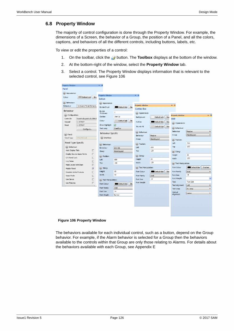
WorkBench User Manual Design Mode
6.8 Property Window
The majority of control configuration is done through the Property Window. For example, the dimensions of a Screen, the behavior of a Group, the position of a Panel, and all the colors, captions, and behaviors of all the different controls, including buttons, labels, etc.
To view or edit the properties of a control:
1. On the toolbar, click the button. The Toolbox displays at the bottom of the window.
2. At the bottom-right of the window, select the Property Window tab.
3. Select a control. The Property Window displays information that is relevant to the selected control, see Figure 106
The behaviors available for each individual control, such as a button, depend on the Group behavior. For example, if the Alarm behavior is selected for a Group then the behaviors available to the controls within that Group are only those relating to Alarms. For details about the behaviors available with each Group, see Appendix E
Figure 106 Property Window
Issue1 Revision 5 Page 126 © 2017 SAM
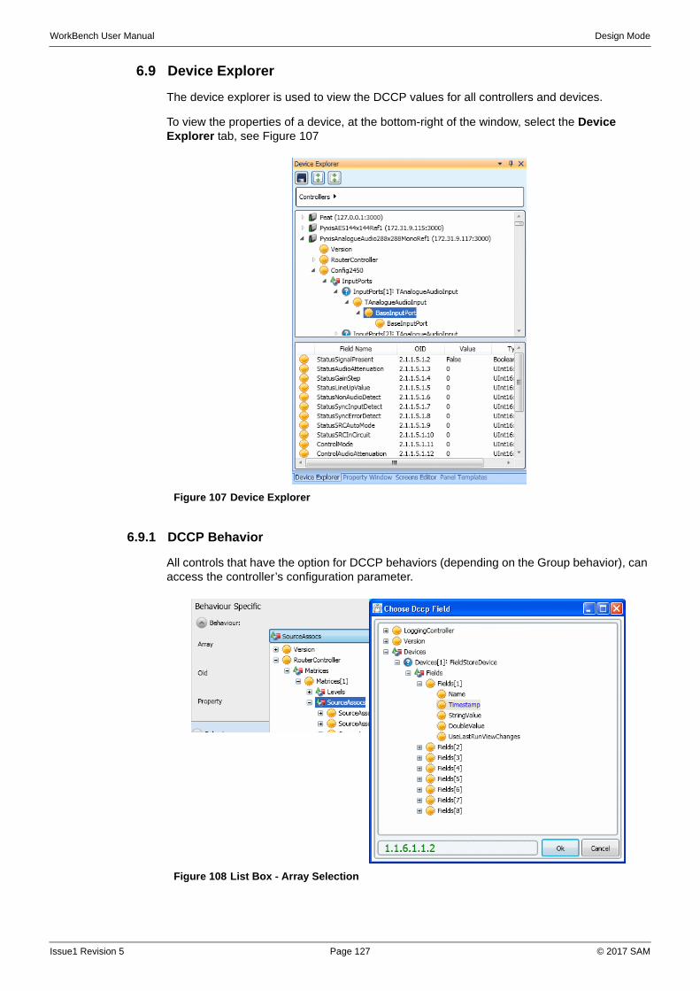
WorkBench User Manual Design Mode
6.9 Device Explorer
The device explorer is used to view the DCCP values for all controllers and devices.
To view the properties of a device, at the bottom-right of the window, select the Device Explorer tab, see Figure 107
6.9.1 DCCP Behavior
All controls that have the option for DCCP behaviors (depending on the Group behavior), can access the controller’s configuration parameter.
Figure 107 Device Explorer
Figure 108 List Box - Array Selection
Issue1 Revision 5 Page 127 © 2017 SAM
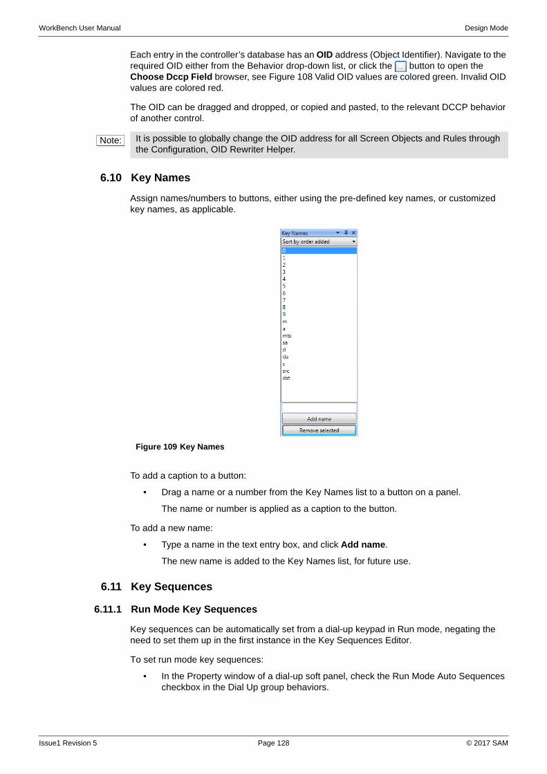
WorkBench User Manual Design Mode
Each entry in the controller’s database has an OID address (Object Identifier). Navigate to the required OID either from the Behavior drop-down list, or click the button to open the Choose Dccp Field browser, see Figure 108 Valid OID values are colored green. Invalid OID values are colored red.
The OID can be dragged and dropped, or copied and pasted, to the relevant DCCP behavior of another control.
6.10 Key Names
Assign names/numbers to buttons, either using the pre-defined key names, or customized key names, as applicable.
To add a caption to a button:
• Drag a name or a number from the Key Names list to a button on a panel.
The name or number is applied as a caption to the button.
To add a new name:
• Type a name in the text entry box, and click Add name.
The new name is added to the Key Names list, for future use.
6.11 Key Sequences
6.11.1 Run Mode Key Sequences
Key sequences can be automatically set from a dial-up keypad in Run mode, negating the need to set them up in the first instance in the Key Sequences Editor.
To set run mode key sequences:
• In the Property window of a dial-up soft panel, check the Run Mode Auto Sequences checkbox in the Dial Up group behaviors.
Note: It is possible to globally change the OID address for all Screen Objects and Rules through the Configuration, OID Rewriter Helper.
Figure 109 Key Names
Issue1 Revision 5 Page 128 © 2017 SAM
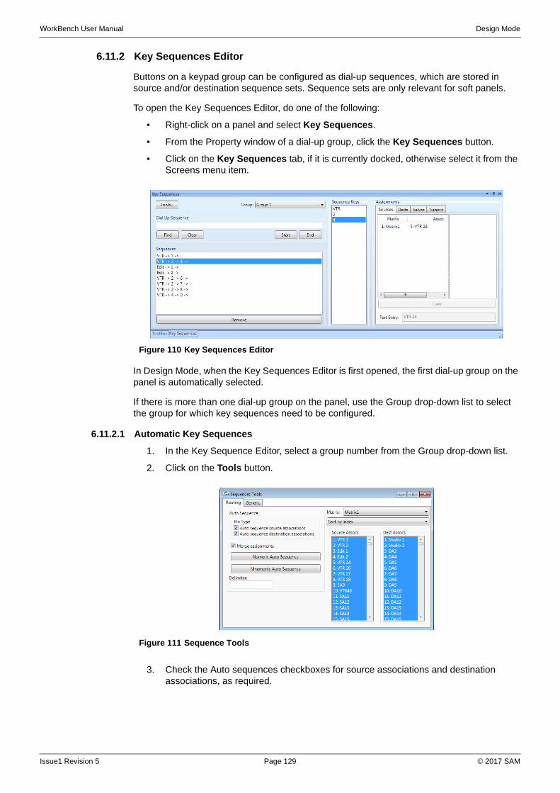
WorkBench User Manual Design Mode
6.11.2 Key Sequences Editor
Buttons on a keypad group can be configured as dial-up sequences, which are stored in source and/or destination sequence sets. Sequence sets are only relevant for soft panels.
To open the Key Sequences Editor, do one of the following:
• Right-click on a panel and select Key Sequences.
• From the Property window of a dial-up group, click the Key Sequences button.
• Click on the Key Sequences tab, if it is currently docked, otherwise select it from the Screens menu item.
In Design Mode, when the Key Sequences Editor is first opened, the first dial-up group on the panel is automatically selected.
If there is more than one dial-up group on the panel, use the Group drop-down list to select the group for which key sequences need to be configured.
6.11.2.1 Automatic Key Sequences
1. In the Key Sequence Editor, select a group number from the Group drop-down list.
2. Click on the Tools button.
3. Check the Auto sequences checkboxes for source associations and destination associations, as required.
Figure 110 Key Sequences Editor
Figure 111 Sequence Tools
Issue1 Revision 5 Page 129 © 2017 SAM
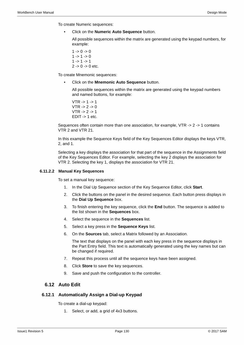
WorkBench User Manual Design Mode
To create Numeric sequences:
• Click on the Numeric Auto Sequence button.
All possible sequences within the matrix are generated using the keypad numbers, for example:
1 -> 0 -> 01 -> 1 -> 01 -> 1 -> 12 -> 0 -> 0 etc.
To create Mnemonic sequences:
• Click on the Mnemonic Auto Sequence button.
All possible sequences within the matrix are generated using the keypad numbers and named buttons, for example:
VTR -> 1 -> 1VTR -> 2 -> 0VTR -> 2 -> 1 EDIT -> 1 etc.
Sequences often contain more than one association, for example, VTR -> 2 -> 1 contains VTR 2 and VTR 21.
In this example the Sequence Keys field of the Key Sequences Editor displays the keys VTR, 2, and 1.
Selecting a key displays the association for that part of the sequence in the Assignments field of the Key Sequences Editor. For example, selecting the key 2 displays the association for VTR 2. Selecting the key 1, displays the association for VTR 21.
6.11.2.2 Manual Key Sequences
To set a manual key sequence:
1. In the Dial Up Sequence section of the Key Sequence Editor, click Start.
2. Click the buttons on the panel in the desired sequence. Each button press displays in the Dial Up Sequence box.
3. To finish entering the key sequence, click the End button. The sequence is added to the list shown in the Sequences box.
4. Select the sequence in the Sequences list.
5. Select a key press in the Sequence Keys list.
6. On the Sources tab, select a Matrix followed by an Association.
The text that displays on the panel with each key press in the sequence displays in the Part Entry field. This text is automatically generated using the key names but can be changed if required.
7. Repeat this process until all the sequence keys have been assigned.
8. Click Store to save the key sequences.
9. Save and push the configuration to the controller.
6.12 Auto Edit
6.12.1 Automatically Assign a Dial-up Keypad
To create a dial-up keypad:
1. Select, or add, a grid of 4x3 buttons.
Issue1 Revision 5 Page 130 © 2017 SAM
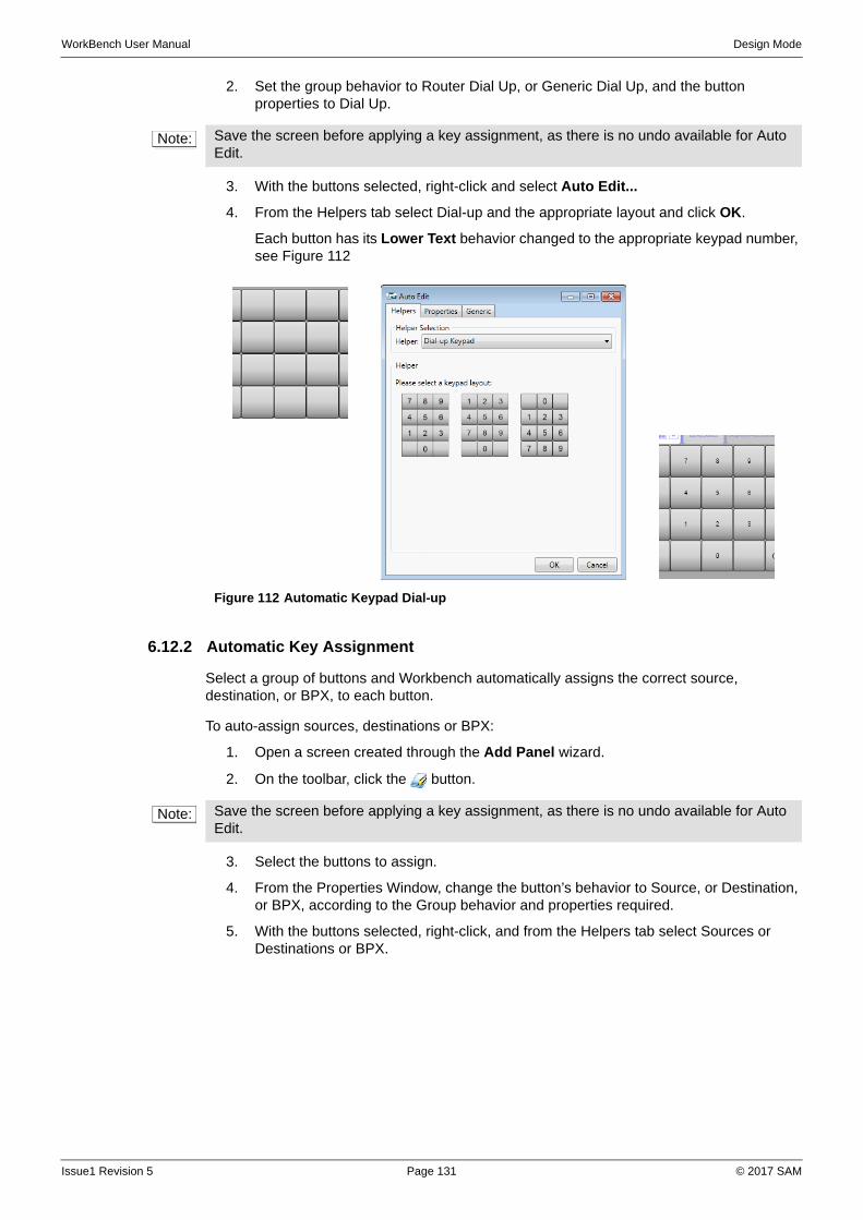
WorkBench User Manual Design Mode
2. Set the group behavior to Router Dial Up, or Generic Dial Up, and the button properties to Dial Up.
3. With the buttons selected, right-click and select Auto Edit...
4. From the Helpers tab select Dial-up and the appropriate layout and click OK.
Each button has its Lower Text behavior changed to the appropriate keypad number, see Figure 112
6.12.2 Automatic Key Assignment
Select a group of buttons and Workbench automatically assigns the correct source, destination, or BPX, to each button.
To auto-assign sources, destinations or BPX:
1. Open a screen created through the Add Panel wizard.
2. On the toolbar, click the button.
3. Select the buttons to assign.
4. From the Properties Window, change the button’s behavior to Source, or Destination, or BPX, according to the Group behavior and properties required.
5. With the buttons selected, right-click, and from the Helpers tab select Sources or Destinations or BPX.
Note: Save the screen before applying a key assignment, as there is no undo available for Auto Edit.
Figure 112 Automatic Keypad Dial-up
Note: Save the screen before applying a key assignment, as there is no undo available for Auto Edit.
Issue1 Revision 5 Page 131 © 2017 SAM
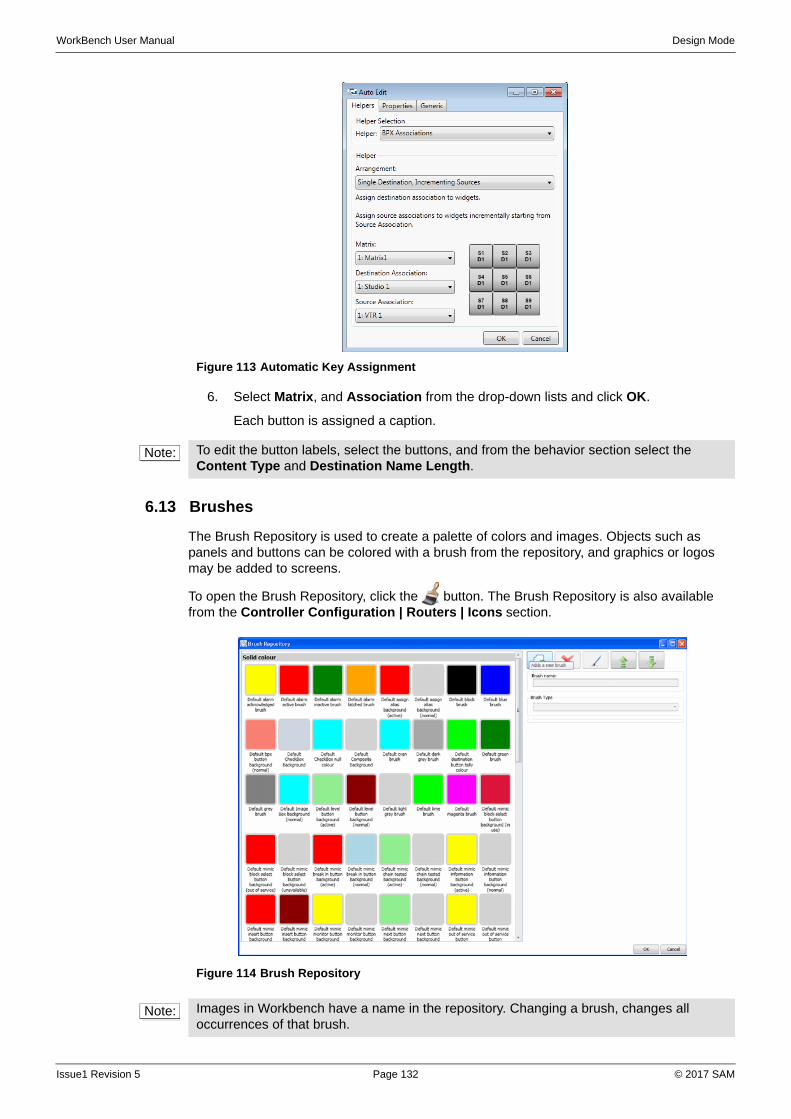
WorkBench User Manual Design Mode
6. Select Matrix, and Association from the drop-down lists and click OK.
Each button is assigned a caption.
6.13 Brushes
The Brush Repository is used to create a palette of colors and images. Objects such as panels and buttons can be colored with a brush from the repository, and graphics or logos may be added to screens.
To open the Brush Repository, click the button. The Brush Repository is also available from the Controller Configuration | Routers | Icons section.
Figure 113 Automatic Key Assignment
Note: To edit the button labels, select the buttons, and from the behavior section select the Content Type and Destination Name Length.
Figure 114 Brush Repository
Note: Images in Workbench have a name in the repository. Changing a brush, changes all occurrences of that brush.
Issue1 Revision 5 Page 132 © 2017 SAM
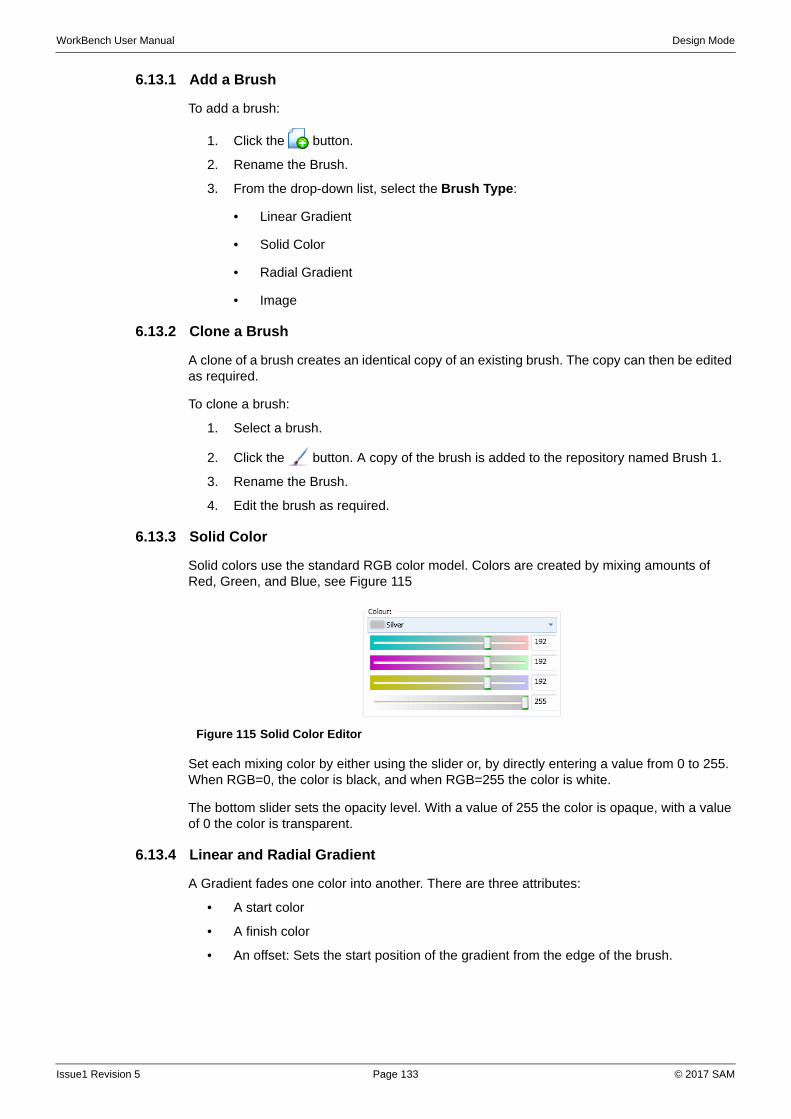
WorkBench User Manual Design Mode
6.13.1 Add a Brush
To add a brush:
1. Click the button.
2. Rename the Brush.
3. From the drop-down list, select the Brush Type:
• Linear Gradient
• Solid Color
• Radial Gradient
• Image
6.13.2 Clone a Brush
A clone of a brush creates an identical copy of an existing brush. The copy can then be edited as required.
To clone a brush:
1. Select a brush.
2. Click the button. A copy of the brush is added to the repository named Brush 1.
3. Rename the Brush.
4. Edit the brush as required.
6.13.3 Solid Color
Solid colors use the standard RGB color model. Colors are created by mixing amounts of Red, Green, and Blue, see Figure 115
Set each mixing color by either using the slider or, by directly entering a value from 0 to 255. When RGB=0, the color is black, and when RGB=255 the color is white.
The bottom slider sets the opacity level. With a value of 255 the color is opaque, with a value of 0 the color is transparent.
6.13.4 Linear and Radial Gradient
A Gradient fades one color into another. There are three attributes:
• A start color
• A finish color
• An offset: Sets the start position of the gradient from the edge of the brush.
Figure 115 Solid Color Editor
Issue1 Revision 5 Page 133 © 2017 SAM
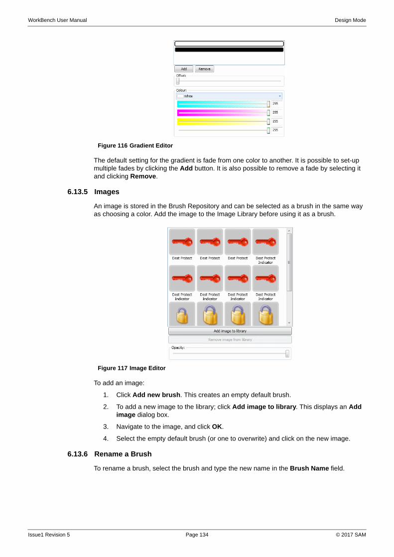
WorkBench User Manual Design Mode
The default setting for the gradient is fade from one color to another. It is possible to set-up multiple fades by clicking the Add button. It is also possible to remove a fade by selecting it and clicking Remove.
6.13.5 Images
An image is stored in the Brush Repository and can be selected as a brush in the same way as choosing a color. Add the image to the Image Library before using it as a brush.
To add an image:
1. Click Add new brush. This creates an empty default brush.
2. To add a new image to the library; click Add image to library. This displays an Add image dialog box.
3. Navigate to the image, and click OK.
4. Select the empty default brush (or one to overwrite) and click on the new image.
6.13.6 Rename a Brush
To rename a brush, select the brush and type the new name in the Brush Name field.
Figure 116 Gradient Editor
Figure 117 Image Editor
Issue1 Revision 5 Page 134 © 2017 SAM
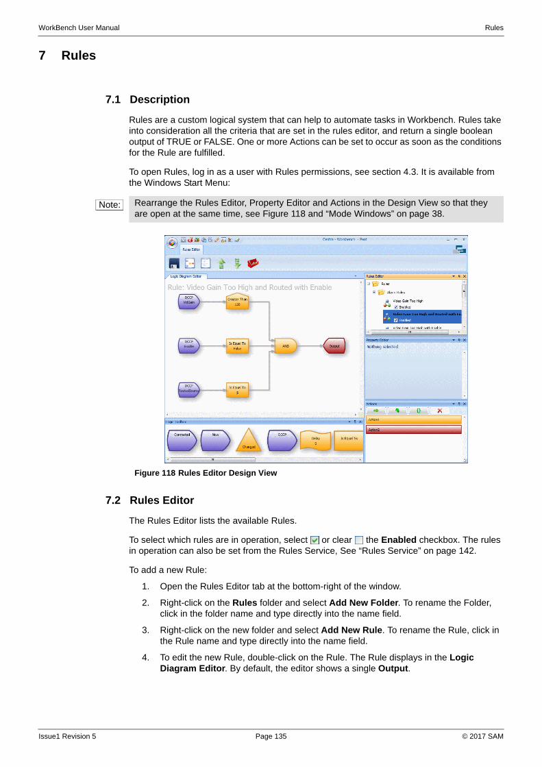
WorkBench User Manual Rules
7 Rules
7.1 Description
Rules are a custom logical system that can help to automate tasks in Workbench. Rules take into consideration all the criteria that are set in the rules editor, and return a single boolean output of TRUE or FALSE. One or more Actions can be set to occur as soon as the conditions for the Rule are fulfilled.
To open Rules, log in as a user with Rules permissions, see section 4.3. It is available from the Windows Start Menu:
7.2 Rules Editor
The Rules Editor lists the available Rules.
To select which rules are in operation, select or clear the Enabled checkbox. The rules in operation can also be set from the Rules Service, See “Rules Service” on page 142.
To add a new Rule:
1. Open the Rules Editor tab at the bottom-right of the window.
2. Right-click on the Rules folder and select Add New Folder. To rename the Folder, click in the folder name and type directly into the name field.
3. Right-click on the new folder and select Add New Rule. To rename the Rule, click in the Rule name and type directly into the name field.
4. To edit the new Rule, double-click on the Rule. The Rule displays in the Logic Diagram Editor. By default, the editor shows a single Output.
Note: Rearrange the Rules Editor, Property Editor and Actions in the Design View so that they are open at the same time, see Figure 118 and “Mode Windows” on page 38.
Figure 118 Rules Editor Design View
Issue1 Revision 5 Page 135 © 2017 SAM
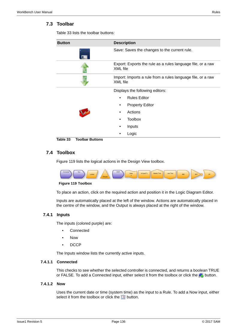
WorkBench User Manual Rules
7.3 Toolbar
Table 33 lists the toolbar buttons:
7.4 Toolbox
Figure 119 lists the logical actions in the Design View toolbox.
To place an action, click on the required action and position it in the Logic Diagram Editor.
Inputs are automatically placed at the left of the window. Actions are automatically placed in the centre of the window, and the Output is always placed at the right of the window.
7.4.1 Inputs
The inputs (colored purple) are:
• Connected
• Now
• DCCP
The Inputs window lists the currently active inputs.
7.4.1.1 Connected
This checks to see whether the selected controller is connected, and returns a boolean TRUE or FALSE. To add a Connected input, either select it from the toolbox or click the button.
7.4.1.2 Now
Uses the current date or time (system time) as the input to a Rule. To add a Now input, either select it from the toolbox or click the button.
Button Description
Save: Saves the changes to the current rule.
Export: Exports the rule as a rules language file, or a raw XML file
Import: Imports a rule from a rules language file, or a raw XML file
Displays the following editors:
• Rules Editor
• Property Editor
• Actions
• Toolbox
• Inputs
• Logic
Table 33 Toolbar Buttons
Figure 119 Toolbox
Issue1 Revision 5 Page 136 © 2017 SAM
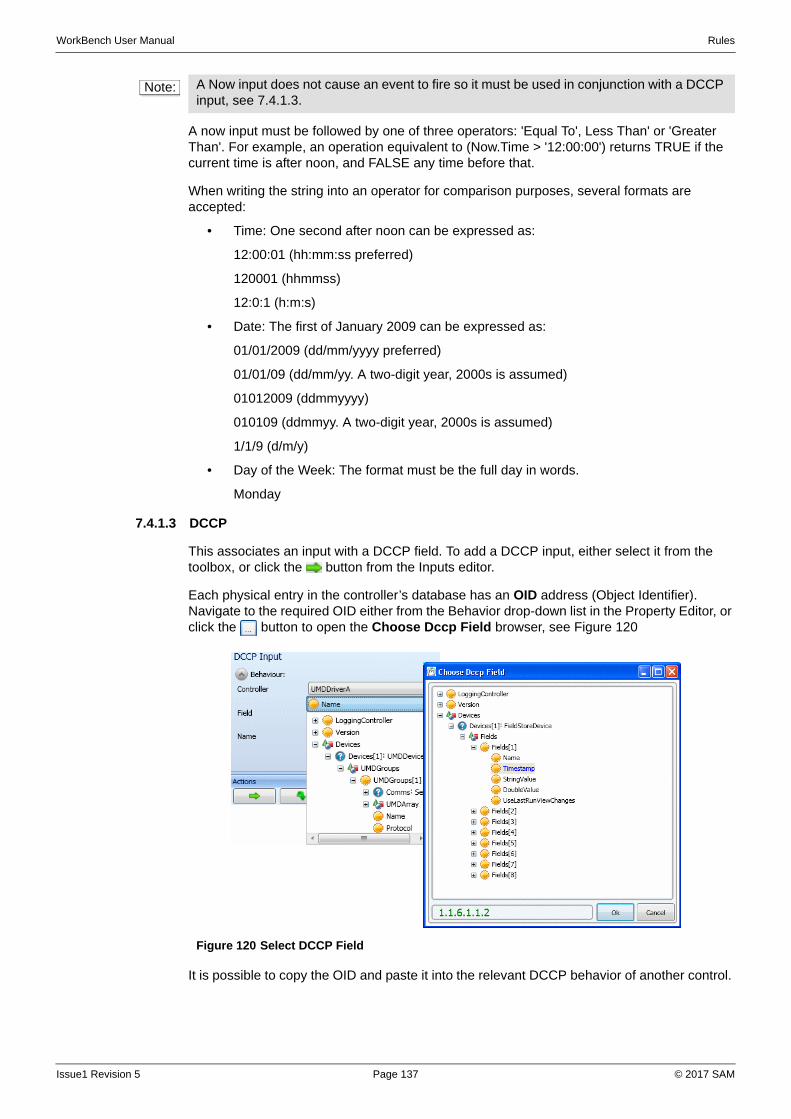
WorkBench User Manual Rules
A now input must be followed by one of three operators: 'Equal To', Less Than' or 'Greater Than'. For example, an operation equivalent to (Now.Time > '12:00:00') returns TRUE if the current time is after noon, and FALSE any time before that.
When writing the string into an operator for comparison purposes, several formats are accepted:
• Time: One second after noon can be expressed as:
12:00:01 (hh:mm:ss preferred)
120001 (hhmmss)
12:0:1 (h:m:s)
• Date: The first of January 2009 can be expressed as:
01/01/2009 (dd/mm/yyyy preferred)
01/01/09 (dd/mm/yy. A two-digit year, 2000s is assumed)
01012009 (ddmmyyyy)
010109 (ddmmyy. A two-digit year, 2000s is assumed)
1/1/9 (d/m/y)
• Day of the Week: The format must be the full day in words.
Monday
7.4.1.3 DCCP
This associates an input with a DCCP field. To add a DCCP input, either select it from the toolbox, or click the button from the Inputs editor.
Each physical entry in the controller’s database has an OID address (Object Identifier). Navigate to the required OID either from the Behavior drop-down list in the Property Editor, or click the button to open the Choose Dccp Field browser, see Figure 120
It is possible to copy the OID and paste it into the relevant DCCP behavior of another control.
Note: A Now input does not cause an event to fire so it must be used in conjunction with a DCCP input, see 7.4.1.3.
Figure 120 Select DCCP Field
Issue1 Revision 5 Page 137 © 2017 SAM
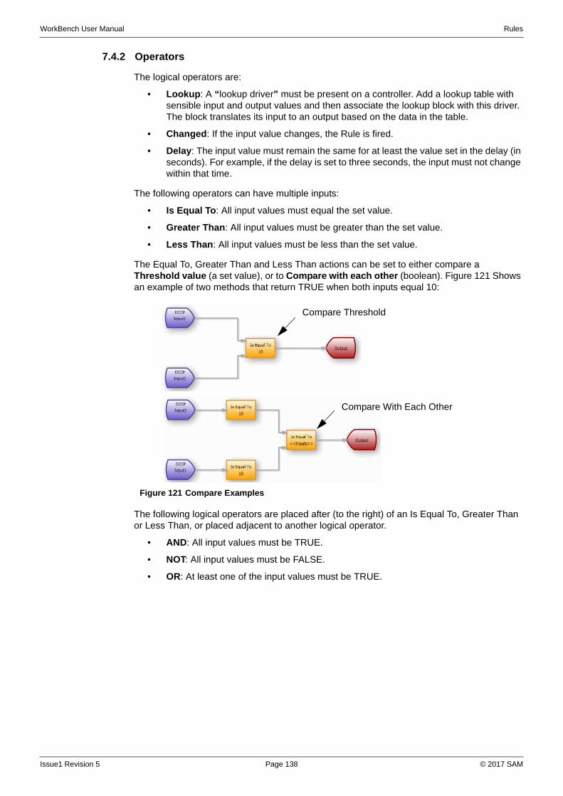
WorkBench User Manual Rules
7.4.2 Operators
The logical operators are:
• Lookup: A “lookup driver” must be present on a controller. Add a lookup table with sensible input and output values and then associate the lookup block with this driver. The block translates its input to an output based on the data in the table.
• Changed: If the input value changes, the Rule is fired.
• Delay: The input value must remain the same for at least the value set in the delay (in seconds). For example, if the delay is set to three seconds, the input must not change within that time.
The following operators can have multiple inputs:
• Is Equal To: All input values must equal the set value.
• Greater Than: All input values must be greater than the set value.
• Less Than: All input values must be less than the set value.
The Equal To, Greater Than and Less Than actions can be set to either compare a Threshold value (a set value), or to Compare with each other (boolean). Figure 121 Shows an example of two methods that return TRUE when both inputs equal 10:
The following logical operators are placed after (to the right) of an Is Equal To, Greater Than or Less Than, or placed adjacent to another logical operator.
• AND: All input values must be TRUE.
• NOT: All input values must be FALSE.
• OR: At least one of the input values must be TRUE.
Figure 121 Compare Examples
Compare Threshold
Compare With Each Other
Issue1 Revision 5 Page 138 © 2017 SAM
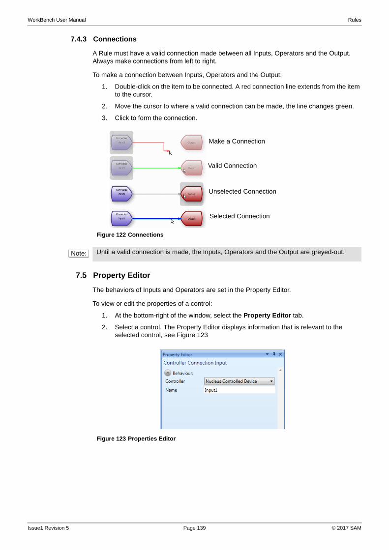
WorkBench User Manual Rules
7.4.3 Connections
A Rule must have a valid connection made between all Inputs, Operators and the Output. Always make connections from left to right.
To make a connection between Inputs, Operators and the Output:
1. Double-click on the item to be connected. A red connection line extends from the item to the cursor.
2. Move the cursor to where a valid connection can be made, the line changes green.
3. Click to form the connection.
7.5 Property Editor
The behaviors of Inputs and Operators are set in the Property Editor.
To view or edit the properties of a control:
1. At the bottom-right of the window, select the Property Editor tab.
2. Select a control. The Property Editor displays information that is relevant to the selected control, see Figure 123
Figure 122 Connections
Note: Until a valid connection is made, the Inputs, Operators and the Output are greyed-out.
Make a Connection
Valid Connection
Unselected Connection
Selected Connection
Figure 123 Properties Editor
Issue1 Revision 5 Page 139 © 2017 SAM
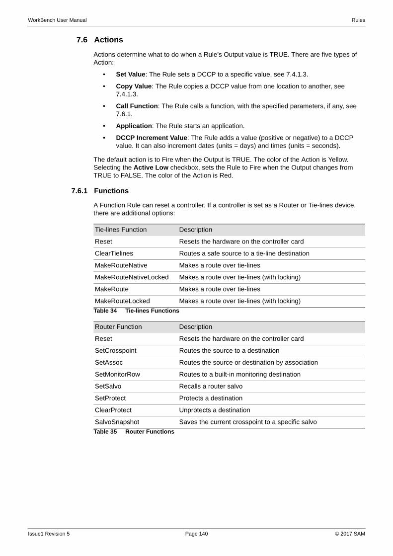
WorkBench User Manual Rules
7.6 Actions
Actions determine what to do when a Rule’s Output value is TRUE. There are five types of Action:
• Set Value: The Rule sets a DCCP to a specific value, see 7.4.1.3.
• Copy Value: The Rule copies a DCCP value from one location to another, see 7.4.1.3.
• Call Function: The Rule calls a function, with the specified parameters, if any, see 7.6.1.
• Application: The Rule starts an application.
• DCCP Increment Value: The Rule adds a value (positive or negative) to a DCCP value. It can also increment dates (units = days) and times (units = seconds).
The default action is to Fire when the Output is TRUE. The color of the Action is Yellow. Selecting the Active Low checkbox, sets the Rule to Fire when the Output changes from TRUE to FALSE. The color of the Action is Red.
7.6.1 Functions
A Function Rule can reset a controller. If a controller is set as a Router or Tie-lines device, there are additional options:
Tie-lines Function Description
Reset Resets the hardware on the controller card
ClearTielines Routes a safe source to a tie-line destination
MakeRouteNative Makes a route over tie-lines
MakeRouteNativeLocked Makes a route over tie-lines (with locking)
MakeRoute Makes a route over tie-lines
MakeRouteLocked Makes a route over tie-lines (with locking)
Table 34 Tie-lines Functions
Router Function Description
Reset Resets the hardware on the controller card
SetCrosspoint Routes the source to a destination
SetAssoc Routes the source or destination by association
SetMonitorRow Routes to a built-in monitoring destination
SetSalvo Recalls a router salvo
SetProtect Protects a destination
ClearProtect Unprotects a destination
SalvoSnapshot Saves the current crosspoint to a specific salvo
Table 35 Router Functions
Issue1 Revision 5 Page 140 © 2017 SAM
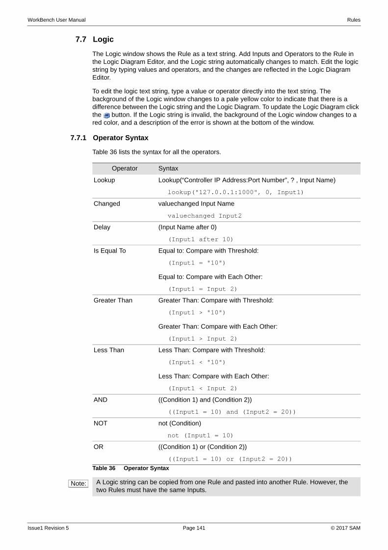
WorkBench User Manual Rules
7.7 Logic
The Logic window shows the Rule as a text string. Add Inputs and Operators to the Rule in the Logic Diagram Editor, and the Logic string automatically changes to match. Edit the logic string by typing values and operators, and the changes are reflected in the Logic Diagram Editor.
To edit the logic text string, type a value or operator directly into the text string. The background of the Logic window changes to a pale yellow color to indicate that there is a difference between the Logic string and the Logic Diagram. To update the Logic Diagram click the button. If the Logic string is invalid, the background of the Logic window changes to a red color, and a description of the error is shown at the bottom of the window.
7.7.1 Operator Syntax
Table 36 lists the syntax for all the operators.
Operator Syntax
Lookup Lookup(“Controller IP Address:Port Number”, ? , Input Name)
lookup("127.0.0.1:1000", 0, Input1)
Changed valuechanged Input Name
valuechanged Input2
Delay (Input Name after 0)
(Input1 after 10)
Is Equal To Equal to: Compare with Threshold:
(Input1 = "10")
Equal to: Compare with Each Other:
(Input1 = Input 2)
Greater Than Greater Than: Compare with Threshold:
(Input1 > "10")
Greater Than: Compare with Each Other:
(Input1 > Input 2)
Less Than Less Than: Compare with Threshold:
(Input1 < "10")
Less Than: Compare with Each Other:
(Input1 < Input 2)
AND ((Condition 1) and (Condition 2))
((Input1 = 10) and (Input2 = 20))
NOT not (Condition)
not (Input1 = 10)
OR ((Condition 1) or (Condition 2))
((Input1 = 10) or (Input2 = 20))
Table 36 Operator Syntax
Note: A Logic string can be copied from one Rule and pasted into another Rule. However, the two Rules must have the same Inputs.
Issue1 Revision 5 Page 141 © 2017 SAM
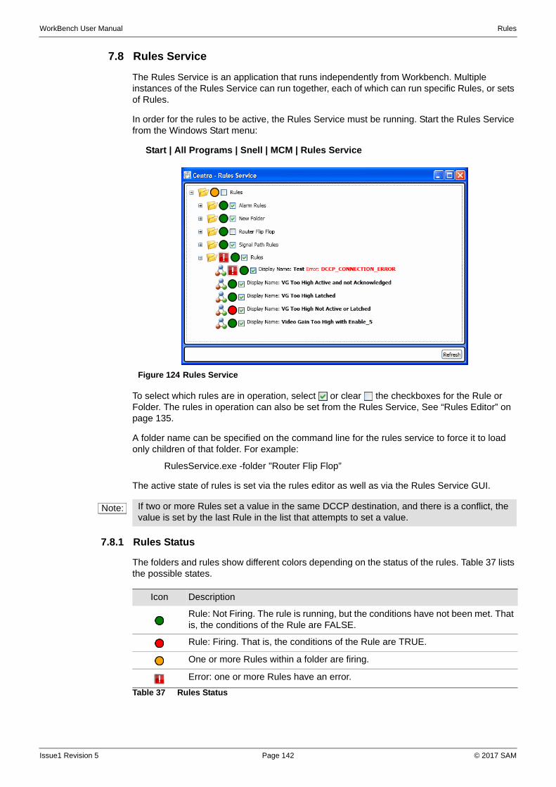
WorkBench User Manual Rules
7.8 Rules Service
The Rules Service is an application that runs independently from Workbench. Multiple instances of the Rules Service can run together, each of which can run specific Rules, or sets of Rules.
In order for the rules to be active, the Rules Service must be running. Start the Rules Service from the Windows Start menu:
Start | All Programs | Snell | MCM | Rules Service
To select which rules are in operation, select or clear the checkboxes for the Rule or Folder. The rules in operation can also be set from the Rules Service, See “Rules Editor” on page 135.
A folder name can be specified on the command line for the rules service to force it to load only children of that folder. For example:
RulesService.exe -folder "Router Flip Flop”
The active state of rules is set via the rules editor as well as via the Rules Service GUI.
7.8.1 Rules Status
The folders and rules show different colors depending on the status of the rules. Table 37 lists the possible states.
Figure 124 Rules Service
Note: If two or more Rules set a value in the same DCCP destination, and there is a conflict, the value is set by the last Rule in the list that attempts to set a value.
Icon Description
Rule: Not Firing. The rule is running, but the conditions have not been met. That is, the conditions of the Rule are FALSE.
Rule: Firing. That is, the conditions of the Rule are TRUE.
One or more Rules within a folder are firing.
Error: one or more Rules have an error.
Table 37 Rules Status
Issue1 Revision 5 Page 142 © 2017 SAM
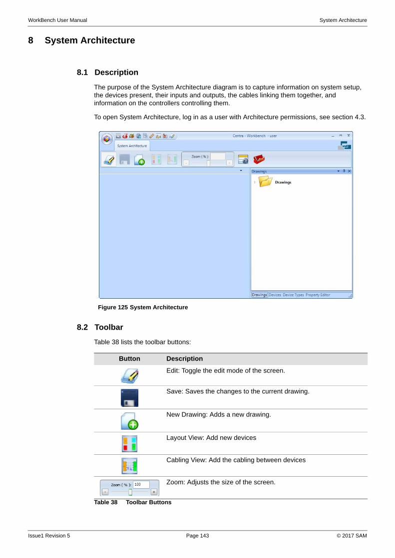
WorkBench User Manual System Architecture
8 System Architecture
8.1 Description
The purpose of the System Architecture diagram is to capture information on system setup, the devices present, their inputs and outputs, the cables linking them together, and information on the controllers controlling them.
To open System Architecture, log in as a user with Architecture permissions, see section 4.3.
8.2 Toolbar
Table 38 lists the toolbar buttons:
Figure 125 System Architecture
Button Description
Edit: Toggle the edit mode of the screen.
Save: Saves the changes to the current drawing.
New Drawing: Adds a new drawing.
Layout View: Add new devices
Cabling View: Add the cabling between devices
Zoom: Adjusts the size of the screen.
Table 38 Toolbar Buttons
Issue1 Revision 5 Page 143 © 2017 SAM
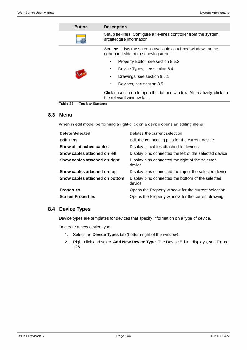
WorkBench User Manual System Architecture
8.3 Menu
When in edit mode, performing a right-click on a device opens an editing menu:
8.4 Device Types
Device types are templates for devices that specify information on a type of device.
To create a new device type:
1. Select the Device Types tab (bottom-right of the window).
2. Right-click and select Add New Device Type. The Device Editor displays, see Figure 126
Setup tie-lines: Configure a tie-lines controller from the system architecture information
Screens: Lists the screens available as tabbed windows at the right-hand side of the drawing area:
• Property Editor, see section 8.5.2
• Device Types, see section 8.4
• Drawings, see section 8.5.1
• Devices, see section 8.5
Click on a screen to open that tabbed window. Alternatively, click on the relevant window tab.
Button Description
Table 38 Toolbar Buttons
Delete Selected Deletes the current selection
Edit Pins Edit the connecting pins for the current device
Show all attached cables Display all cables attached to devices
Show cables attached on left Display pins connected the left of the selected device
Show cables attached on right Display pins connected the right of the selected device
Show cables attached on top Display pins connected the top of the selected device
Show cables attached on bottom Display pins connected the bottom of the selected device
Properties Opens the Property window for the current selection
Screen Properties Opens the Property window for the current drawing
Issue1 Revision 5 Page 144 © 2017 SAM
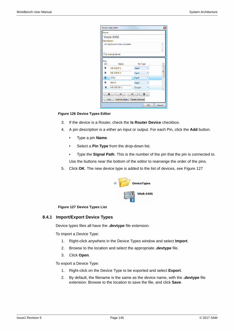
WorkBench User Manual System Architecture
3. If the device is a Router, check the Is Router Device checkbox.
4. A pin description is a either an input or output. For each Pin, click the Add button.
• Type a pin Name.
• Select a Pin Type from the drop-down list.
• Type the Signal Path. This is the number of the pin that the pin is connected to.
Use the buttons near the bottom of the editor to rearrange the order of the pins.
5. Click OK. The new device type is added to the list of devices, see Figure 127
8.4.1 Import/Export Device Types
Device types files all have the .devtype file extension.
To import a Device Type:
1. Right-click anywhere in the Device Types window and select Import.
2. Browse to the location and select the appropriate .devtype file.
3. Click Open.
To export a Device Type:
1. Right-click on the Device Type to be exported and select Export.
2. By default, the filename is the same as the device name, with the .devtype file extension. Browse to the location to save the file, and click Save.
Figure 126 Device Types Editor
Figure 127 Device Types List
Issue1 Revision 5 Page 145 © 2017 SAM

WorkBench User Manual System Architecture
8.5 Devices
Devices and cables exist independently of drawings. Adding a device to a drawing does not create a new device, it simply copies that particular device from list. Similarly, removing a device from a drawing does not delete that device from the list.
The Device tab shows all the available devices. Multiple devices can be placed on a single drawing, and a device can be placed on multiple drawings.
To add a new device.
1. Select the Device tab (bottom-right of the window).
2. Right-click and select Add New Device. The Create Device wizard displays.
3. Type a unique name for the device, and click Next.
4. Select whether to:
Create a new device based on a device type
a Select the Device type from the drop-down list.
Create a new device based on a router matrix
a Select the Controller from the drop-down list.
b Select the Matrix from the drop-down list.
5. Click OK. The new device is added to the list of devices, see Figure 128
8.5.1 Add a Device to a Drawing
To add a device to a drawing:
1. Select the Drawings tab (bottom-right of the window).
2. Double-click on the required drawing.
3. On the toolbar, click the button, and the button.
4. Select the Device tab (bottom-right of the window).
5. Double-click on the device to be added.
6. Drag and place the device on the drawing, see Figure 129
8.5.2 Device Properties
To view or edit the properties of a device, open the property editor tab (bottom-right of the window).
Figure 128 Devices List
Figure 129 Example Device
Issue1 Revision 5 Page 146 © 2017 SAM
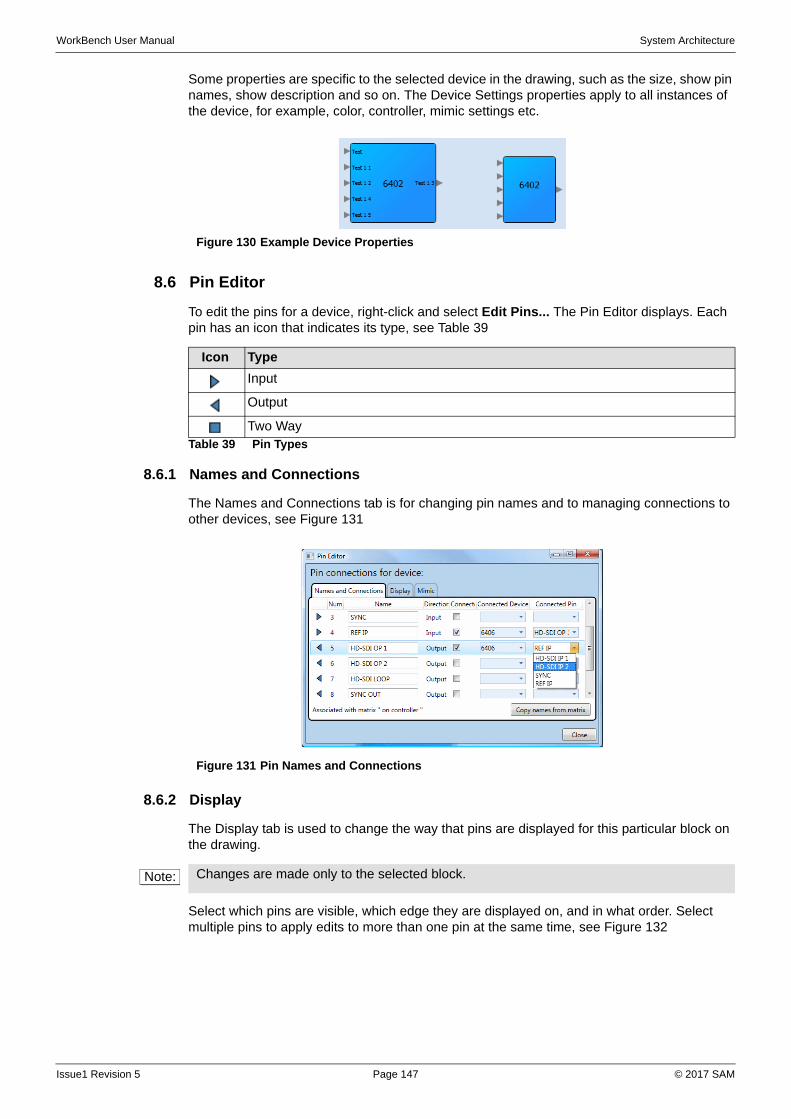
WorkBench User Manual System Architecture
Some properties are specific to the selected device in the drawing, such as the size, show pin names, show description and so on. The Device Settings properties apply to all instances of the device, for example, color, controller, mimic settings etc.
8.6 Pin Editor
To edit the pins for a device, right-click and select Edit Pins... The Pin Editor displays. Each pin has an icon that indicates its type, see Table 39
8.6.1 Names and Connections
The Names and Connections tab is for changing pin names and to managing connections to other devices, see Figure 131
8.6.2 Display
The Display tab is used to change the way that pins are displayed for this particular block on the drawing.
Select which pins are visible, which edge they are displayed on, and in what order. Select multiple pins to apply edits to more than one pin at the same time, see Figure 132
Figure 130 Example Device Properties
Icon Type
Input
Output
Two WayTable 39 Pin Types
Figure 131 Pin Names and Connections
Note: Changes are made only to the selected block.
Issue1 Revision 5 Page 147 © 2017 SAM
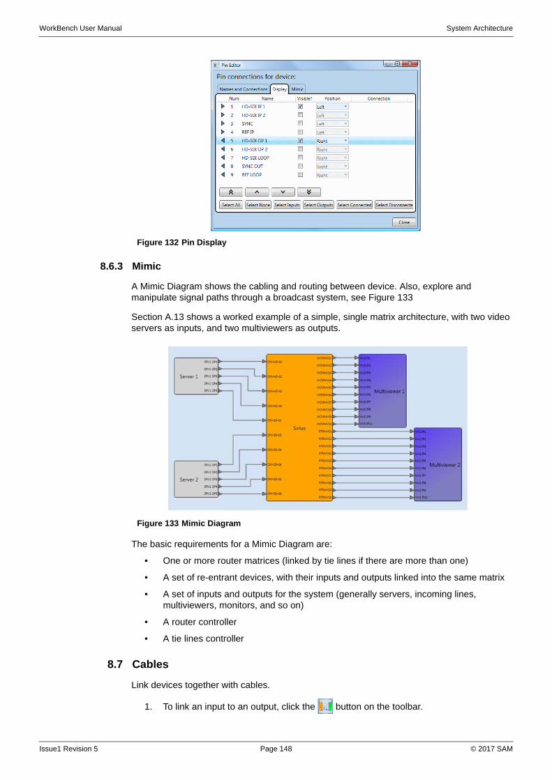
WorkBench User Manual System Architecture
8.6.3 Mimic
A Mimic Diagram shows the cabling and routing between device. Also, explore and manipulate signal paths through a broadcast system, see Figure 133
Section A.13 shows a worked example of a simple, single matrix architecture, with two video servers as inputs, and two multiviewers as outputs.
The basic requirements for a Mimic Diagram are:
• One or more router matrices (linked by tie lines if there are more than one)
• A set of re-entrant devices, with their inputs and outputs linked into the same matrix
• A set of inputs and outputs for the system (generally servers, incoming lines, multiviewers, monitors, and so on)
• A router controller
• A tie lines controller
8.7 Cables
Link devices together with cables.
1. To link an input to an output, click the button on the toolbar.
Figure 132 Pin Display
Figure 133 Mimic Diagram
Issue1 Revision 5 Page 148 © 2017 SAM
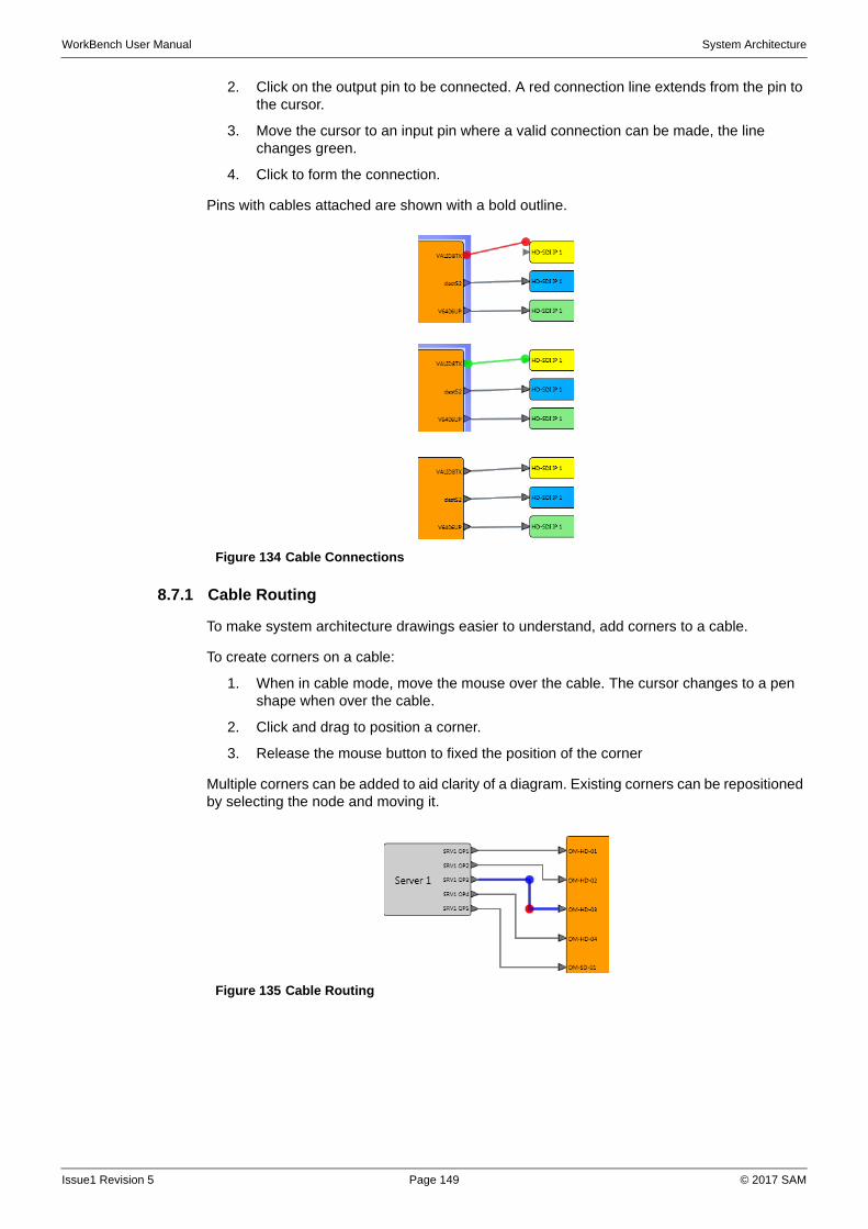
WorkBench User Manual System Architecture
2. Click on the output pin to be connected. A red connection line extends from the pin to the cursor.
3. Move the cursor to an input pin where a valid connection can be made, the line changes green.
4. Click to form the connection.
Pins with cables attached are shown with a bold outline.
8.7.1 Cable Routing
To make system architecture drawings easier to understand, add corners to a cable.
To create corners on a cable:
1. When in cable mode, move the mouse over the cable. The cursor changes to a pen shape when over the cable.
2. Click and drag to position a corner.
3. Release the mouse button to fixed the position of the corner
Multiple corners can be added to aid clarity of a diagram. Existing corners can be repositioned by selecting the node and moving it.
Figure 134 Cable Connections
Figure 135 Cable Routing
Issue1 Revision 5 Page 149 © 2017 SAM

WorkBench User Manual System Architecture
Issue1 Revision 5 Page 150 © 2017 SAM

WorkBench User Manual Worked Examples
Appendix A Worked Examples
The following examples assume a working installation and pre-configured controllers.
A.1 XY Soft Panel
A.1.1 Create New Panel
Figure 136 shows the finished panel; it has four sources and four destinations. The route for each signal is set by selecting a destination, then a source, and clicking the Take button.
Prerequisites: A device controller (or simulator) must be attached for the following procedure to work correctly.
A.1.1.1 Add New Screen
1. Open the Workbench Design window.
2. At the bottom-right of the window, select the Screens Editor tab.
3. Either on the Screens Editor tab click the Add button, or on the toolbar click the button. The Add New Screen dialog box displays. Type a name for the new screen (for example, Screen 1) and click OK. The new screen is added to the list.
A.1.1.2 Modify Screen Properties
1. On the toolbar, click the button. The Toolbox displays at the bottom of the window.
2. Next to the Screens Editor tab, select the Property Window tab. Alternatively, right-click anywhere outside the panel and select Screen Properties.
3. Change the size of the screen to 390 x 560 (all dimensions are in pixels).
Figure 136 XY Panel With a Take Button
Note: By default, the first time the Design window is opened, the first screen in the list is shown. Subsequently, the design view displays the default screen.
Note: To open any screen in the list, double-click on the thumbnail. Only one screen can be open at a time.
Issue1 Revision 5 Page 151 © 2017 SAM
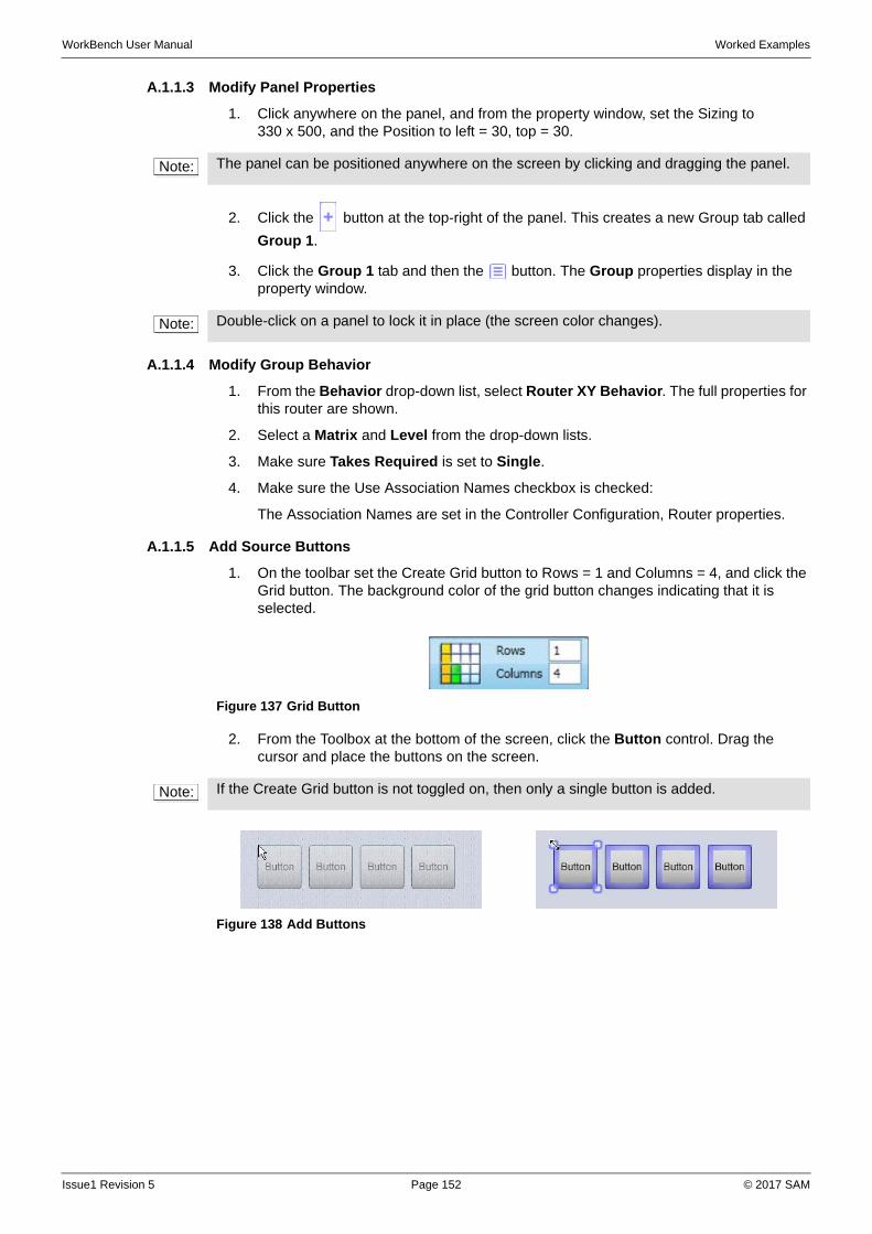
WorkBench User Manual Worked Examples
A.1.1.3 Modify Panel Properties
1. Click anywhere on the panel, and from the property window, set the Sizing to 330 x 500, and the Position to left = 30, top = 30.
2. Click the button at the top-right of the panel. This creates a new Group tab called
Group 1.
3. Click the Group 1 tab and then the button. The Group properties display in the property window.
A.1.1.4 Modify Group Behavior
1. From the Behavior drop-down list, select Router XY Behavior. The full properties for this router are shown.
2. Select a Matrix and Level from the drop-down lists.
3. Make sure Takes Required is set to Single.
4. Make sure the Use Association Names checkbox is checked:
The Association Names are set in the Controller Configuration, Router properties.
A.1.1.5 Add Source Buttons
1. On the toolbar set the Create Grid button to Rows = 1 and Columns = 4, and click the Grid button. The background color of the grid button changes indicating that it is selected.
2. From the Toolbox at the bottom of the screen, click the Button control. Drag the cursor and place the buttons on the screen.
Note: The panel can be positioned anywhere on the screen by clicking and dragging the panel.
Note: Double-click on a panel to lock it in place (the screen color changes).
Figure 137 Grid Button
Note: If the Create Grid button is not toggled on, then only a single button is added.
Figure 138 Add Buttons
Issue1 Revision 5 Page 152 © 2017 SAM
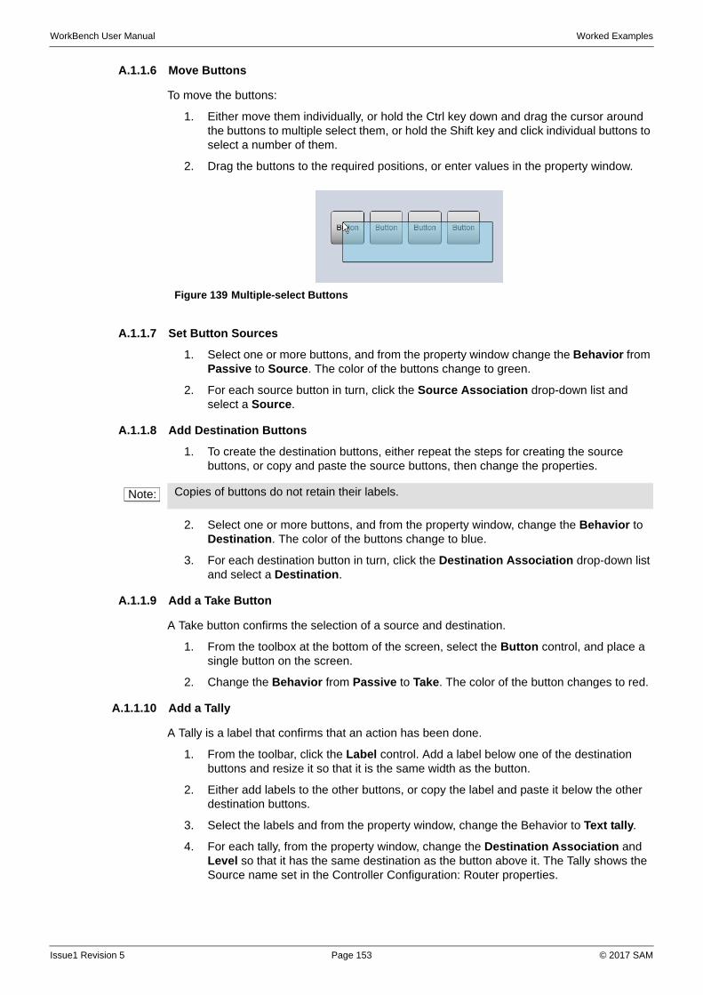
WorkBench User Manual Worked Examples
A.1.1.6 Move Buttons
To move the buttons:
1. Either move them individually, or hold the Ctrl key down and drag the cursor around the buttons to multiple select them, or hold the Shift key and click individual buttons to select a number of them.
2. Drag the buttons to the required positions, or enter values in the property window.
A.1.1.7 Set Button Sources
1. Select one or more buttons, and from the property window change the Behavior from Passive to Source. The color of the buttons change to green.
2. For each source button in turn, click the Source Association drop-down list and select a Source.
A.1.1.8 Add Destination Buttons
1. To create the destination buttons, either repeat the steps for creating the source buttons, or copy and paste the source buttons, then change the properties.
2. Select one or more buttons, and from the property window, change the Behavior to Destination. The color of the buttons change to blue.
3. For each destination button in turn, click the Destination Association drop-down list and select a Destination.
A.1.1.9 Add a Take Button
A Take button confirms the selection of a source and destination.
1. From the toolbox at the bottom of the screen, select the Button control, and place a single button on the screen.
2. Change the Behavior from Passive to Take. The color of the button changes to red.
A.1.1.10 Add a Tally
A Tally is a label that confirms that an action has been done.
1. From the toolbar, click the Label control. Add a label below one of the destination buttons and resize it so that it is the same width as the button.
2. Either add labels to the other buttons, or copy the label and paste it below the other destination buttons.
3. Select the labels and from the property window, change the Behavior to Text tally.
4. For each tally, from the property window, change the Destination Association and Level so that it has the same destination as the button above it. The Tally shows the Source name set in the Controller Configuration: Router properties.
Figure 139 Multiple-select Buttons
Note: Copies of buttons do not retain their labels.
Issue1 Revision 5 Page 153 © 2017 SAM
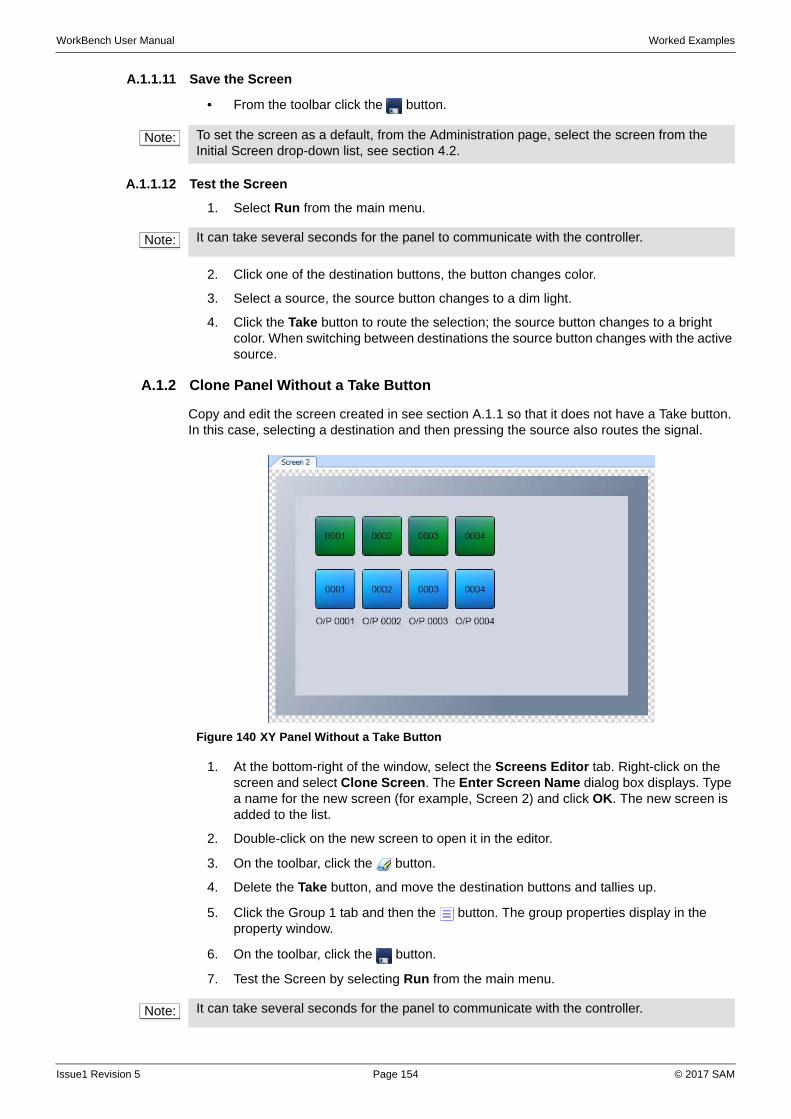
WorkBench User Manual Worked Examples
A.1.1.11 Save the Screen
• From the toolbar click the button.
A.1.1.12 Test the Screen
1. Select Run from the main menu.
2. Click one of the destination buttons, the button changes color.
3. Select a source, the source button changes to a dim light.
4. Click the Take button to route the selection; the source button changes to a bright color. When switching between destinations the source button changes with the active source.
A.1.2 Clone Panel Without a Take Button
Copy and edit the screen created in see section A.1.1 so that it does not have a Take button. In this case, selecting a destination and then pressing the source also routes the signal.
1. At the bottom-right of the window, select the Screens Editor tab. Right-click on the screen and select Clone Screen. The Enter Screen Name dialog box displays. Type a name for the new screen (for example, Screen 2) and click OK. The new screen is added to the list.
2. Double-click on the new screen to open it in the editor.
3. On the toolbar, click the button.
4. Delete the Take button, and move the destination buttons and tallies up.
5. Click the Group 1 tab and then the button. The group properties display in the property window.
6. On the toolbar, click the button.
7. Test the Screen by selecting Run from the main menu.
Note: To set the screen as a default, from the Administration page, select the screen from the Initial Screen drop-down list, see section 4.2.
Note: It can take several seconds for the panel to communicate with the controller.
Figure 140 XY Panel Without a Take Button
Note: It can take several seconds for the panel to communicate with the controller.
Issue1 Revision 5 Page 154 © 2017 SAM
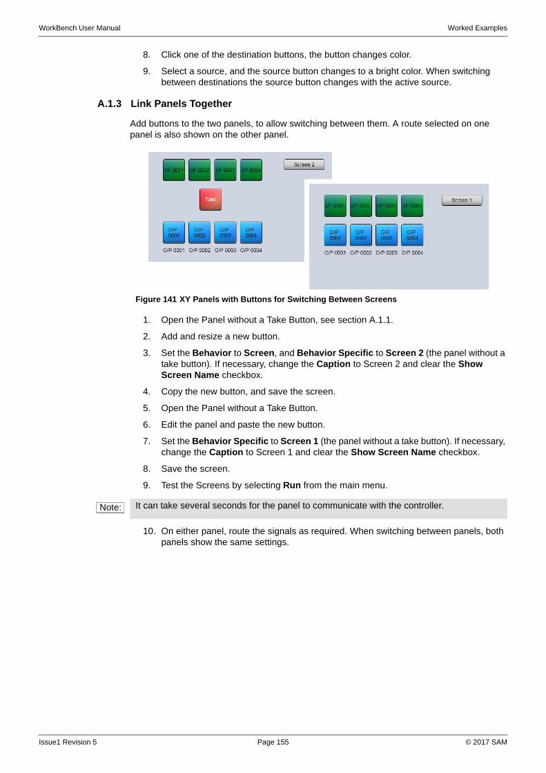
WorkBench User Manual Worked Examples
8. Click one of the destination buttons, the button changes color.
9. Select a source, and the source button changes to a bright color. When switching between destinations the source button changes with the active source.
A.1.3 Link Panels Together
Add buttons to the two panels, to allow switching between them. A route selected on one panel is also shown on the other panel.
1. Open the Panel without a Take Button, see section A.1.1.
2. Add and resize a new button.
3. Set the Behavior to Screen, and Behavior Specific to Screen 2 (the panel without a take button). If necessary, change the Caption to Screen 2 and clear the Show Screen Name checkbox.
4. Copy the new button, and save the screen.
5. Open the Panel without a Take Button.
6. Edit the panel and paste the new button.
7. Set the Behavior Specific to Screen 1 (the panel without a take button). If necessary, change the Caption to Screen 1 and clear the Show Screen Name checkbox.
8. Save the screen.
9. Test the Screens by selecting Run from the main menu.
10. On either panel, route the signals as required. When switching between panels, both panels show the same settings.
Figure 141 XY Panels with Buttons for Switching Between Screens
Note: It can take several seconds for the panel to communicate with the controller.
Issue1 Revision 5 Page 155 © 2017 SAM
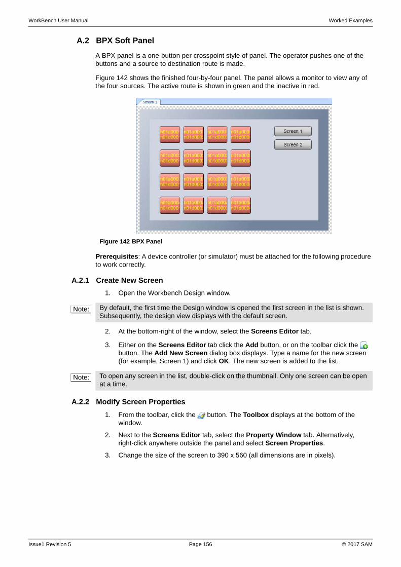
WorkBench User Manual Worked Examples
A.2 BPX Soft Panel
A BPX panel is a one-button per crosspoint style of panel. The operator pushes one of the buttons and a source to destination route is made.
Figure 142 shows the finished four-by-four panel. The panel allows a monitor to view any of the four sources. The active route is shown in green and the inactive in red.
Prerequisites: A device controller (or simulator) must be attached for the following procedure to work correctly.
A.2.1 Create New Screen
1. Open the Workbench Design window.
2. At the bottom-right of the window, select the Screens Editor tab.
3. Either on the Screens Editor tab click the Add button, or on the toolbar click the button. The Add New Screen dialog box displays. Type a name for the new screen (for example, Screen 1) and click OK. The new screen is added to the list.
A.2.2 Modify Screen Properties
1. From the toolbar, click the button. The Toolbox displays at the bottom of the window.
2. Next to the Screens Editor tab, select the Property Window tab. Alternatively, right-click anywhere outside the panel and select Screen Properties.
3. Change the size of the screen to 390 x 560 (all dimensions are in pixels).
Figure 142 BPX Panel
Note: By default, the first time the Design window is opened the first screen in the list is shown. Subsequently, the design view displays with the default screen.
Note: To open any screen in the list, double-click on the thumbnail. Only one screen can be open at a time.
Issue1 Revision 5 Page 156 © 2017 SAM
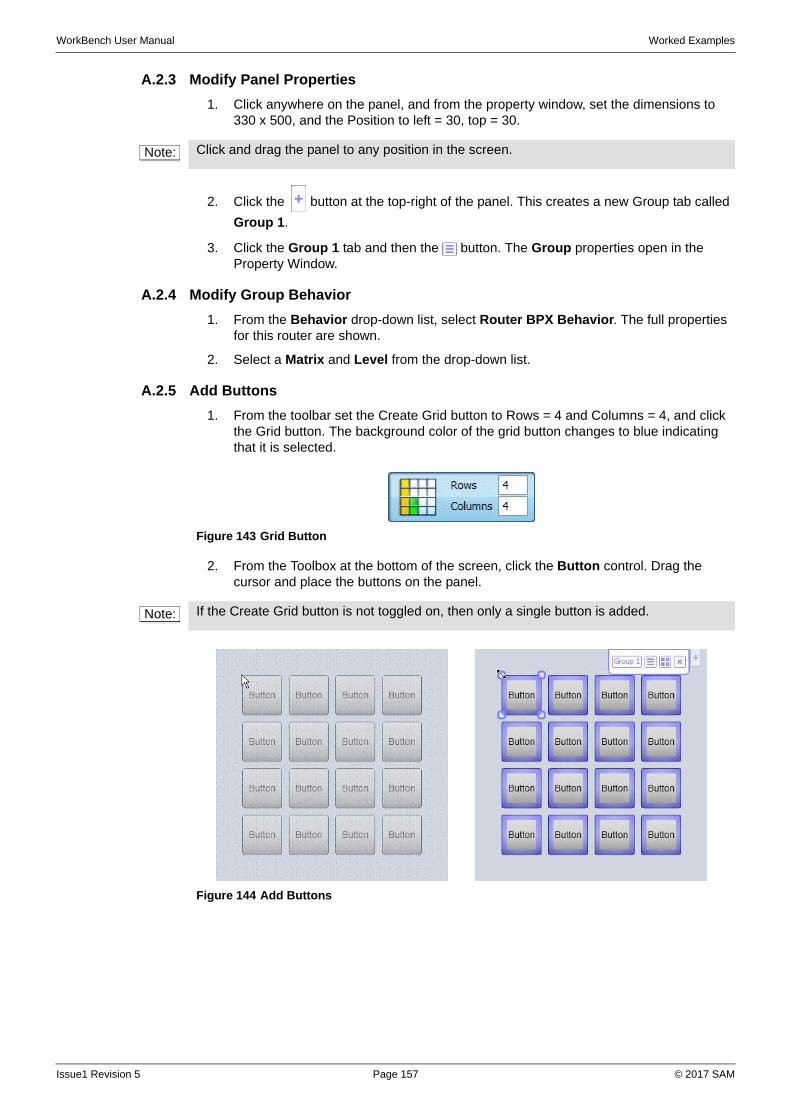
WorkBench User Manual Worked Examples
A.2.3 Modify Panel Properties
1. Click anywhere on the panel, and from the property window, set the dimensions to 330 x 500, and the Position to left = 30, top = 30.
2. Click the button at the top-right of the panel. This creates a new Group tab called
Group 1.
3. Click the Group 1 tab and then the button. The Group properties open in the Property Window.
A.2.4 Modify Group Behavior
1. From the Behavior drop-down list, select Router BPX Behavior. The full properties for this router are shown.
2. Select a Matrix and Level from the drop-down list.
A.2.5 Add Buttons
1. From the toolbar set the Create Grid button to Rows = 4 and Columns = 4, and click the Grid button. The background color of the grid button changes to blue indicating that it is selected.
2. From the Toolbox at the bottom of the screen, click the Button control. Drag the cursor and place the buttons on the panel.
Note: Click and drag the panel to any position in the screen.
Figure 143 Grid Button
Note: If the Create Grid button is not toggled on, then only a single button is added.
Figure 144 Add Buttons
Issue1 Revision 5 Page 157 © 2017 SAM
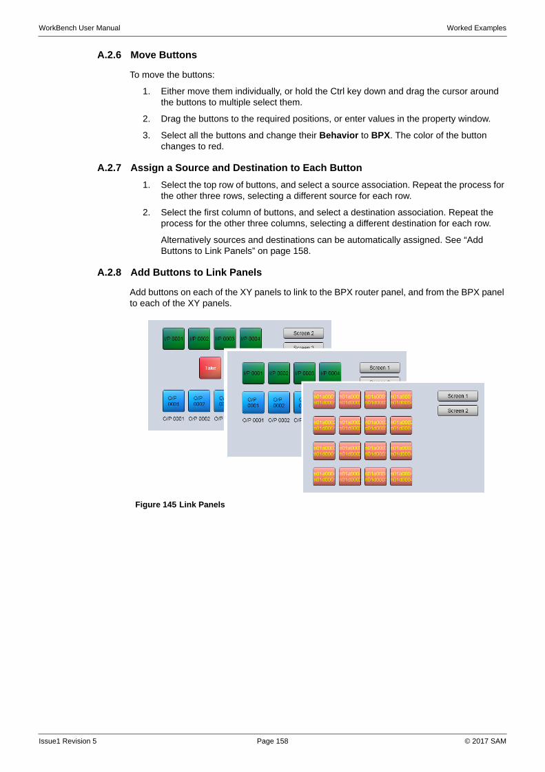
WorkBench User Manual Worked Examples
A.2.6 Move Buttons
To move the buttons:
1. Either move them individually, or hold the Ctrl key down and drag the cursor around the buttons to multiple select them.
2. Drag the buttons to the required positions, or enter values in the property window.
3. Select all the buttons and change their Behavior to BPX. The color of the button changes to red.
A.2.7 Assign a Source and Destination to Each Button
1. Select the top row of buttons, and select a source association. Repeat the process for the other three rows, selecting a different source for each row.
2. Select the first column of buttons, and select a destination association. Repeat the process for the other three columns, selecting a different destination for each row.
Alternatively sources and destinations can be automatically assigned. See “Add Buttons to Link Panels” on page 158.
A.2.8 Add Buttons to Link Panels
Add buttons on each of the XY panels to link to the BPX router panel, and from the BPX panel to each of the XY panels.
Figure 145 Link Panels
Issue1 Revision 5 Page 158 © 2017 SAM
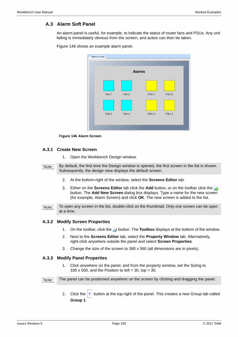
WorkBench User Manual Worked Examples
A.3 Alarm Soft Panel
An alarm panel is useful, for example, to indicate the status of router fans and PSUs. Any unit failing is immediately obvious from the screen, and action can then be taken.
Figure 146 shows an example alarm panel.
A.3.1 Create New Screen
1. Open the Workbench Design window.
2. At the bottom-right of the window, select the Screens Editor tab.
3. Either on the Screens Editor tab click the Add button, or on the toolbar click the button. The Add New Screen dialog box displays. Type a name for the new screen (for example, Alarm Screen) and click OK. The new screen is added to the list.
A.3.2 Modify Screen Properties
1. On the toolbar, click the button. The Toolbox displays at the bottom of the window.
2. Next to the Screens Editor tab, select the Property Window tab. Alternatively, right-click anywhere outside the panel and select Screen Properties.
3. Change the size of the screen to 390 x 560 (all dimensions are in pixels).
A.3.3 Modify Panel Properties
1. Click anywhere on the panel, and from the property window, set the Sizing to 330 x 500, and the Position to left = 30, top = 30.
2. Click the button at the top-right of the panel. This creates a new Group tab called
Group 1.
Figure 146 Alarm Screen
Note: By default, the first time the Design window is opened, the first screen in the list is shown. Subsequently, the design view displays the default screen.
Note: To open any screen in the list, double-click on the thumbnail. Only one screen can be open at a time.
Note: The panel can be positioned anywhere on the screen by clicking and dragging the panel.
Issue1 Revision 5 Page 159 © 2017 SAM
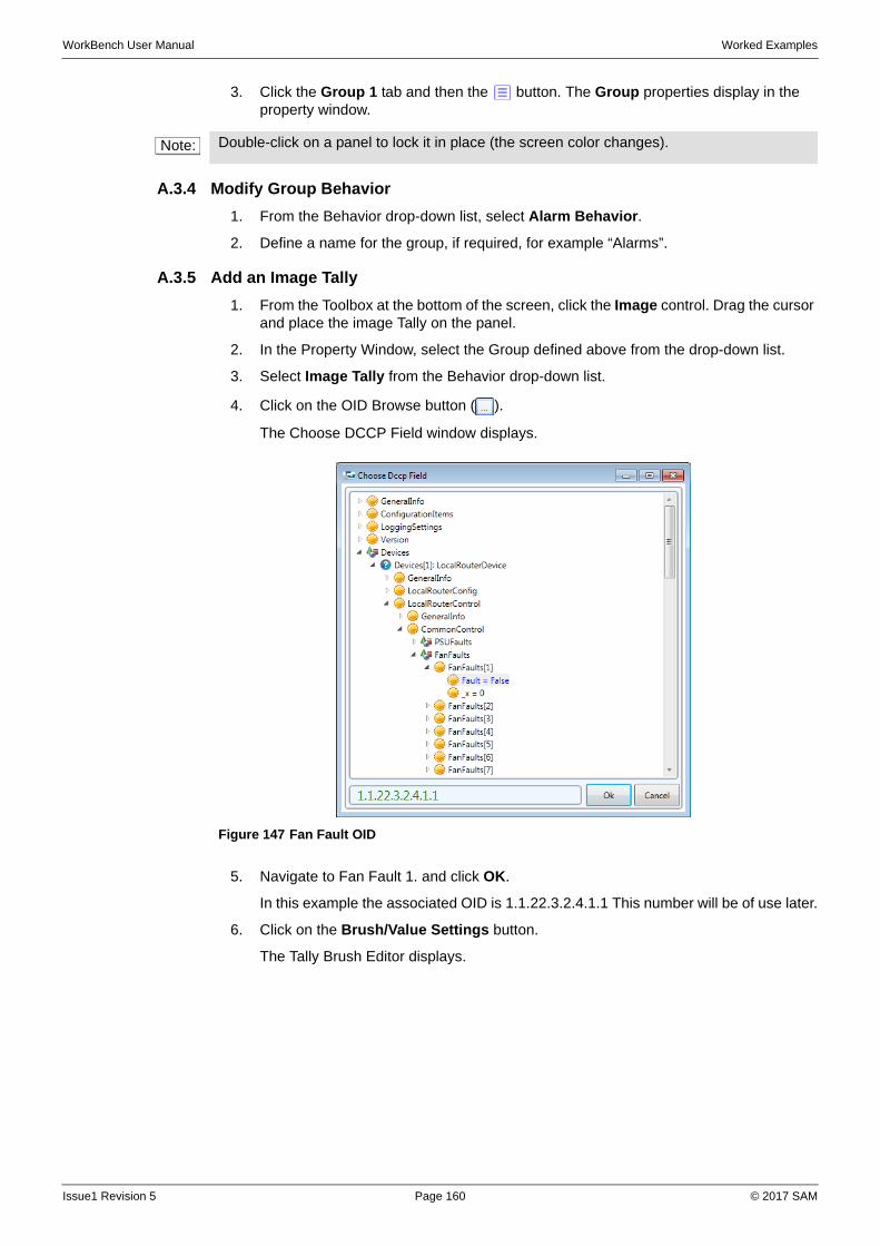
WorkBench User Manual Worked Examples
3. Click the Group 1 tab and then the button. The Group properties display in the property window.
A.3.4 Modify Group Behavior
1. From the Behavior drop-down list, select Alarm Behavior.
2. Define a name for the group, if required, for example “Alarms”.
A.3.5 Add an Image Tally
1. From the Toolbox at the bottom of the screen, click the Image control. Drag the cursor and place the image Tally on the panel.
2. In the Property Window, select the Group defined above from the drop-down list.
3. Select Image Tally from the Behavior drop-down list.
4. Click on the OID Browse button ( ).
The Choose DCCP Field window displays.
5. Navigate to Fan Fault 1. and click OK.
In this example the associated OID is 1.1.22.3.2.4.1.1 This number will be of use later.
6. Click on the Brush/Value Settings button.
The Tally Brush Editor displays.
Note: Double-click on a panel to lock it in place (the screen color changes).
Figure 147 Fan Fault OID
Issue1 Revision 5 Page 160 © 2017 SAM
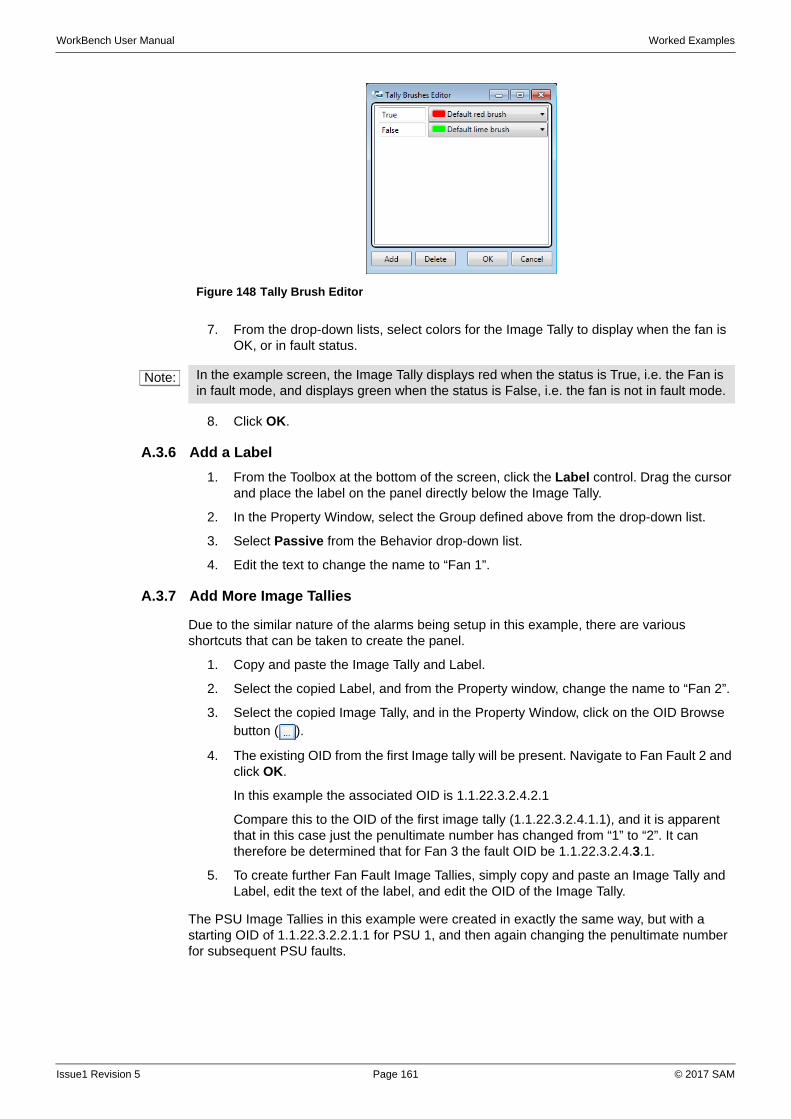
WorkBench User Manual Worked Examples
7. From the drop-down lists, select colors for the Image Tally to display when the fan is OK, or in fault status.
8. Click OK.
A.3.6 Add a Label
1. From the Toolbox at the bottom of the screen, click the Label control. Drag the cursor and place the label on the panel directly below the Image Tally.
2. In the Property Window, select the Group defined above from the drop-down list.
3. Select Passive from the Behavior drop-down list.
4. Edit the text to change the name to “Fan 1”.
A.3.7 Add More Image Tallies
Due to the similar nature of the alarms being setup in this example, there are various shortcuts that can be taken to create the panel.
1. Copy and paste the Image Tally and Label.
2. Select the copied Label, and from the Property window, change the name to “Fan 2”.
3. Select the copied Image Tally, and in the Property Window, click on the OID Browse button ( ).
4. The existing OID from the first Image tally will be present. Navigate to Fan Fault 2 and click OK.
In this example the associated OID is 1.1.22.3.2.4.2.1
Compare this to the OID of the first image tally (1.1.22.3.2.4.1.1), and it is apparent that in this case just the penultimate number has changed from “1” to “2”. It can therefore be determined that for Fan 3 the fault OID be 1.1.22.3.2.4.3.1.
5. To create further Fan Fault Image Tallies, simply copy and paste an Image Tally and Label, edit the text of the label, and edit the OID of the Image Tally.
The PSU Image Tallies in this example were created in exactly the same way, but with a starting OID of 1.1.22.3.2.2.1.1 for PSU 1, and then again changing the penultimate number for subsequent PSU faults.
Figure 148 Tally Brush Editor
Note: In the example screen, the Image Tally displays red when the status is True, i.e. the Fan is in fault mode, and displays green when the status is False, i.e. the fan is not in fault mode.
Issue1 Revision 5 Page 161 © 2017 SAM
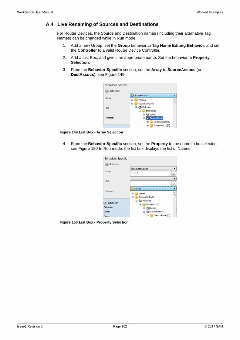
WorkBench User Manual Worked Examples
A.4 Live Renaming of Sources and Destinations
For Router Devices, the Source and Destination names (including their alternative Tag Names) can be changed while in Run mode.
1. Add a new Group, set the Group behavior to Tag Name Editing Behavior, and set the Controller to a valid Router Device Controller.
2. Add a List Box, and give it an appropriate name. Set the behavior to Property Selection.
3. From the Behavior Specific section, set the Array to SourceAssocs (or DestAssocs), see Figure 149
4. From the Behavior Specific section, set the Property to the name to be selected, see Figure 150 In Run mode, the list box displays the list of Names.
Figure 149 List Box - Array Selection
Figure 150 List Box - Property Selection
Issue1 Revision 5 Page 162 © 2017 SAM
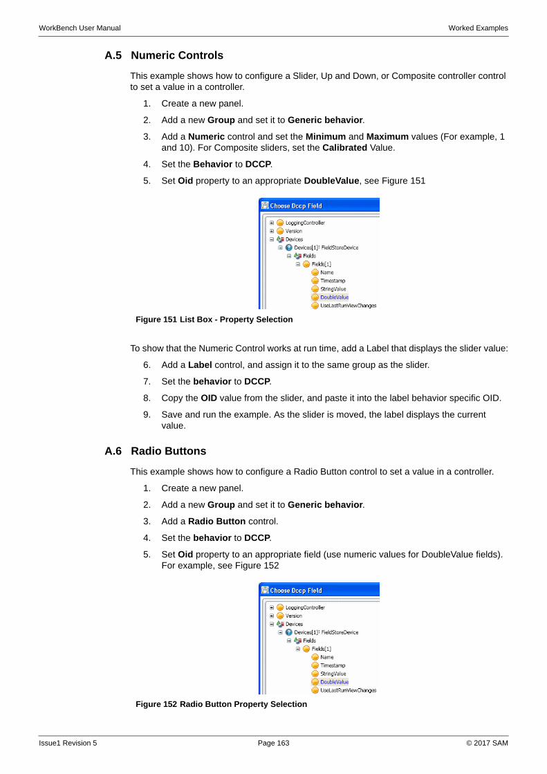
WorkBench User Manual Worked Examples
A.5 Numeric Controls
This example shows how to configure a Slider, Up and Down, or Composite controller control to set a value in a controller.
1. Create a new panel.
2. Add a new Group and set it to Generic behavior.
3. Add a Numeric control and set the Minimum and Maximum values (For example, 1 and 10). For Composite sliders, set the Calibrated Value.
4. Set the Behavior to DCCP.
5. Set Oid property to an appropriate DoubleValue, see Figure 151
To show that the Numeric Control works at run time, add a Label that displays the slider value:
6. Add a Label control, and assign it to the same group as the slider.
7. Set the behavior to DCCP.
8. Copy the OID value from the slider, and paste it into the label behavior specific OID.
9. Save and run the example. As the slider is moved, the label displays the current value.
A.6 Radio Buttons
This example shows how to configure a Radio Button control to set a value in a controller.
1. Create a new panel.
2. Add a new Group and set it to Generic behavior.
3. Add a Radio Button control.
4. Set the behavior to DCCP.
5. Set Oid property to an appropriate field (use numeric values for DoubleValue fields). For example, see Figure 152
Figure 151 List Box - Property Selection
Figure 152 Radio Button Property Selection
Issue1 Revision 5 Page 163 © 2017 SAM
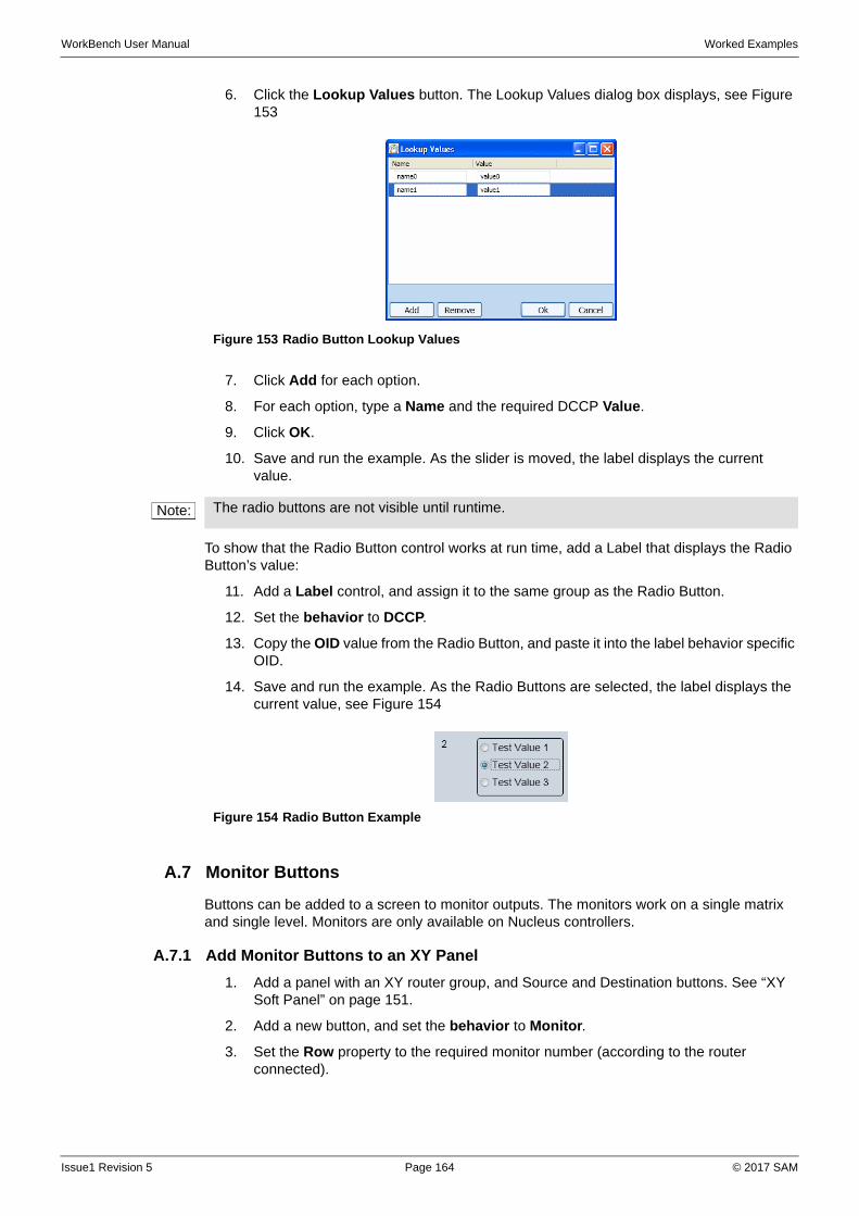
WorkBench User Manual Worked Examples
6. Click the Lookup Values button. The Lookup Values dialog box displays, see Figure 153
7. Click Add for each option.
8. For each option, type a Name and the required DCCP Value.
9. Click OK.
10. Save and run the example. As the slider is moved, the label displays the current value.
To show that the Radio Button control works at run time, add a Label that displays the Radio Button’s value:
11. Add a Label control, and assign it to the same group as the Radio Button.
12. Set the behavior to DCCP.
13. Copy the OID value from the Radio Button, and paste it into the label behavior specific OID.
14. Save and run the example. As the Radio Buttons are selected, the label displays the current value, see Figure 154
A.7 Monitor Buttons
Buttons can be added to a screen to monitor outputs. The monitors work on a single matrix and single level. Monitors are only available on Nucleus controllers.
A.7.1 Add Monitor Buttons to an XY Panel
1. Add a panel with an XY router group, and Source and Destination buttons. See “XY Soft Panel” on page 151.
2. Add a new button, and set the behavior to Monitor.
3. Set the Row property to the required monitor number (according to the router connected).
Figure 153 Radio Button Lookup Values
Note: The radio buttons are not visible until runtime.
Figure 154 Radio Button Example
Issue1 Revision 5 Page 164 © 2017 SAM
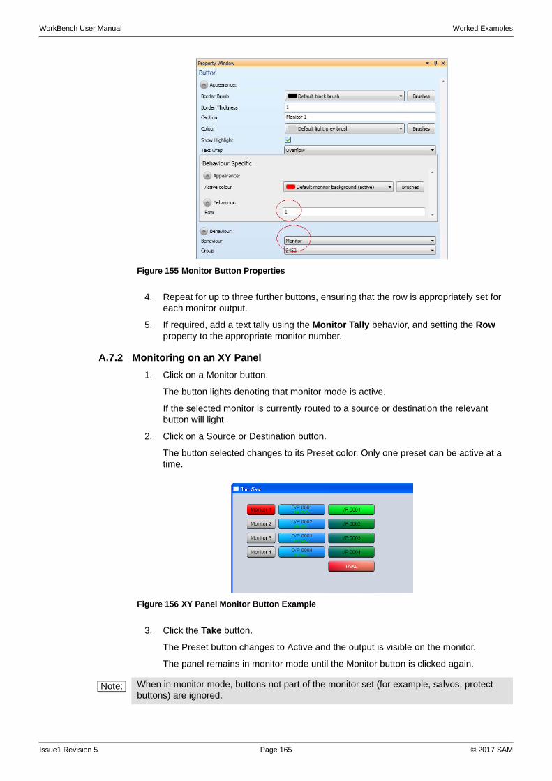
WorkBench User Manual Worked Examples
4. Repeat for up to three further buttons, ensuring that the row is appropriately set for each monitor output.
5. If required, add a text tally using the Monitor Tally behavior, and setting the Row property to the appropriate monitor number.
A.7.2 Monitoring on an XY Panel
1. Click on a Monitor button.
The button lights denoting that monitor mode is active.
If the selected monitor is currently routed to a source or destination the relevant button will light.
2. Click on a Source or Destination button.
The button selected changes to its Preset color. Only one preset can be active at a time.
3. Click the Take button.
The Preset button changes to Active and the output is visible on the monitor.
The panel remains in monitor mode until the Monitor button is clicked again.
Figure 155 Monitor Button Properties
Figure 156 XY Panel Monitor Button Example
Note: When in monitor mode, buttons not part of the monitor set (for example, salvos, protect buttons) are ignored.
Issue1 Revision 5 Page 165 © 2017 SAM
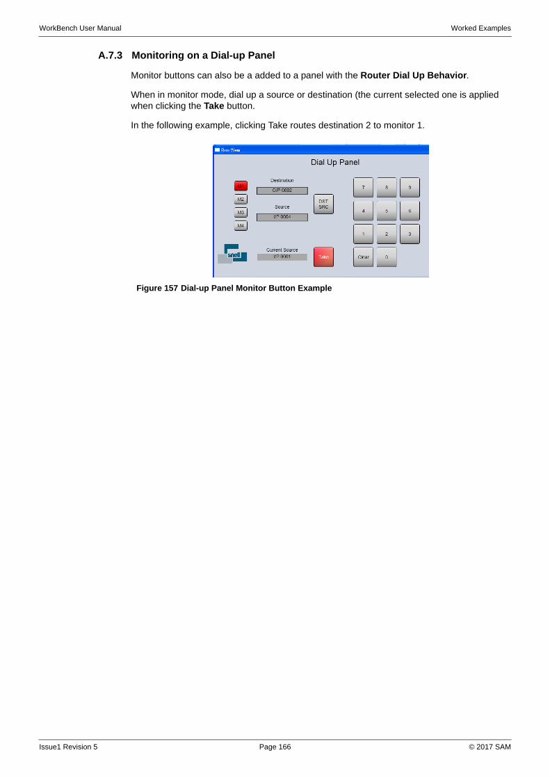
WorkBench User Manual Worked Examples
A.7.3 Monitoring on a Dial-up Panel
Monitor buttons can also be a added to a panel with the Router Dial Up Behavior.
When in monitor mode, dial up a source or destination (the current selected one is applied when clicking the Take button.
In the following example, clicking Take routes destination 2 to monitor 1.
Figure 157 Dial-up Panel Monitor Button Example
Issue1 Revision 5 Page 166 © 2017 SAM
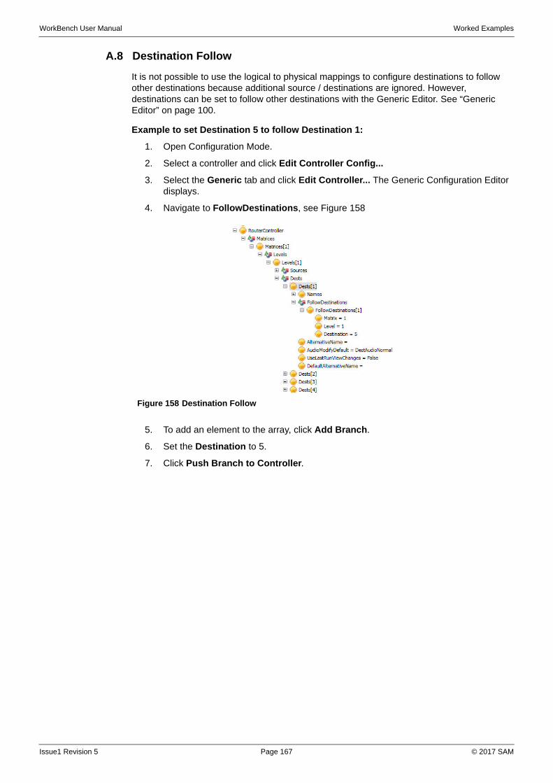
WorkBench User Manual Worked Examples
A.8 Destination Follow
It is not possible to use the logical to physical mappings to configure destinations to follow other destinations because additional source / destinations are ignored. However, destinations can be set to follow other destinations with the Generic Editor. See “Generic Editor” on page 100.
Example to set Destination 5 to follow Destination 1:
1. Open Configuration Mode.
2. Select a controller and click Edit Controller Config...
3. Select the Generic tab and click Edit Controller... The Generic Configuration Editor displays.
4. Navigate to FollowDestinations, see Figure 158
5. To add an element to the array, click Add Branch.
6. Set the Destination to 5.
7. Click Push Branch to Controller.
Figure 158 Destination Follow
Issue1 Revision 5 Page 167 © 2017 SAM
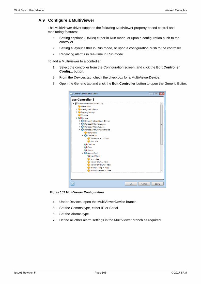
WorkBench User Manual Worked Examples
A.9 Configure a MultiViewer
The MultiViewer driver supports the following MultiViewer property-based control and monitoring features:
• Setting captions (UMDs) either in Run mode, or upon a configuration push to the controller.
• Setting a layout either in Run mode, or upon a configuration push to the controller.
• Receiving alarms in real-time in Run mode.
To add a MultiViewer to a controller:
1. Select the controller from the Configuration screen, and click the Edit Controller Config... button.
2. From the Devices tab, check the checkbox for a MultiViewerDevice.
3. Open the Generic tab and click the Edit Controller button to open the Generic Editor.
4. Under Devices, open the MultiViewerDevice branch.
5. Set the Comms type, either IP or Serial.
6. Set the Alarms type.
7. Define all other alarm settings in the MultiViewer branch as required.
Figure 159 MultiViewer Configuration
Issue1 Revision 5 Page 168 © 2017 SAM
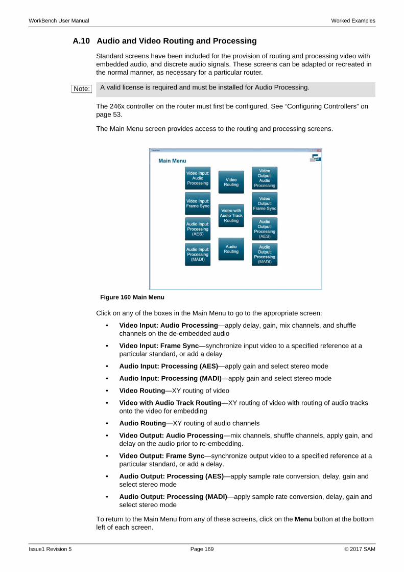
WorkBench User Manual Worked Examples
A.10 Audio and Video Routing and Processing
Standard screens have been included for the provision of routing and processing video with embedded audio, and discrete audio signals. These screens can be adapted or recreated in the normal manner, as necessary for a particular router.
The 246x controller on the router must first be configured. See “Configuring Controllers” on page 53.
The Main Menu screen provides access to the routing and processing screens.
Click on any of the boxes in the Main Menu to go to the appropriate screen:
• Video Input: Audio Processing—apply delay, gain, mix channels, and shuffle channels on the de-embedded audio
• Video Input: Frame Sync—synchronize input video to a specified reference at a particular standard, or add a delay
• Audio Input: Processing (AES)—apply gain and select stereo mode
• Audio Input: Processing (MADI)—apply gain and select stereo mode
• Video Routing—XY routing of video
• Video with Audio Track Routing—XY routing of video with routing of audio tracks onto the video for embedding
• Audio Routing—XY routing of audio channels
• Video Output: Audio Processing—mix channels, shuffle channels, apply gain, and delay on the audio prior to re-embedding.
• Video Output: Frame Sync—synchronize output video to a specified reference at a particular standard, or add a delay.
• Audio Output: Processing (AES)—apply sample rate conversion, delay, gain and select stereo mode
• Audio Output: Processing (MADI)—apply sample rate conversion, delay, gain and select stereo mode
To return to the Main Menu from any of these screens, click on the Menu button at the bottom left of each screen.
Note: A valid license is required and must be installed for Audio Processing.
Figure 160 Main Menu
Issue1 Revision 5 Page 169 © 2017 SAM
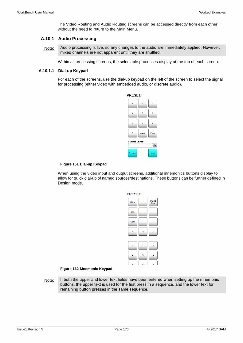
WorkBench User Manual Worked Examples
The Video Routing and Audio Routing screens can be accessed directly from each other without the need to return to the Main Menu.
A.10.1 Audio Processing
Within all processing screens, the selectable processes display at the top of each screen.
A.10.1.1 Dial-up Keypad
For each of the screens, use the dial-up keypad on the left of the screen to select the signal for processing (either video with embedded audio, or discrete audio).
When using the video input and output screens, additional mnemonics buttons display to allow for quick dial-up of named sources/destinations. These buttons can be further defined in Design mode.
Note: Audio processing is live, so any changes to the audio are immediately applied. However, mixed channels are not apparent until they are shuffled.
Figure 161 Dial-up Keypad
Figure 162 Mnemonic Keypad
Note: If both the upper and lower text fields have been entered when setting up the mnemonic buttons, the upper text is used for the first press in a sequence, and the lower text for remaining button presses in the same sequence.
Issue1 Revision 5 Page 170 © 2017 SAM
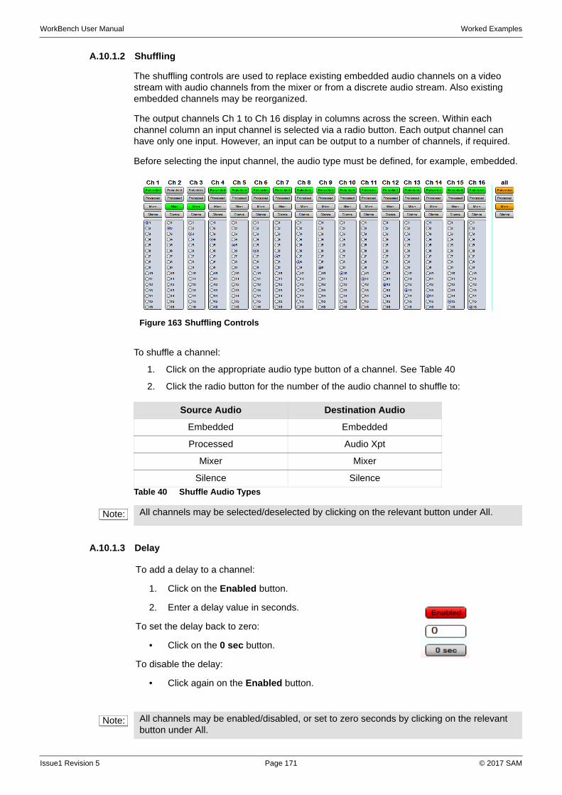
WorkBench User Manual Worked Examples
A.10.1.2 Shuffling
The shuffling controls are used to replace existing embedded audio channels on a video stream with audio channels from the mixer or from a discrete audio stream. Also existing embedded channels may be reorganized.
The output channels Ch 1 to Ch 16 display in columns across the screen. Within each channel column an input channel is selected via a radio button. Each output channel can have only one input. However, an input can be output to a number of channels, if required.
Before selecting the input channel, the audio type must be defined, for example, embedded.
To shuffle a channel:
1. Click on the appropriate audio type button of a channel. See Table 40
2. Click the radio button for the number of the audio channel to shuffle to:
A.10.1.3 Delay
Figure 163 Shuffling Controls
Source Audio Destination Audio
Embedded Embedded
Processed Audio Xpt
Mixer Mixer
Silence Silence
Table 40 Shuffle Audio Types
Note: All channels may be selected/deselected by clicking on the relevant button under All.
To add a delay to a channel:
1. Click on the Enabled button.
2. Enter a delay value in seconds.
To set the delay back to zero:
• Click on the 0 sec button.
To disable the delay:
• Click again on the Enabled button.
Note: All channels may be enabled/disabled, or set to zero seconds by clicking on the relevant button under All.
Issue1 Revision 5 Page 171 © 2017 SAM
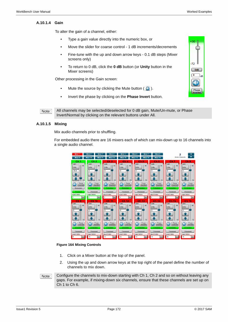
WorkBench User Manual Worked Examples
A.10.1.4 Gain
A.10.1.5 Mixing
Mix audio channels prior to shuffling.
For embedded audio there are 16 mixers each of which can mix-down up to 16 channels into a single audio channel.
1. Click on a Mixer button at the top of the panel.
2. Using the up and down arrow keys at the top right of the panel define the number of channels to mix down.
To alter the gain of a channel, either:
• Type a gain value directly into the numeric box, or
• Move the slider for coarse control - 1 dB increments/decrements
• Fine-tune with the up and down arrow keys - 0.1 dB steps (Mixer screens only)
• To return to 0 dB, click the 0 dB button (or Unity button in the Mixer screens)
Other processing in the Gain screen:
• Mute the source by clicking the Mute button ( ).
• Invert the phase by clicking on the Phase Invert button.
Note: All channels may be selected/deselected for 0 dB gain, Mute/Un-mute, or Phase Invert/Normal by clicking on the relevant buttons under All.
Figure 164 Mixing Controls
Note: Configure the channels to mix-down starting with Ch 1, Ch 2 and so on without leaving any gaps. For example, if mixing-down six channels, ensure that these channels are set up on Ch 1 to Ch 6.
Issue1 Revision 5 Page 172 © 2017 SAM
WorkBench User Manual Worked Examples
3. Click the appropriate button to set where the audio source is coming from. See Table 41
4. Set the channel number in the Input Index box, and click Set.
5. If required, apply processing to each of the channels in the same way as in the Gain screen. See “Gain” on page 172.
A.10.1.6 Stereo Mode
For AES and MADI inputs and outputs, the stereo pairings can be adjustment using the relevant buttons on the audio processing screen:
A.10.1.7 Sample Rate Conversion
Sample Rate Conversion (SRC) allows the sample rate of audio from the audio crosspoint to be converted to a different sample rate either, asynchronously, or synchronously to an input reference.
For example, sample rate conversion might be used when audio has been recorded on Mini Disc at 44.1 kHz and it needs to be converted to 48 kHz for broadcast.
SRC Setup
1. Select the SRC Rate from the drop-down list.
2. Select the SRC Reference from the drop-down list, if required.
The reference can be any of the video references or an AES reference.
3. Check the SRC Enable checkbox.
4. Check the Use SRC checkbox. On AES audio screens check the appropriate Use SRC checkboxes for each of the appropriate stereo audio pairs.
SRC Operation
• AES - Sample rate conversion is applied to groups of eight audio pairs rather than individual channels. All selected pairs in the group will be synchronous to each other and output at the same selected sample rate. Deselected pairs will pass through with their sample rates unchanged.
• MADI - Sample rate conversion is applied to all pairs in the MADI output stream rather than individual channels. All pairs in the MADI stream will be synchronous to each other and output at the same selected sample rate.
Source Audio Destination Audio
Embedded Embedded
Processed (Gain applied) Audio Xpt
Off
Table 41 Mixer Audio Types
LR Swap Swap the left and right channels of a stereo pair
Left Both The left channel of a stereo pair is duplicated for both channels
Right Both The right channel of a stereo pair is duplicated for both channels
Mono Mix The two channels are mixed down to a mono channel
Normal Standard left and right channel pairing
Note: A separate valid license is required and must be installed for Sample Rate Conversion.
Issue1 Revision 5 Page 173 © 2017 SAM
WorkBench User Manual Worked Examples
• Channels within a pair must be the same initial sample rate and synchronous to each other. If they are asynchronous to each other then sample drop or repeat is used on the right channel to match the left channel.
• Pairs within an AES group or MADI output stream can be asynchronous to each other and can be different sample rates to each other when they enter the sample rate conversion process.
• The output from the sample rate conversion can be locked to the AES reference input or one of the four physical video reference inputs.
• If no reference signal is present on the selected reference input, all the SRCs on output using that reference input will be free running and locked together. They will not be locked to the free running SRCs on the other outputs that are using the same reference.
Dolby Signals
• Dolby signals must be routed as a synchronous AES pair. The Dolby signal will automatically bypass the SRC even if the pair is selected for sample rate conversion. Any reference locking is achieved by dropping or repeating Null samples in the guard band.
Reference lock only mode
• A group of pairs or a MADI stream can be locked to the AES reference or one of the four physical video reference inputs without sample rate conversion being enabled.
• If no reference signal is present on the selected reference input, all the SRCs on output using that reference input will be free running and locked together. They will not be locked to the free running SRCs on the other outputs that are using the same reference.
SRC straight through mode
• If an AES pair doesn't have sample rate conversion enabled and doesn’t have a reference selected then that pair will be output at the same sample rate as the left channel of each pair. In the case of a MADI stream all of the pairs will be output at the same sample rate as the first active channel of the MADI stream. For example, this method can be used to pass Varispeed MADI.
Note: AES - If channels within a pair are asynchronous to each other then sample drop or repeat is used on the right channel to match the left channel.
MADI - If channels from the audio crosspoint are asynchronous to each other then sample drop or repeat is used on all channels to match the first active channel in the MADI stream.
Note: The maximum sample rate that can be input to the SRC in straight through mode is 50 kHz.
AES - If channels within a pair are asynchronous to each other then sample drop or repeat is used on the right channel to match the left channel.
MADI - If channels from the audio crosspoint are asynchronous to each other then sample drop or repeat is used on all channels to match the first active channel in the MADI stream.
Issue1 Revision 5 Page 174 © 2017 SAM
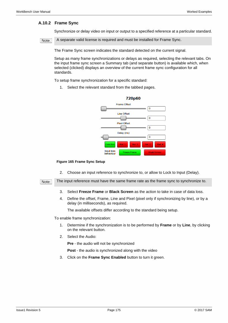
WorkBench User Manual Worked Examples
A.10.2 Frame Sync
Synchronize or delay video on input or output to a specified reference at a particular standard.
The Frame Sync screen indicates the standard detected on the current signal.
Setup as many frame synchronizations or delays as required, selecting the relevant tabs. On the input frame sync screen a Summary tab (and separate button) is available which, when selected (clicked) displays an overview of the current frame sync configuration for all standards.
To setup frame synchronization for a specific standard:
1. Select the relevant standard from the tabbed pages.
2. Choose an input reference to synchronize to, or allow to Lock to Input (Delay).
3. Select Freeze Frame or Black Screen as the action to take in case of data loss.
4. Define the offset, Frame, Line and Pixel (pixel only if synchronizing by line), or by a delay (in milliseconds), as required.
The available offsets differ according to the standard being setup.
To enable frame synchronization:
1. Determine if the synchronization is to be performed by Frame or by Line, by clicking on the relevant button.
2. Select the Audio:
Pre - the audio will not be synchronized
Post - the audio is synchronized along with the video
3. Click on the Frame Sync Enabled button to turn it green.
Note: A separate valid license is required and must be installed for Frame Sync.
Figure 165 Frame Sync Setup
Note: The input reference must have the same frame rate as the frame sync to synchronize to.
Issue1 Revision 5 Page 175 © 2017 SAM
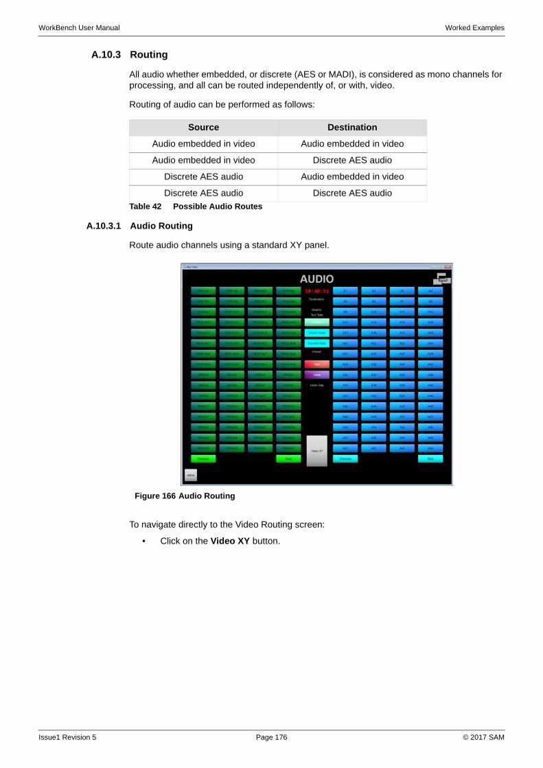
WorkBench User Manual Worked Examples
A.10.3 Routing
All audio whether embedded, or discrete (AES or MADI), is considered as mono channels for processing, and all can be routed independently of, or with, video.
Routing of audio can be performed as follows:
A.10.3.1 Audio Routing
Route audio channels using a standard XY panel.
To navigate directly to the Video Routing screen:
• Click on the Video XY button.
Source Destination
Audio embedded in video Audio embedded in video
Audio embedded in video Discrete AES audio
Discrete AES audio Audio embedded in video
Discrete AES audio Discrete AES audio
Table 42 Possible Audio Routes
Figure 166 Audio Routing
Issue1 Revision 5 Page 176 © 2017 SAM
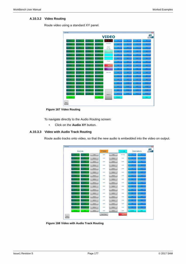
WorkBench User Manual Worked Examples
A.10.3.2 Video Routing
Route video using a standard XY panel.
To navigate directly to the Audio Routing screen:
• Click on the Audio XY button.
A.10.3.3 Video with Audio Track Routing
Route audio tracks onto video, so that the new audio is embedded into the video on output.
Figure 167 Video Routing
Figure 168 Video with Audio Track Routing
Issue1 Revision 5 Page 177 © 2017 SAM
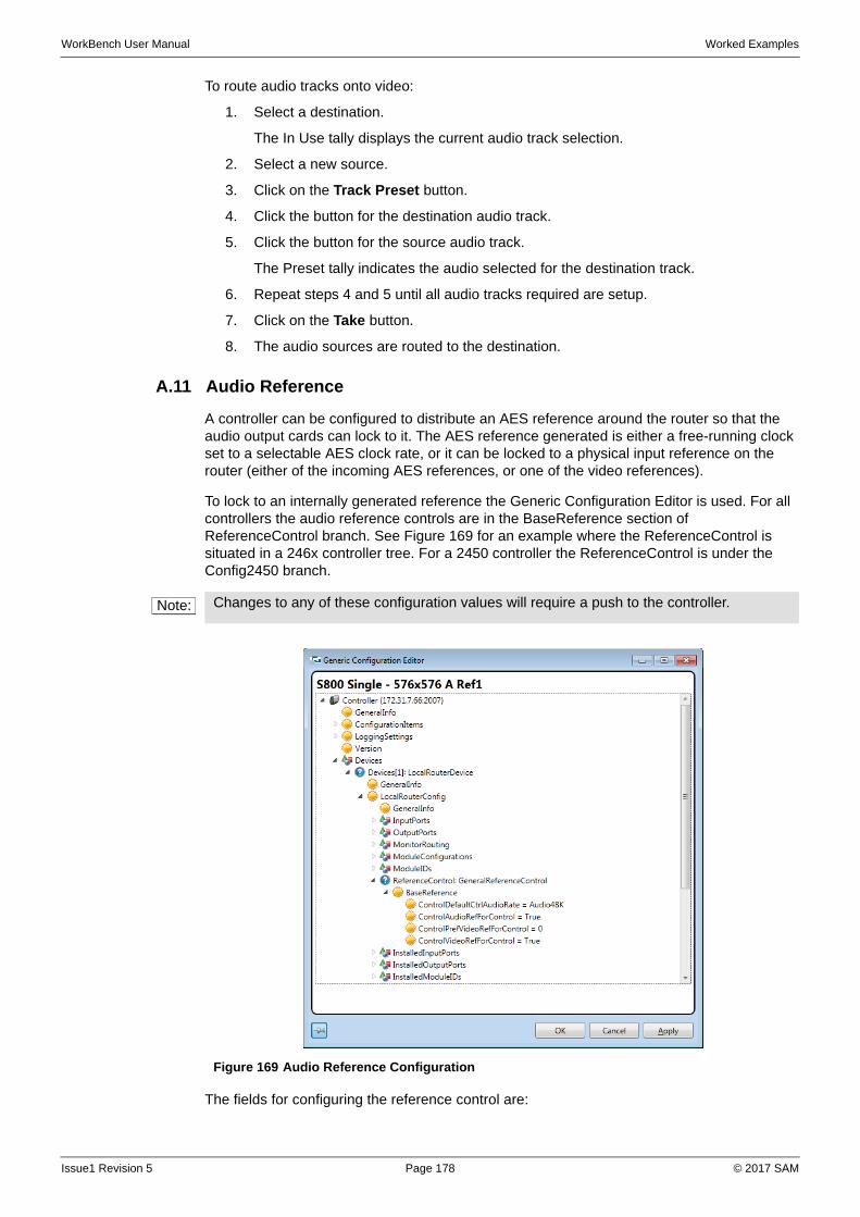
WorkBench User Manual Worked Examples
To route audio tracks onto video:
1. Select a destination.
The In Use tally displays the current audio track selection.
2. Select a new source.
3. Click on the Track Preset button.
4. Click the button for the destination audio track.
5. Click the button for the source audio track.
The Preset tally indicates the audio selected for the destination track.
6. Repeat steps 4 and 5 until all audio tracks required are setup.
7. Click on the Take button.
8. The audio sources are routed to the destination.
A.11 Audio Reference
A controller can be configured to distribute an AES reference around the router so that the audio output cards can lock to it. The AES reference generated is either a free-running clock set to a selectable AES clock rate, or it can be locked to a physical input reference on the router (either of the incoming AES references, or one of the video references).
To lock to an internally generated reference the Generic Configuration Editor is used. For all controllers the audio reference controls are in the BaseReference section of ReferenceControl branch. See Figure 169 for an example where the ReferenceControl is situated in a 246x controller tree. For a 2450 controller the ReferenceControl is under the Config2450 branch.
The fields for configuring the reference control are:
Note: Changes to any of these configuration values will require a push to the controller.
Figure 169 Audio Reference Configuration
Issue1 Revision 5 Page 178 © 2017 SAM
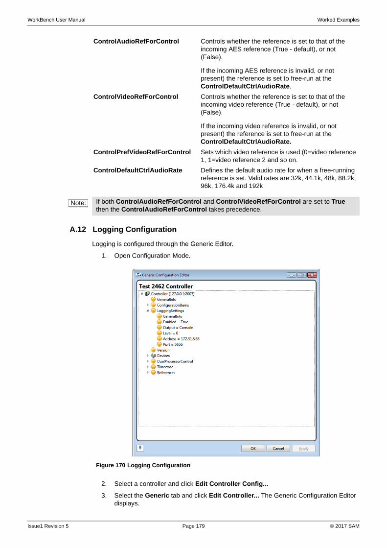
WorkBench User Manual Worked Examples
A.12 Logging Configuration
Logging is configured through the Generic Editor.
1. Open Configuration Mode.
2. Select a controller and click Edit Controller Config...
3. Select the Generic tab and click Edit Controller... The Generic Configuration Editor displays.
ControlAudioRefForControl Controls whether the reference is set to that of the incoming AES reference (True - default), or not (False).
If the incoming AES reference is invalid, or not present) the reference is set to free-run at the ControlDefaultCtrlAudioRate.
ControlVideoRefForControl Controls whether the reference is set to that of the incoming video reference (True - default), or not (False).
If the incoming video reference is invalid, or not present) the reference is set to free-run at the ControlDefaultCtrlAudioRate.
ControlPrefVideoRefForControl Sets which video reference is used (0=video reference 1, 1=video reference 2 and so on.
ControlDefaultCtrlAudioRate Defines the default audio rate for when a free-running reference is set. Valid rates are 32k, 44.1k, 48k, 88.2k, 96k, 176.4k and 192k
Note: If both ControlAudioRefForControl and ControlVideoRefForControl are set to True then the ControlAudioRefForControl takes precedence.
Figure 170 Logging Configuration
Issue1 Revision 5 Page 179 © 2017 SAM
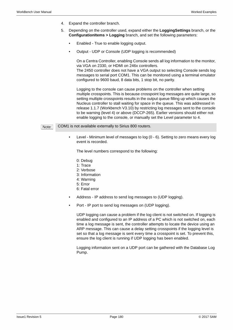
WorkBench User Manual Worked Examples
4. Expand the controller branch.
5. Depending on the controller used, expand either the LoggingSettings branch, or the ConfigurationItems > Logging branch, and set the following parameters:
• Enabled - True to enable logging output.
• Output - UDP or Console (UDP logging is recommended)
On a Centra Controller, enabling Console sends all log information to the monitor, via VGA on 2330, or HDMI on 246x controllers.The 2450 controller does not have a VGA output so selecting Console sends log messages to serial port COM1. This can be monitored using a terminal emulator configured to 9600 baud, 8 data bits, 1 stop bit, no parity.
Logging to the console can cause problems on the controller when setting multiple crosspoints. This is because crosspoint log messages are quite large, so setting multiple crosspoints results in the output queue filling up which causes the Nucleus controller to stall waiting for space in the queue. This was addressed in release 1.1.7 (Workbench V3.10) by restricting log messages sent to the console to be warning (level 4) or above (DCCP-265). Earlier versions should either not enable logging to the console, or manually set the Level parameter to 4.
• Level - Minimum level of messages to log (0 - 6). Setting to zero means every log event is recorded.
The level numbers correspond to the following:
0: Debug1: Trace2: Verbose3: Information4: Warning5: Error6: Fatal error
• Address - IP address to send log messages to (UDP logging).
• Port - IP port to send log messages on (UDP logging).
UDP logging can cause a problem if the log client is not switched on. If logging is enabled and configured to an IP address of a PC which is not switched on, each time a log message is sent, the controller attempts to locate the device using an ARP message. This can cause a delay setting crosspoints if the logging level is set so that a log message is sent every time a crosspoint is set. To prevent this, ensure the log client is running if UDP logging has been enabled.
Logging information sent on a UDP port can be gathered with the Database Log Pump.
Note: COM1 is not available externally to Sirius 800 routers.
Issue1 Revision 5 Page 180 © 2017 SAM
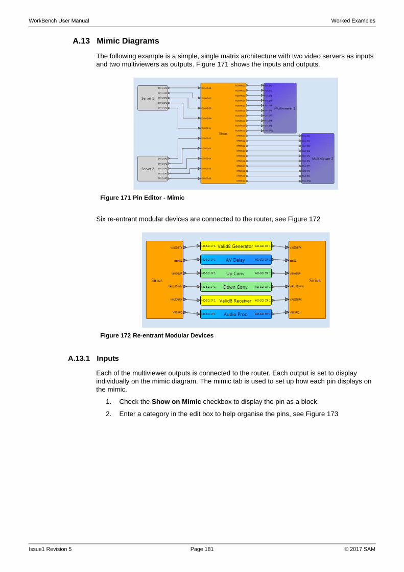
WorkBench User Manual Worked Examples
A.13 Mimic Diagrams
The following example is a simple, single matrix architecture with two video servers as inputs and two multiviewers as outputs. Figure 171 shows the inputs and outputs.
Six re-entrant modular devices are connected to the router, see Figure 172
A.13.1 Inputs
Each of the multiviewer outputs is connected to the router. Each output is set to display individually on the mimic diagram. The mimic tab is used to set up how each pin displays on the mimic.
1. Check the Show on Mimic checkbox to display the pin as a block.
2. Enter a category in the edit box to help organise the pins, see Figure 173
Figure 171 Pin Editor - Mimic
Figure 172 Re-entrant Modular Devices
Issue1 Revision 5 Page 181 © 2017 SAM
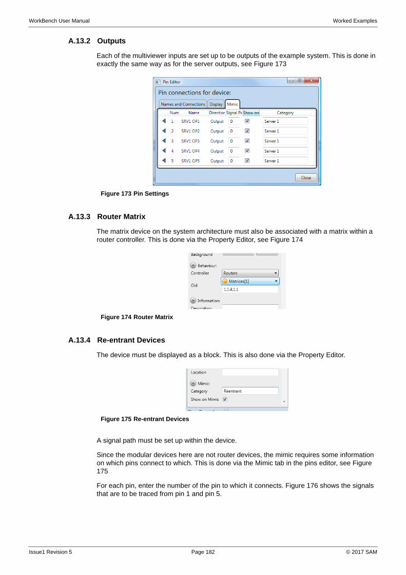
WorkBench User Manual Worked Examples
A.13.2 Outputs
Each of the multiviewer inputs are set up to be outputs of the example system. This is done in exactly the same way as for the server outputs, see Figure 173
A.13.3 Router Matrix
The matrix device on the system architecture must also be associated with a matrix within a router controller. This is done via the Property Editor, see Figure 174
A.13.4 Re-entrant Devices
The device must be displayed as a block. This is also done via the Property Editor.
A signal path must be set up within the device.
Since the modular devices here are not router devices, the mimic requires some information on which pins connect to which. This is done via the Mimic tab in the pins editor, see Figure 175
For each pin, enter the number of the pin to which it connects. Figure 176 shows the signals that are to be traced from pin 1 and pin 5.
Figure 173 Pin Settings
Figure 174 Router Matrix
Figure 175 Re-entrant Devices
Issue1 Revision 5 Page 182 © 2017 SAM
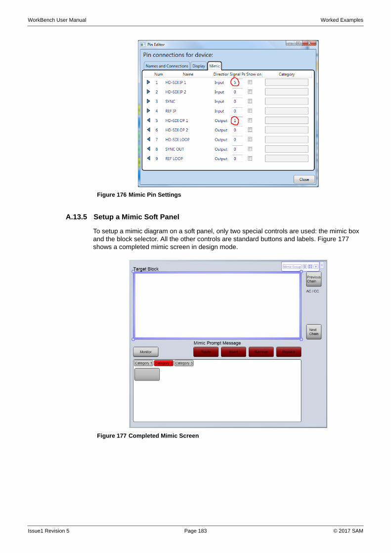
WorkBench User Manual Worked Examples
A.13.5 Setup a Mimic Soft Panel
To setup a mimic diagram on a soft panel, only two special controls are used: the mimic box and the block selector. All the other controls are standard buttons and labels. Figure 177 shows a completed mimic screen in design mode.
Figure 176 Mimic Pin Settings
Figure 177 Completed Mimic Screen
Issue1 Revision 5 Page 183 © 2017 SAM

WorkBench User Manual Worked Examples
To set up a basic mimic panel:
1. Create a new panel.
2. Create a group and set the group behavior to Mimic Behavior.
3. Set up the group behavior by assigning a tie-lines controller and choosing a monitoring device and input.
4. Add a Mimic box to the panel, ensure it is in the correct group and set the behavior to Mimic Box. Various display options are available in the property editor for this control.
5. Add a Block Selector to the panel and set the behavior to Block Selector. Various display options are available in the Property Editor for this control.
6. Add five buttons to set the mimic mode: Monitor, Route, Insert, Remove and Replace. Set the button text and behavior as appropriate.
7. Add a text label and set the behavior to Prompt Message. This displays instructions. Alter the wording of the messages via the property editor.
8. Add a text label and set the behavior to Target Block. This displays the name of the selected target block.
9. Add buttons for Previous Chain and Next Chain and set the text and behavior properties as appropriate.
10. Add two text labels and set the behaviors to Active Chain and Chain Count. These display the number of chains discovered and the index of the currently active chain.
Setup of the mimic diagram is complete.
A.14 RollCall Screens
When a RollCall Gateway controller has been configured, a screen can be designed to control and monitor devices on the RollCall network.
1. Create a screen and add a Generic behavior group to the default panel.
2. Assign the RollCall controller as the group's controller setting.
3. Add a label to the panel.
4. Set the label's behavior to DCCP behavior.
5. Set the label's OID property to a property underneath the Frames node of the controller configuration.
6. Save the screen and run it to see the results.
Issue1 Revision 5 Page 184 © 2017 SAM
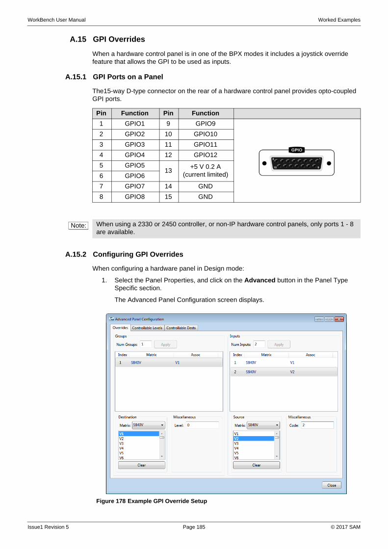
WorkBench User Manual Worked Examples
A.15 GPI Overrides
When a hardware control panel is in one of the BPX modes it includes a joystick override feature that allows the GPI to be used as inputs.
A.15.1 GPI Ports on a Panel
The15-way D-type connector on the rear of a hardware control panel provides opto-coupled GPI ports.
A.15.2 Configuring GPI Overrides
When configuring a hardware panel in Design mode:
1. Select the Panel Properties, and click on the Advanced button in the Panel Type Specific section.
The Advanced Panel Configuration screen displays.
Pin Function Pin Function
1 GPIO1 9 GPIO9
2 GPIO2 10 GPIO10
3 GPIO3 11 GPIO11
4 GPIO4 12 GPIO12
5 GPIO513
+5 V 0.2 A (current limited)6 GPIO6
7 GPIO7 14 GND
8 GPIO8 15 GND
Note: When using a 2330 or 2450 controller, or non-IP hardware control panels, only ports 1 - 8 are available.
Figure 178 Example GPI Override Setup
Issue1 Revision 5 Page 185 © 2017 SAM
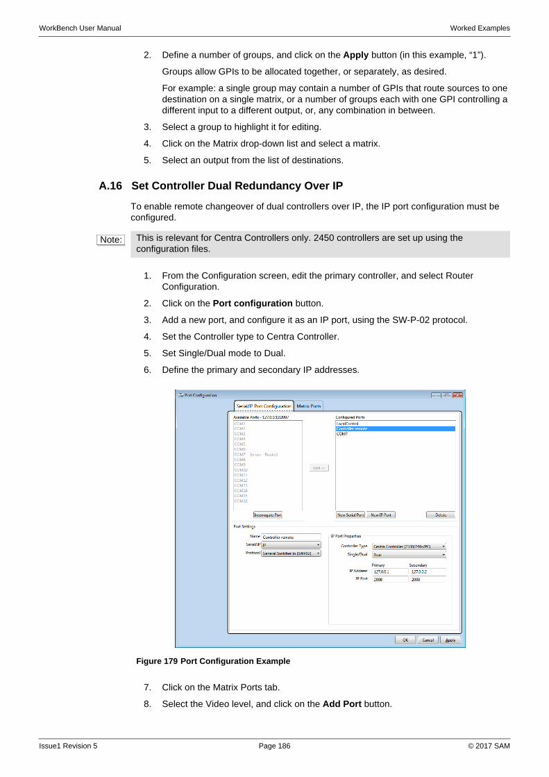
WorkBench User Manual Worked Examples
2. Define a number of groups, and click on the Apply button (in this example, “1”).
Groups allow GPIs to be allocated together, or separately, as desired.
For example: a single group may contain a number of GPIs that route sources to one destination on a single matrix, or a number of groups each with one GPI controlling a different input to a different output, or, any combination in between.
3. Select a group to highlight it for editing.
4. Click on the Matrix drop-down list and select a matrix.
5. Select an output from the list of destinations.
A.16 Set Controller Dual Redundancy Over IP
To enable remote changeover of dual controllers over IP, the IP port configuration must be configured.
1. From the Configuration screen, edit the primary controller, and select Router Configuration.
2. Click on the Port configuration button.
3. Add a new port, and configure it as an IP port, using the SW-P-02 protocol.
4. Set the Controller type to Centra Controller.
5. Set Single/Dual mode to Dual.
6. Define the primary and secondary IP addresses.
7. Click on the Matrix Ports tab.
8. Select the Video level, and click on the Add Port button.
Note: This is relevant for Centra Controllers only. 2450 controllers are set up using the configuration files.
Figure 179 Port Configuration Example
Issue1 Revision 5 Page 186 © 2017 SAM
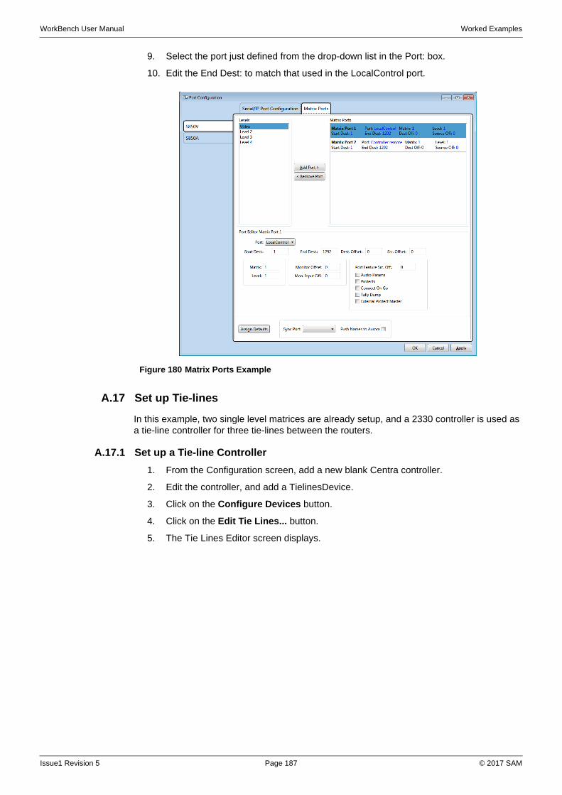
WorkBench User Manual Worked Examples
9. Select the port just defined from the drop-down list in the Port: box.
10. Edit the End Dest: to match that used in the LocalControl port.
A.17 Set up Tie-lines
In this example, two single level matrices are already setup, and a 2330 controller is used as a tie-line controller for three tie-lines between the routers.
A.17.1 Set up a Tie-line Controller
1. From the Configuration screen, add a new blank Centra controller.
2. Edit the controller, and add a TielinesDevice.
3. Click on the Configure Devices button.
4. Click on the Edit Tie Lines... button.
5. The Tie Lines Editor screen displays.
Figure 180 Matrix Ports Example
Issue1 Revision 5 Page 187 © 2017 SAM
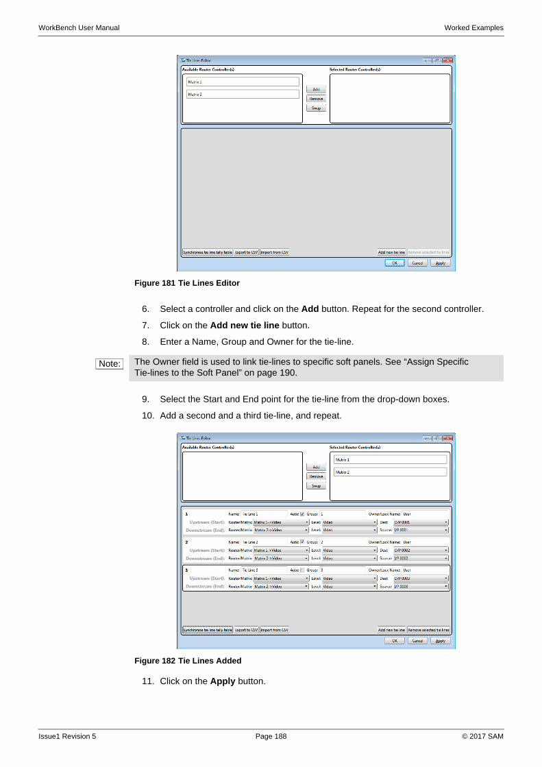
WorkBench User Manual Worked Examples
6. Select a controller and click on the Add button. Repeat for the second controller.
7. Click on the Add new tie line button.
8. Enter a Name, Group and Owner for the tie-line.
9. Select the Start and End point for the tie-line from the drop-down boxes.
10. Add a second and a third tie-line, and repeat.
11. Click on the Apply button.
Figure 181 Tie Lines Editor
Note: The Owner field is used to link tie-lines to specific soft panels. See “Assign Specific Tie-lines to the Soft Panel” on page 190.
Figure 182 Tie Lines Added
Issue1 Revision 5 Page 188 © 2017 SAM
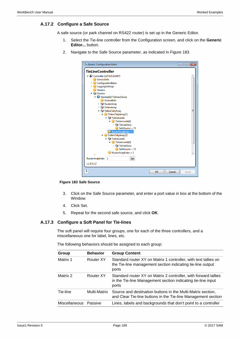
WorkBench User Manual Worked Examples
A.17.2 Configure a Safe Source
A safe source (or park channel on RS422 router) is set up in the Generic Editor.
1. Select the Tie-line controller from the Configuration screen, and click on the Generic Editor... button.
2. Navigate to the Safe Source parameter, as indicated in Figure 183
3. Click on the Safe Source parameter, and enter a port value in box at the bottom of the Window.
4. Click Set.
5. Repeat for the second safe source, and click OK.
A.17.3 Configure a Soft Panel for Tie-lines
The soft panel will require four groups, one for each of the three controllers, and a miscellaneous one for label, lines, etc.
The following behaviors should be assigned to each group:
Figure 183 Safe Source
Group Behavior Group Content
Matrix 1 Router XY Standard router XY on Matrix 1 controller, with text tallies on the Tie-line management section indicating tie-line output ports
Matrix 2 Router XY Standard router XY on Matrix 2 controller, with forward tallies in the Tie-line Management section indicating tie-line input ports
Tie-line Multi-Matrix Source and destination buttons in the Multi-Matrix section, and Clear Tie-line buttons in the Tie-line Management section
Miscellaneous Passive Lines, labels and backgrounds that don’t point to a controller
Issue1 Revision 5 Page 189 © 2017 SAM
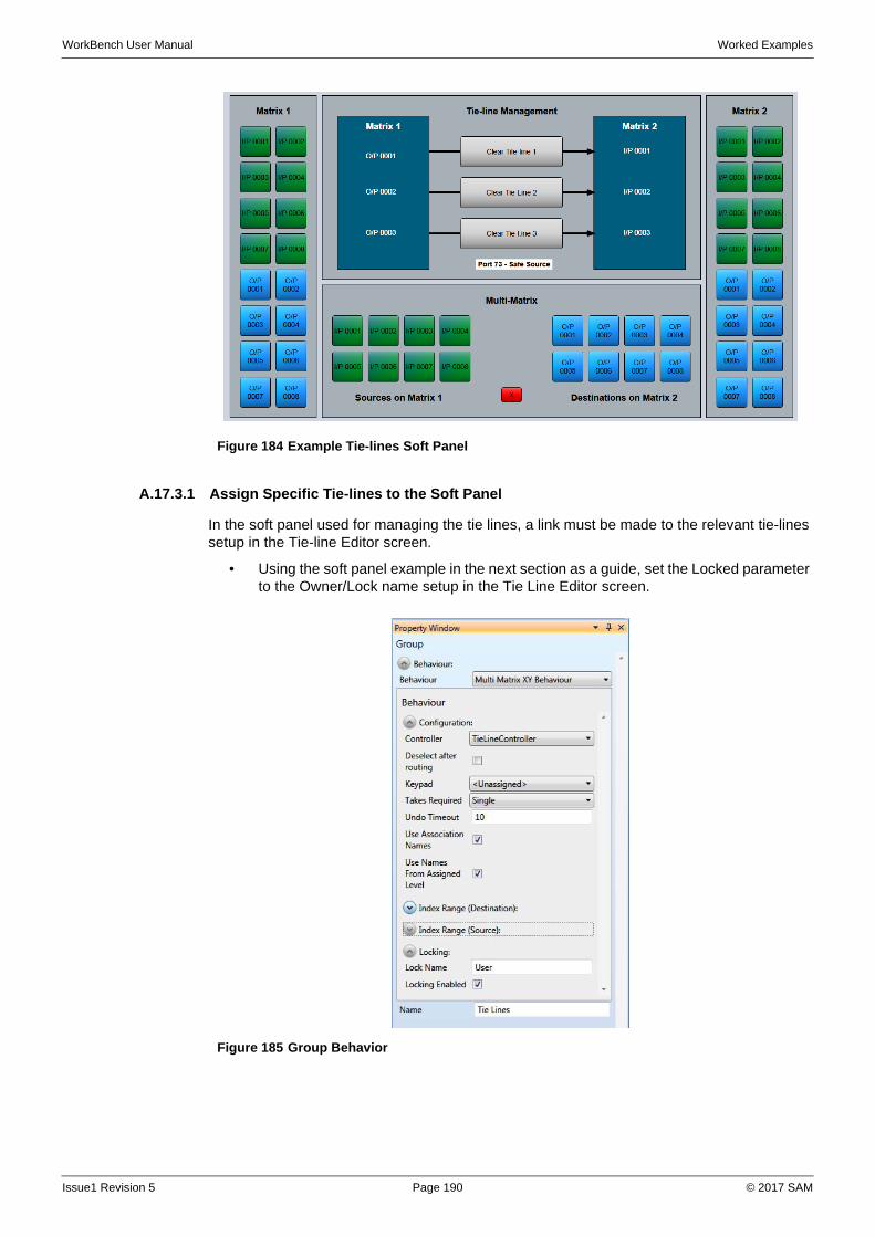
WorkBench User Manual Worked Examples
A.17.3.1 Assign Specific Tie-lines to the Soft Panel
In the soft panel used for managing the tie lines, a link must be made to the relevant tie-lines setup in the Tie-line Editor screen.
• Using the soft panel example in the next section as a guide, set the Locked parameter to the Owner/Lock name setup in the Tie Line Editor screen.
Figure 184 Example Tie-lines Soft Panel
Figure 185 Group Behavior
Issue1 Revision 5 Page 190 © 2017 SAM
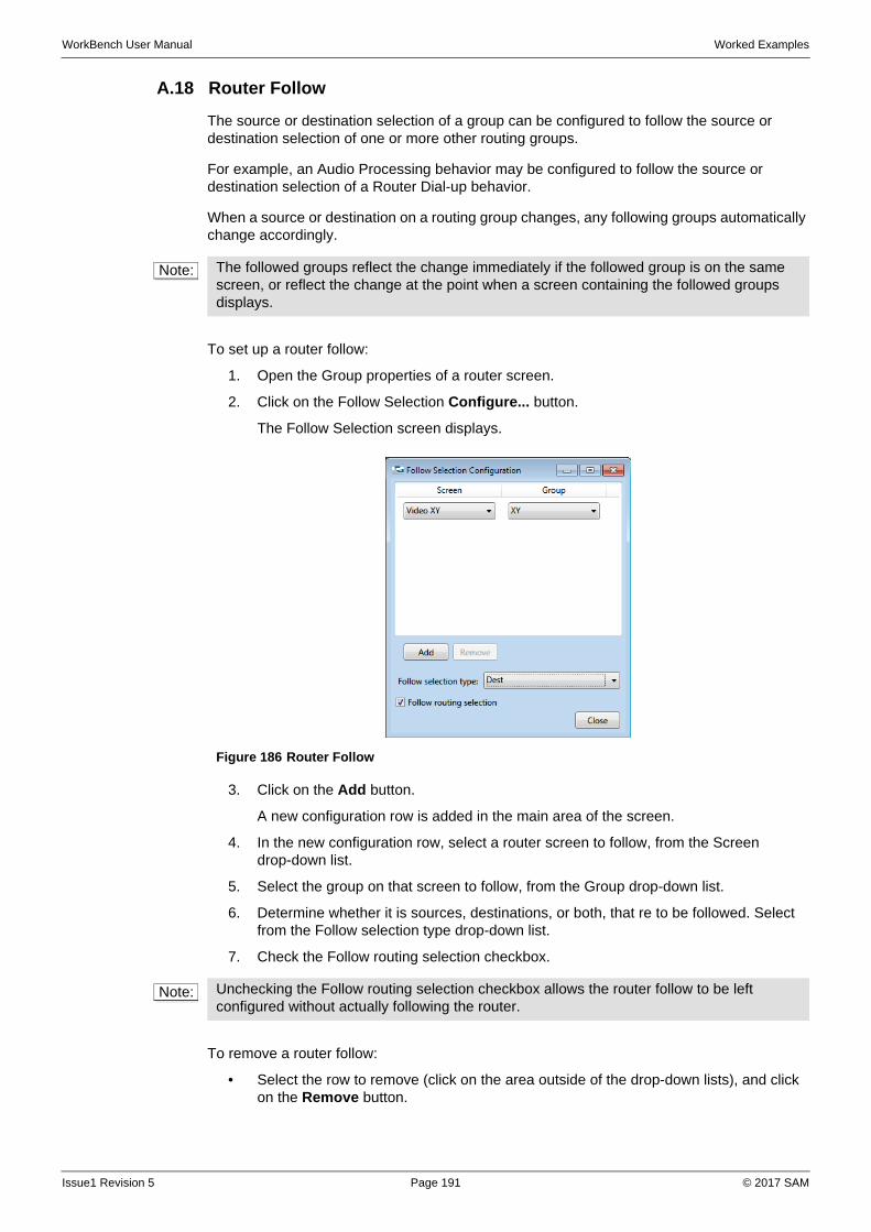
WorkBench User Manual Worked Examples
A.18 Router Follow
The source or destination selection of a group can be configured to follow the source or destination selection of one or more other routing groups.
For example, an Audio Processing behavior may be configured to follow the source or destination selection of a Router Dial-up behavior.
When a source or destination on a routing group changes, any following groups automatically change accordingly.
To set up a router follow:
1. Open the Group properties of a router screen.
2. Click on the Follow Selection Configure... button.
The Follow Selection screen displays.
3. Click on the Add button.
A new configuration row is added in the main area of the screen.
4. In the new configuration row, select a router screen to follow, from the Screen drop-down list.
5. Select the group on that screen to follow, from the Group drop-down list.
6. Determine whether it is sources, destinations, or both, that re to be followed. Select from the Follow selection type drop-down list.
7. Check the Follow routing selection checkbox.
To remove a router follow:
• Select the row to remove (click on the area outside of the drop-down lists), and click on the Remove button.
Note: The followed groups reflect the change immediately if the followed group is on the same screen, or reflect the change at the point when a screen containing the followed groups displays.
Figure 186 Router Follow
Note: Unchecking the Follow routing selection checkbox allows the router follow to be left configured without actually following the router.
Issue1 Revision 5 Page 191 © 2017 SAM
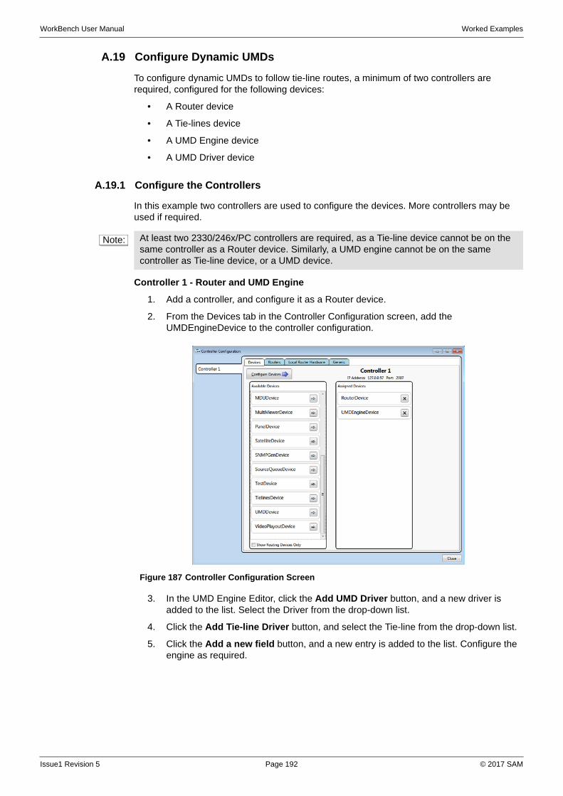
WorkBench User Manual Worked Examples
A.19 Configure Dynamic UMDs
To configure dynamic UMDs to follow tie-line routes, a minimum of two controllers are required, configured for the following devices:
• A Router device
• A Tie-lines device
• A UMD Engine device
• A UMD Driver device
A.19.1 Configure the Controllers
In this example two controllers are used to configure the devices. More controllers may be used if required.
Controller 1 - Router and UMD Engine
1. Add a controller, and configure it as a Router device.
2. From the Devices tab in the Controller Configuration screen, add the UMDEngineDevice to the controller configuration.
3. In the UMD Engine Editor, click the Add UMD Driver button, and a new driver is added to the list. Select the Driver from the drop-down list.
4. Click the Add Tie-line Driver button, and select the Tie-line from the drop-down list.
5. Click the Add a new field button, and a new entry is added to the list. Configure the engine as required.
Note: At least two 2330/246x/PC controllers are required, as a Tie-line device cannot be on the same controller as a Router device. Similarly, a UMD engine cannot be on the same controller as Tie-line device, or a UMD device.
Figure 187 Controller Configuration Screen
Issue1 Revision 5 Page 192 © 2017 SAM
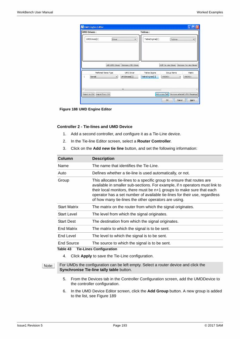
WorkBench User Manual Worked Examples
Controller 2 - Tie-lines and UMD Device
1. Add a second controller, and configure it as a Tie-Line device.
2. In the Tie-line Editor screen, select a Router Controller.
3. Click on the Add new tie line button, and set the following information:
4. Click Apply to save the Tie-Line configuration.
5. From the Devices tab in the Controller Configuration screen, add the UMDDevice to the controller configuration.
6. In the UMD Device Editor screen, click the Add Group button. A new group is added to the list, see Figure 189
Figure 188 UMD Engine Editor
Column Description
Name The name that identifies the Tie-Line.
Auto Defines whether a tie-line is used automatically, or not.
Group This allocates tie-lines to a specific group to ensure that routes are available in smaller sub-sections. For example, if n operators must link to their local monitors, there must be n+1 groups to make sure that each operator has a set number of available tie-lines for their use, regardless of how many tie-lines the other operators are using.
Start Matrix The matrix on the router from which the signal originates.
Start Level The level from which the signal originates.
Start Dest The destination from which the signal originates.
End Matrix The matrix to which the signal is to be sent.
End Level The level to which the signal is to be sent.
End Source The source to which the signal is to be sent.
Table 43 Tie-Lines Configuration
Note: For UMDs the configuration can be left empty. Select a router device and click the Synchronise Tie-line tally table button.
Issue1 Revision 5 Page 193 © 2017 SAM
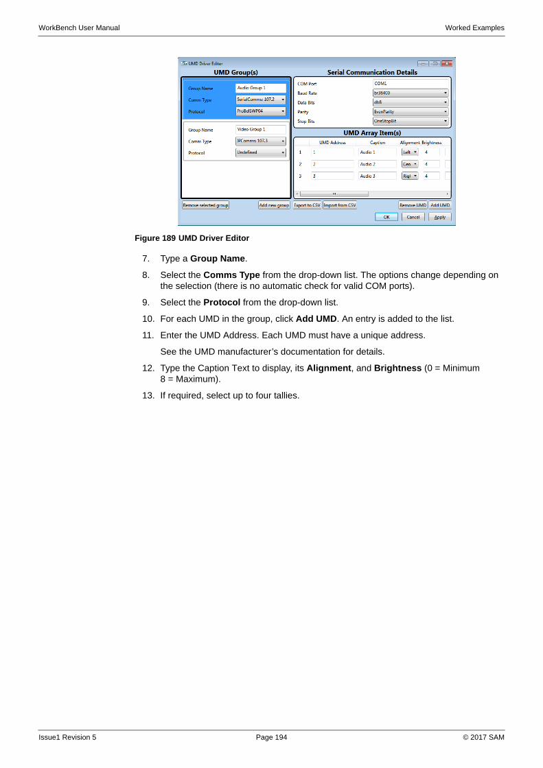
WorkBench User Manual Worked Examples
7. Type a Group Name.
8. Select the Comms Type from the drop-down list. The options change depending on the selection (there is no automatic check for valid COM ports).
9. Select the Protocol from the drop-down list.
10. For each UMD in the group, click Add UMD. An entry is added to the list.
11. Enter the UMD Address. Each UMD must have a unique address.
See the UMD manufacturer’s documentation for details.
12. Type the Caption Text to display, its Alignment, and Brightness (0 = Minimum 8 = Maximum).
13. If required, select up to four tallies.
Figure 189 UMD Driver Editor
Issue1 Revision 5 Page 194 © 2017 SAM
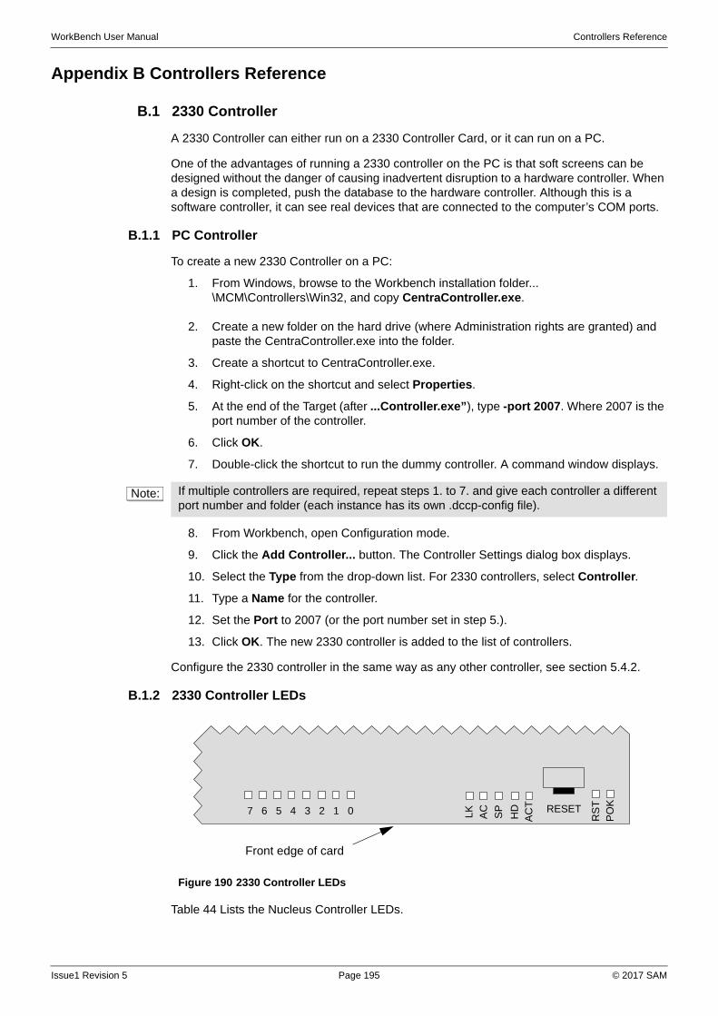
WorkBench User Manual Controllers Reference
Appendix B Controllers Reference
B.1 2330 Controller
A 2330 Controller can either run on a 2330 Controller Card, or it can run on a PC.
One of the advantages of running a 2330 controller on the PC is that soft screens can be designed without the danger of causing inadvertent disruption to a hardware controller. When a design is completed, push the database to the hardware controller. Although this is a software controller, it can see real devices that are connected to the computer’s COM ports.
B.1.1 PC Controller
To create a new 2330 Controller on a PC:
1. From Windows, browse to the Workbench installation folder... \MCM\Controllers\Win32, and copy CentraController.exe.
2. Create a new folder on the hard drive (where Administration rights are granted) and paste the CentraController.exe into the folder.
3. Create a shortcut to CentraController.exe.
4. Right-click on the shortcut and select Properties.
5. At the end of the Target (after ...Controller.exe”), type -port 2007. Where 2007 is the port number of the controller.
6. Click OK.
7. Double-click the shortcut to run the dummy controller. A command window displays.
8. From Workbench, open Configuration mode.
9. Click the Add Controller... button. The Controller Settings dialog box displays.
10. Select the Type from the drop-down list. For 2330 controllers, select Controller.
11. Type a Name for the controller.
12. Set the Port to 2007 (or the port number set in step 5.).
13. Click OK. The new 2330 controller is added to the list of controllers.
Configure the 2330 controller in the same way as any other controller, see section 5.4.2.
B.1.2 2330 Controller LEDs
Table 44 Lists the Nucleus Controller LEDs.
Note: If multiple controllers are required, repeat steps 1. to 7. and give each controller a different port number and folder (each instance has its own .dccp-config file).
Figure 190 2330 Controller LEDs
7 6 5 4 3 2 1 0 LK
AC
SP
HD
AC
T
RS
TP
OKRESET
Front edge of card
Issue1 Revision 5 Page 195 © 2017 SAM

WorkBench User Manual Controllers Reference
B.1.3 Updating 2330 Controller Cards
All 2330 cards store their configuration information on a standard CompactFlash card. The Pbak Deployment tool, which is installed along with Workbench, is used to write the required configuration information to the boot sector of the CompactFlash card.
1. Open Pbak Deploy Tool. From the Windows Start menu:
Start | All Programs | Snell | MCM | Utilities | Pbak Deploy Tool
2. From the File menu, select Configuration. The Settings dialog box displays.
3. Select the folder and drive locations.
4. Click OK.
5. In the main window, select the Pbl2330Controller.RTB, and click Write to CF.
6. When the configuration has been written to the CompactFlash card, click OK.
7. Update the config.xml file to reflect the controller’s actual IP address.
By default, the file is located in the Workbench installation folder... \MCM\PbakDeploy.
8. Save the file and copy it to the CompactFlash card.
LED Description
0 ON - Controller ActiveOFF - Controller Standby
1 ON - Watchdog enabledOFF - Watchdog disabled
2 Flashing - indicates controller running
3 Not used
4 Not used
5 Not used
6 Not used
7 Not used
POK Power OK
RST Card is being reset. Reboot follows
ACT Indicates the active card of a redundant pair
HD Hard disk activity (if fitted)
SP Not used
AC Ethernet Activity. Flickers on send/receive
LK Ethernet Link Status. Lights when activeTable 44 2330 Controller LEDs
Note: The 2330 Controller can be run as software on a PC.
Target Drive From the drop-down list, select the drive to which the CompactFlash card is attached.
RTB directory Specify the directory that contains the RTB executable file. To ensure correct operation, use the most current router RTB file available.
DAT directory The DAT directory contains configuration files required by the Morpheus Automation system. This is not relevant for Workbench.
On time tools directory
Specify the directory that contains the PbakDeploy.exe file.
Show Makedisk progress
Select this option to display progress information when writing to the CompactFlash card.
Table 45 Pbak Deploy Settings
Issue1 Revision 5 Page 196 © 2017 SAM
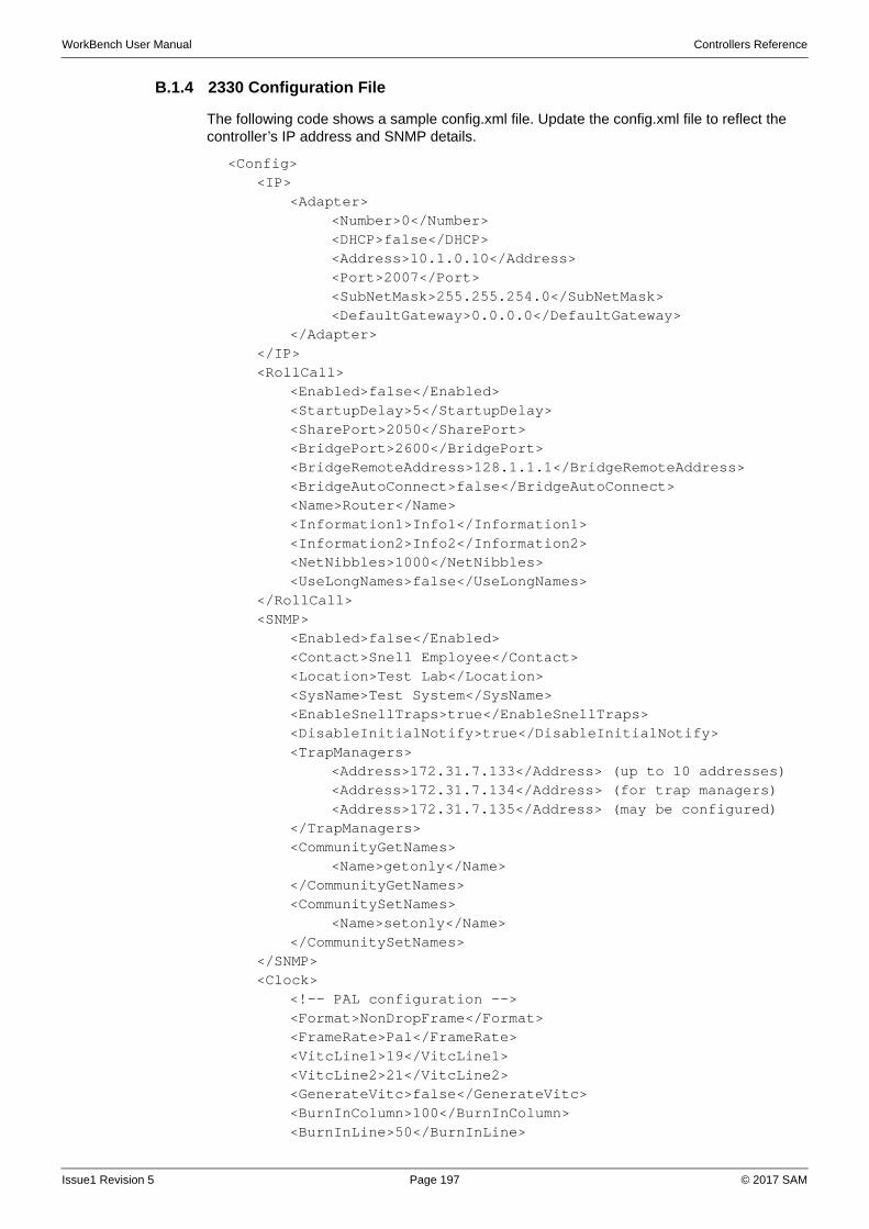
WorkBench User Manual Controllers Reference
B.1.4 2330 Configuration File
The following code shows a sample config.xml file. Update the config.xml file to reflect the controller’s IP address and SNMP details.
<Config><IP>
<Adapter><Number>0</Number><DHCP>false</DHCP><Address>10.1.0.10</Address><Port>2007</Port><SubNetMask>255.255.254.0</SubNetMask><DefaultGateway>0.0.0.0</DefaultGateway>
</Adapter></IP><RollCall>
<Enabled>false</Enabled> <StartupDelay>5</StartupDelay> <SharePort>2050</SharePort> <BridgePort>2600</BridgePort> <BridgeRemoteAddress>128.1.1.1</BridgeRemoteAddress> <BridgeAutoConnect>false</BridgeAutoConnect> <Name>Router</Name> <Information1>Info1</Information1> <Information2>Info2</Information2> <NetNibbles>1000</NetNibbles> <UseLongNames>false</UseLongNames>
</RollCall><SNMP>
<Enabled>false</Enabled><Contact>Snell Employee</Contact><Location>Test Lab</Location><SysName>Test System</SysName><EnableSnellTraps>true</EnableSnellTraps><DisableInitialNotify>true</DisableInitialNotify><TrapManagers>
<Address>172.31.7.133</Address> (up to 10 addresses)<Address>172.31.7.134</Address> (for trap managers)<Address>172.31.7.135</Address> (may be configured)
</TrapManagers><CommunityGetNames>
<Name>getonly</Name></CommunityGetNames><CommunitySetNames>
<Name>setonly</Name></CommunitySetNames>
</SNMP><Clock>
<!-- PAL configuration --><Format>NonDropFrame</Format><FrameRate>Pal</FrameRate><VitcLine1>19</VitcLine1><VitcLine2>21</VitcLine2><GenerateVitc>false</GenerateVitc><BurnInColumn>100</BurnInColumn><BurnInLine>50</BurnInLine>
Issue1 Revision 5 Page 197 © 2017 SAM
WorkBench User Manual Controllers Reference
<SyncLine>7</SyncLine></Clock>
</Config>
B.1.5 RollCall Operation
In order for RollCall to operate the relevant templates must be copied on the controller’s compact flash card. The templates are included with the Workbench installer, and deployed (by default) to the Workbench installation folder... \MCM\Controllers\RollCall Templates\2330.
In this folder, the folders “Matrix,”, “Nucleus”, and “XYPanel” are required. Optionally, the folder “WebContent” can be copied to allow web browser access to the controller.
RollCall also needs to be enabled in the config.xml file. See “2330 Configuration File” on page 197.
Note: The RollCall templates must be updated if the controller software is updated. Both are included in the Workbench installer.
Issue1 Revision 5 Page 198 © 2017 SAM
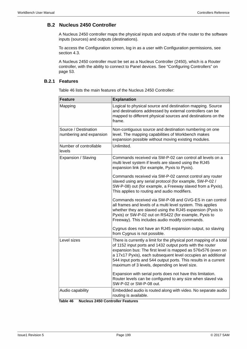
WorkBench User Manual Controllers Reference
B.2 Nucleus 2450 Controller
A Nucleus 2450 controller maps the physical inputs and outputs of the router to the software inputs (sources) and outputs (destinations).
To access the Configuration screen, log in as a user with Configuration permissions, see section 4.3.
A Nucleus 2450 controller must be set as a Nucleus Controller (2450), which is a Router controller, with the ability to connect to Panel devices. See “Configuring Controllers” on page 53.
B.2.1 Features
Table 46 lists the main features of the Nucleus 2450 Controller:
Feature Explanation
Mapping Logical to physical source and destination mapping. Source and destinations addressed by external controllers can be mapped to different physical sources and destinations on the frame.
Source / Destination numbering and expansion
Non-contiguous source and destination numbering on one level. The mapping capabilities of Workbench makes expansion possible without moving existing modules.
Number of controllable levels
Unlimited.
Expansion / Slaving Commands received via SW-P-02 can control all levels on a multi level system if levels are slaved using the RJ45 expansion link (for example, Pyxis to Pyxis).
Commands received via SW-P-02 cannot control any router slaved using any serial protocol (for example, SW-P-02 / SW-P-08) out (for example, a Freeway slaved from a Pyxis). This applies to routing and audio modifiers.
Commands received via SW-P-08 and GVG-ES in can control all frames and levels of a multi level system. This applies whether they are slaved using the RJ45 expansion (Pyxis to Pyxis) or SW-P-02 out on RS422 (for example, Pyxis to Freeway). This includes audio modify commands.
Cygnus does not have an RJ45 expansion output, so slaving from Cygnus is not possible.
Level sizes There is currently a limit for the physical port mapping of a total of 1152 input ports and 1432 output ports with the router expansion bus: The first level is mapped as 576x576 (even on a 17x17 Pyxis), each subsequent level occupies an additional 544 input ports and 544 output ports. This results in a current maximum of 3 levels, depending on level size.
Expansion with serial ports does not have this limitation. Router levels can be configured to any size when slaved via SW-P-02 or SW-P-08 out.
Audio capability Embedded audio is routed along with video. No separate audio routing is available.
Table 46 Nucleus 2450 Controller Features
Issue1 Revision 5 Page 199 © 2017 SAM
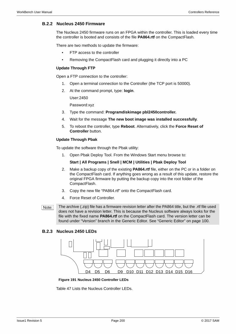
WorkBench User Manual Controllers Reference
B.2.2 Nucleus 2450 Firmware
The Nucleus 2450 firmware runs on an FPGA within the controller. This is loaded every time the controller is booted and consists of the file PA864.rtf on the CompactFlash.
There are two methods to update the firmware:
• FTP access to the controller
• Removing the CompactFlash card and plugging it directly into a PC
Update Through FTP
Open a FTP connection to the controller:
1. Open a terminal connection to the Controller (the TCP port is 50000).
2. At the command prompt, type: login.
User:2450
Password:xyz
3. Type the command: Programdiskimage pbl2450controller.
4. Wait for the message The new boot image was installed successfully.
5. To reboot the controller, type Reboot. Alternatively, click the Force Reset of Controller button.
Update Through Pbak
To update the software through the Pbak utility:
1. Open Pbak Deploy Tool. From the Windows Start menu browse to:
Start | All Programs | Snell | MCM | Utilities | Pbak Deploy Tool
2. Make a backup copy of the existing PA864.rtf file, either on the PC or in a folder on the CompactFlash card. If anything goes wrong as a result of this update, restore the original FPGA firmware by putting the backup copy into the root folder of the CompactFlash.
3. Copy the new file “PA864.rtf” onto the CompactFlash card.
4. Force Reset of Controller.
B.2.3 Nucleus 2450 LEDs
Table 47 Lists the Nucleus Controller LEDs.
Note: The archive (.zip) file has a firmware revision letter after the PA864 title, but the .rtf file used does not have a revision letter. This is because the Nucleus software always looks for the file with the fixed name PA864.rtf on the CompactFlash card. The version letter can be found under “Version” branch in the Generic Editor. See “Generic Editor” on page 100.
Figure 191 Nucleus 2450 Controller LEDs
D4 D5 D6 D9 D10 D11 D12 D13 D14 D15 D16
Issue1 Revision 5 Page 200 © 2017 SAM
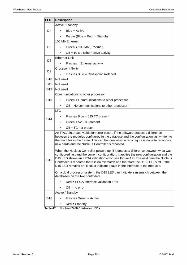
WorkBench User Manual Controllers Reference
LED Description
D4
Active / Standby
• Blue = Active
• Purple (Blue + Red) = Standby
D5
100 Mb Ethernet
• Green = 100 Mb (Ethernet)
• Off = 10 Mb Ethernet/No activity
D6Ethernet Link
• Flashes = Ethernet activity
D9Crosspoint Switch
• Flashes Blue = Crosspoint switched
D10 Not used
D11 Not used
D12 Not used
D13
Communications to other processor
• Green = Communications to other processor
• Off = No communications to other processor
D14
LTC
• Flashes Blue = 625 TC present
• Green = 525 TC present
• Off = TC not present
D15
An FPGA interface validation error occurs if the software detects a difference between the modules configured in the database and the configuration last written to the modules in the frame. This can happen when a reconfigure is done to recognise new cards and the Nucleus Controller is rebooted.
When the Nucleus Controller powers up, if it detects a difference between what was configured last and the current configuration, it applies the new configuration and the D15 LED shows an FPGA validation error, see Figure 191 The next time the Nucleus Controller is rebooted there is no mismatch and therefore the D15 LED is off. If the D15 LED remains on, it could indicate a fault in the interface to the modules.
On a dual processor system, the D15 LED can indicate a mismatch between the databases on the two controllers.
• Red = FPGA interface validation error
• Off = no error
D16
Active / Standby
• Flashes Green = Active
• Red = StandbyTable 47 Nucleus 2450 Controller LEDs
Issue1 Revision 5 Page 201 © 2017 SAM
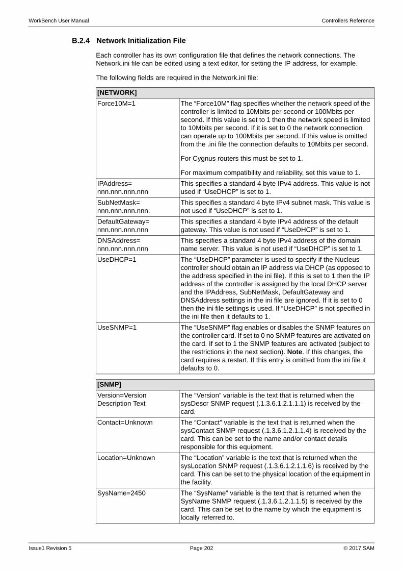
WorkBench User Manual Controllers Reference
B.2.4 Network Initialization File
Each controller has its own configuration file that defines the network connections. The Network.ini file can be edited using a text editor, for setting the IP address, for example.
The following fields are required in the Network.ini file:
[NETWORK]
Force10M=1 The “Force10M” flag specifies whether the network speed of the controller is limited to 10Mbits per second or 100Mbits per second. If this value is set to 1 then the network speed is limited to 10Mbits per second. If it is set to 0 the network connection can operate up to 100Mbits per second. If this value is omitted from the .ini file the connection defaults to 10Mbits per second.
For Cygnus routers this must be set to 1.
For maximum compatibility and reliability, set this value to 1.
IPAddress= nnn.nnn.nnn.nnn
This specifies a standard 4 byte IPv4 address. This value is not used if “UseDHCP” is set to 1.
SubNetMask= nnn.nnn.nnn.nnn.
This specifies a standard 4 byte IPv4 subnet mask. This value is not used if “UseDHCP” is set to 1.
DefaultGateway= nnn.nnn.nnn.nnn
This specifies a standard 4 byte IPv4 address of the default gateway. This value is not used if “UseDHCP” is set to 1.
DNSAddress= nnn.nnn.nnn.nnn
This specifies a standard 4 byte IPv4 address of the domain name server. This value is not used if “UseDHCP” is set to 1.
UseDHCP=1 The “UseDHCP” parameter is used to specify if the Nucleus controller should obtain an IP address via DHCP (as opposed to the address specified in the ini file). If this is set to 1 then the IP address of the controller is assigned by the local DHCP server and the IPAddress, SubNetMask, DefaultGateway and DNSAddress settings in the ini file are ignored. If it is set to 0 then the ini file settings is used. If “UseDHCP” is not specified in the ini file then it defaults to 1.
UseSNMP=1 The “UseSNMP” flag enables or disables the SNMP features on the controller card. If set to 0 no SNMP features are activated on the card. If set to 1 the SNMP features are activated (subject to the restrictions in the next section). Note. If this changes, the card requires a restart. If this entry is omitted from the ini file it defaults to 0.
[SNMP]
Version=Version Description Text
The “Version” variable is the text that is returned when the sysDescr SNMP request (.1.3.6.1.2.1.1.1) is received by the card.
Contact=Unknown The “Contact” variable is the text that is returned when the sysContact SNMP request (.1.3.6.1.2.1.1.4) is received by the card. This can be set to the name and/or contact details responsible for this equipment.
Location=Unknown The “Location” variable is the text that is returned when the sysLocation SNMP request (.1.3.6.1.2.1.1.6) is received by the card. This can be set to the physical location of the equipment in the facility.
SysName=2450 The “SysName” variable is the text that is returned when the SysName SNMP request (.1.3.6.1.2.1.1.5) is received by the card. This can be set to the name by which the equipment is locally referred to.
Issue1 Revision 5 Page 202 © 2017 SAM
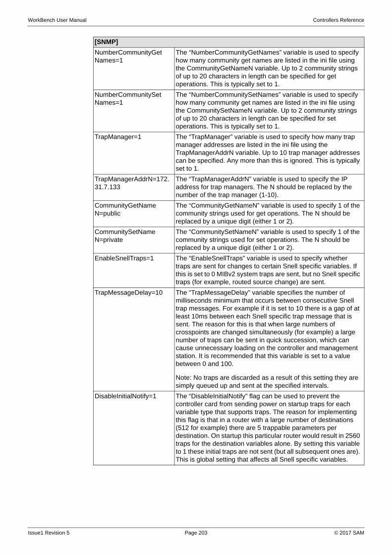
WorkBench User Manual Controllers Reference
NumberCommunityGetNames=1
The “NumberCommunityGetNames” variable is used to specify how many community get names are listed in the ini file using the CommunityGetNameN variable. Up to 2 community strings of up to 20 characters in length can be specified for get operations. This is typically set to 1.
NumberCommunitySetNames=1
The “NumberCommunitySetNames” variable is used to specify how many community get names are listed in the ini file using the CommunitySetNameN variable. Up to 2 community strings of up to 20 characters in length can be specified for set operations. This is typically set to 1.
TrapManager=1 The “TrapManager” variable is used to specify how many trap manager addresses are listed in the ini file using the TrapManagerAddrN variable. Up to 10 trap manager addresses can be specified. Any more than this is ignored. This is typically set to 1.
TrapManagerAddrN=172.31.7.133
The “TrapManagerAddrN” variable is used to specify the IP address for trap managers. The N should be replaced by the number of the trap manager (1-10).
CommunityGetNameN=public
The “CommunityGetNameN” variable is used to specify 1 of the community strings used for get operations. The N should be replaced by a unique digit (either 1 or 2).
CommunitySetNameN=private
The “CommunitySetNameN” variable is used to specify 1 of the community strings used for set operations. The N should be replaced by a unique digit (either 1 or 2).
EnableSnellTraps=1 The “EnableSnellTraps” variable is used to specify whether traps are sent for changes to certain Snell specific variables. If this is set to 0 MIBv2 system traps are sent, but no Snell specific traps (for example, routed source change) are sent.
TrapMessageDelay=10 The “TrapMessageDelay” variable specifies the number of milliseconds minimum that occurs between consecutive Snell trap messages. For example if it is set to 10 there is a gap of at least 10ms between each Snell specific trap message that is sent. The reason for this is that when large numbers of crosspoints are changed simultaneously (for example) a large number of traps can be sent in quick succession, which can cause unnecessary loading on the controller and management station. It is recommended that this variable is set to a value between 0 and 100.
Note: No traps are discarded as a result of this setting they are simply queued up and sent at the specified intervals.
DisableInitialNotify=1 The “DisableInitialNotify” flag can be used to prevent the controller card from sending power on startup traps for each variable type that supports traps. The reason for implementing this flag is that in a router with a large number of destinations (512 for example) there are 5 trappable parameters per destination. On startup this particular router would result in 2560 traps for the destination variables alone. By setting this variable to 1 these initial traps are not sent (but all subsequent ones are). This is global setting that affects all Snell specific variables.
[SNMP]
Issue1 Revision 5 Page 203 © 2017 SAM
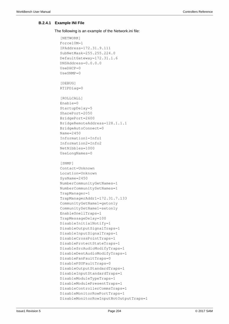
WorkBench User Manual Controllers Reference
B.2.4.1 Example INI File
The following is an example of the Network.ini file:
[NETWORK]Force10M=1IPAddress=172.31.9.111SubNetMask=255.255.224.0DefaultGateway=172.31.1.6DNSAddress=0.0.0.0UseDHCP=0UseSNMP=0
[DEBUG]RTIPDiag=0
[ROLLCALL]Enable=0StartupDelay=5SharePort=2050BridgePort=2600BridgeRemoteAddress=128.1.1.1BridgeAutoConnect=0Name=2450Information1=Info1Information2=Info2NetNibbles=1000UseLongNames=0
[SNMP]Contact=UnknownLocation=UnknownSysName=2450NumberCommunityGetNames=1NumberCommunitySetNames=1TrapManager=1TrapManagerAddr1=172.31.7.133CommunityGetName1=getonlyCommunitySetName1=setonlyEnableSnellTraps=1TrapMessageDelay=100DisableInitialNotify=1DisableOutputSignalTraps=1DisableInputSignalTraps=1DisableCrossPointTraps=1DisableProtectStateTraps=1DisableSrcAudioModifyTraps=1DisableDestAudioModifyTraps=1DisableFanFaultTraps=0DisablePSUFaultTraps=0DisableOutputStandardTraps=1DisableInputStandardTraps=1DisableModuleTypeTraps=1DisableModulePresentTraps=1DisableControllerCommsTraps=1DisableMonitorRowPortTraps=1DisableMonitorRowInputNotOutputTraps=1
Issue1 Revision 5 Page 204 © 2017 SAM
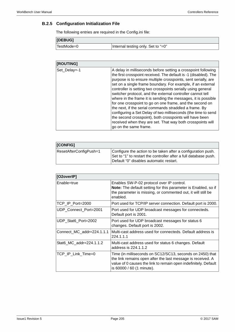
WorkBench User Manual Controllers Reference
B.2.5 Configuration Initialization File
The following entries are required in the Config.ini file:
[DEBUG]
TestMode=0 Internal testing only. Set to “=0”
[ROUTING]
Set_Delay=-1 A delay in milliseconds before setting a crosspoint following the first crosspoint received. The default is -1 (disabled). The purpose is to ensure multiple crosspoints, sent serially, are set on a single frame boundary. For example, if an external controller is setting two crosspoints serially using general switcher protocol, and the external controller cannot tell where in the frame it is sending the messages, it is possible for one crosspoint to go on one frame, and the second on the next, if the serial commands straddled a frame. By configuring a Set Delay of two milliseconds (the time to send the second crosspoint), both crosspoints will have been received when they are set. That way both crosspoints will go on the same frame.
[CONFIG]
ResetAfterConfigPush=1 Configure the action to be taken after a configuration push. Set to “1” to restart the controller after a full database push. Default “0” disables automatic restart.
[O2overIP]
Enable=true Enables SW-P-02 protocol over IP control.Note: The default setting for this parameter is Enabled, so if the parameter is missing, or commented out, it will still be enabled.
TCP_IP_Port=2000 Port used for TCP/IP server connection. Default port is 2000.
UDP_Connect_Port=2001 Port used for UDP broadcast messages for connecteds. Default port is 2001.
UDP_Stat6_Port=2002 Port used for UDP broadcast messages for status 6 changes. Default port is 2002.
Connect_MC_addr=224.1.1.1 Multi-cast address used for connecteds. Default address is 224.1.1.1
Stat6_MC_addr=224.1.1.2 Multi-cast address used for status 6 changes. Default address is 224.1.1.2
TCP_IP_Link_Time=0 Time (in milliseconds on SC12/SC13, seconds on 2450) that the link remains open after the last message is received. A value of 0 causes the link to remain open indefinitely. Default is 60000 / 60 (1 minute).
Issue1 Revision 5 Page 205 © 2017 SAM
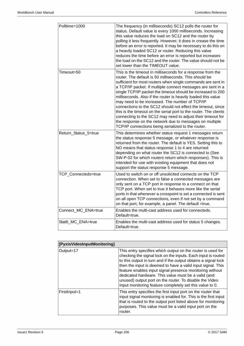
WorkBench User Manual Controllers Reference
Polltime=1000 The frequency (in milliseconds) SC12 polls the router for status. Default value is every 1000 milliseconds. Increasing this value reduces the load on SC12 and the router by polling it less frequently. However, it does in crease the time before an error is reported. It may be necessary to do this on a heavily loaded SC12 or router. Reducing this value reduces the time before an error is reported but increases the load on the SC12 and the router. The value should not be set lower than the TIMEOUT value.
Timeout=50 This is the timeout in milliseconds for a response from the router. The default is 50 milliseconds. This should be sufficient for most routers when single commands are sent in a TCP/IP packet. If multiple connect messages are sent in a single TCP/IP packet the timeout should be increased to 200 milliseconds. Also if the router is heavily loaded this value may need to be increased. The number of TCP/IP connections to the SC12 should not effect the timeout, since this is the timeout on the serial port to the router. The clients connecting to the SC12 may need to adjust their timeout for the response on the network due to messages on multiple TCP/IP connections being serialized to the router.
Return_Status_5=true This determines whether status request 1 messages return the status response 5 message, or whatever response is returned from the router. The default is YES. Setting this to NO means that status response 1 to 4 are returned depending on what router the SC12 is connected to (See SW-P-02 for which routers return which responses). This is intended for use with existing equipment that does not support the status response 5 message.
TCP_Connecteds=true Used to switch on or off unsolicited connects on the TCP connection. When set to false a connected messages are only sent on a TCP port in response to a connect on that TCP port. When set to true it behaves more like the serial ports in that whenever a crosspoint is set a connected is sent on all open TCP connections, even if not set by a command on that port, for example, a panel. The default =true.
Connect_MC_ENA=true Enables the multi-cast address used for connecteds. Default=true.
Stat6_MC_ENA=true Enables the multi-cast address used for status 5 changes. Default=true.
[PyxisVideoInputMonitoring]
Output=17 This entry specifies which output on the router is used for checking the signal lock on the inputs. Each input is routed to this output in turn and if the output obtains a signal lock then the input is deemed to have a valid input signal. This feature enables input signal presence monitoring without dedicated hardware. This value must be a valid (and unused) output port on the router. To disable the Video Input monitoring feature completely set this value to 0.
FirstInput=1 This entry specifies the first input port on the router that input signal monitoring is enabled for. This is the first input that is routed to the output port listed above for monitoring purposes. This value must be a valid input port on the router.
Issue1 Revision 5 Page 206 © 2017 SAM
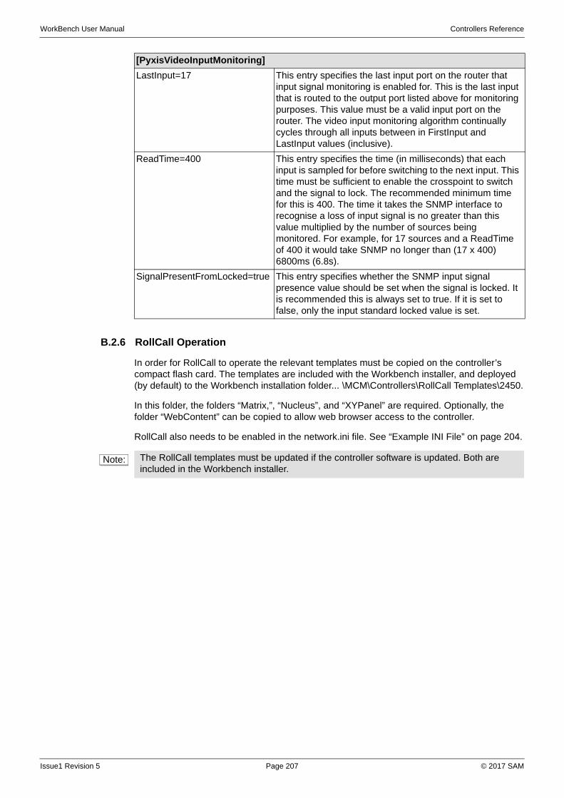
WorkBench User Manual Controllers Reference
B.2.6 RollCall Operation
In order for RollCall to operate the relevant templates must be copied on the controller’s compact flash card. The templates are included with the Workbench installer, and deployed (by default) to the Workbench installation folder... \MCM\Controllers\RollCall Templates\2450.
In this folder, the folders “Matrix,”, “Nucleus”, and “XYPanel” are required. Optionally, the folder “WebContent” can be copied to allow web browser access to the controller.
RollCall also needs to be enabled in the network.ini file. See “Example INI File” on page 204.
LastInput=17 This entry specifies the last input port on the router that input signal monitoring is enabled for. This is the last input that is routed to the output port listed above for monitoring purposes. This value must be a valid input port on the router. The video input monitoring algorithm continually cycles through all inputs between in FirstInput and LastInput values (inclusive).
ReadTime=400 This entry specifies the time (in milliseconds) that each input is sampled for before switching to the next input. This time must be sufficient to enable the crosspoint to switch and the signal to lock. The recommended minimum time for this is 400. The time it takes the SNMP interface to recognise a loss of input signal is no greater than this value multiplied by the number of sources being monitored. For example, for 17 sources and a ReadTime of 400 it would take SNMP no longer than (17 x 400) 6800ms (6.8s).
SignalPresentFromLocked=true This entry specifies whether the SNMP input signal presence value should be set when the signal is locked. It is recommended this is always set to true. If it is set to false, only the input standard locked value is set.
[PyxisVideoInputMonitoring]
Note: The RollCall templates must be updated if the controller software is updated. Both are included in the Workbench installer.
Issue1 Revision 5 Page 207 © 2017 SAM
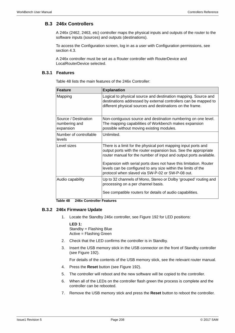
WorkBench User Manual Controllers Reference
B.3 246x Controllers
A 246x (2462, 2463, etc) controller maps the physical inputs and outputs of the router to the software inputs (sources) and outputs (destinations).
To access the Configuration screen, log in as a user with Configuration permissions, see section 4.3.
A 246x controller must be set as a Router controller with RouterDevice and LocalRouterDevice selected.
B.3.1 Features
Table 48 lists the main features of the 246x Controller:
B.3.2 246x Firmware Update
1. Locate the Standby 246x controller, see Figure 192 for LED positions:
LED 1: Standby = Flashing BlueActive = Flashing Green
2. Check that the LED confirms the controller is in Standby.
3. Insert the USB memory stick in the USB connector on the front of Standby controller (see Figure 192).
For details of the contents of the USB memory stick, see the relevant router manual.
4. Press the Reset button (see Figure 192).
5. The controller will reboot and the new software will be copied to the controller.
6. When all of the LEDs on the controller flash green the process is complete and the controller can be rebooted.
7. Remove the USB memory stick and press the Reset button to reboot the controller.
Feature Explanation
Mapping Logical to physical source and destination mapping. Source and destinations addressed by external controllers can be mapped to different physical sources and destinations on the frame.
Source / Destination numbering and expansion
Non-contiguous source and destination numbering on one level. The mapping capabilities of Workbench makes expansion possible without moving existing modules.
Number of controllable levels
Unlimited.
Level sizes There is a limit for the physical port mapping input ports and output ports with the router expansion bus. See the appropriate router manual for the number of input and output ports available.
Expansion with serial ports does not have this limitation. Router levels can be configured to any size within the limits of the protocol when slaved via SW-P-02 or SW-P-08 out.
Audio capability Up to 32 channels of Mono, Stereo or Dolby ‘grouped’ routing and processing on a per channel basis.
See compatible routers for details of audio capabilities.
Table 48 246x Controller Features
Issue1 Revision 5 Page 208 © 2017 SAM
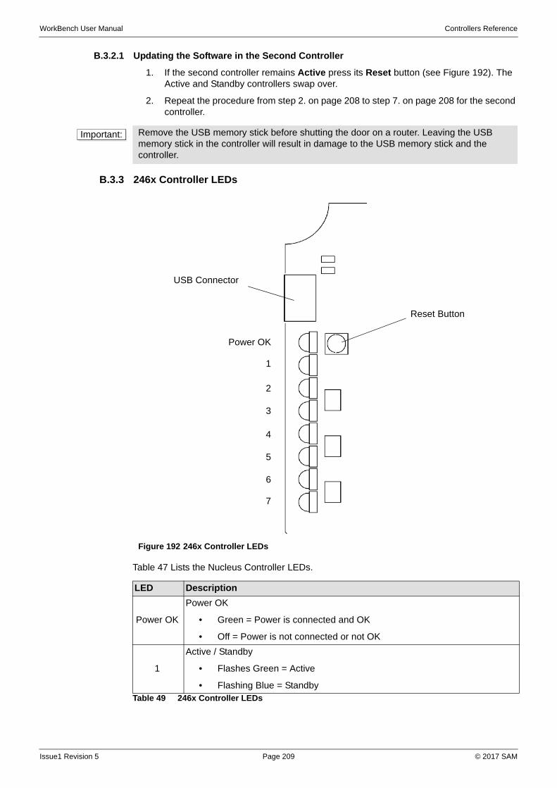
WorkBench User Manual Controllers Reference
B.3.2.1 Updating the Software in the Second Controller
1. If the second controller remains Active press its Reset button (see Figure 192). The Active and Standby controllers swap over.
2. Repeat the procedure from step 2. on page 208 to step 7. on page 208 for the second controller.
B.3.3 246x Controller LEDs
Table 47 Lists the Nucleus Controller LEDs.
Important: Remove the USB memory stick before shutting the door on a router. Leaving the USB memory stick in the controller will result in damage to the USB memory stick and the controller.
Figure 192 246x Controller LEDs
LED Description
Power OK
Power OK
• Green = Power is connected and OK
• Off = Power is not connected or not OK
1
Active / Standby
• Flashes Green = Active
• Flashing Blue = StandbyTable 49 246x Controller LEDs
Reset Button
USB Connector
1
Power OK
2
3
4
5
6
7
Issue1 Revision 5 Page 209 © 2017 SAM
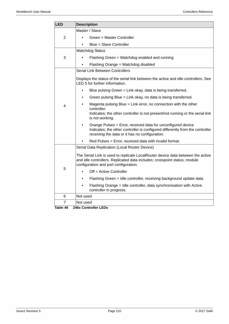
WorkBench User Manual Controllers Reference
2
Master / Slave
• Green = Master Controller
• Blue = Slave Controller
3
Watchdog Status
• Flashing Green = Watchdog enabled and running
• Flashing Orange = Watchdog disabled
4
Serial Link Between Controllers
Displays the status of the serial link between the active and idle controllers. See LED 5 for further information.
• Blue pulsing Green = Link okay, data is being transferred.
• Green pulsing Blue = Link okay, no data is being transferred.
• Magenta pulsing Blue = Link error, no connection with the other controller. Indicates; the other controller is not present/not running or the serial link is not working.
• Orange Pulses = Error, received data for unconfigured deviceIndicates; the other controller is configured differently from the controller receiving the data or it has no configuration.
• Red Pulses = Error, received data with invalid format.
5
Serial Data Replication (Local Router Device)
The Serial Link is used to replicate LocalRouter device data between the active and idle controllers. Replicated data includes; crosspoint status, module configuration and port configuration.
• Off = Active Controller
• Flashing Green = Idle controller, receiving background update data.
• Flashing Orange = Idle controller, data synchronisation with Active controller in progress.
6 Not used
7 Not used
LED Description
Table 49 246x Controller LEDs
Issue1 Revision 5 Page 210 © 2017 SAM
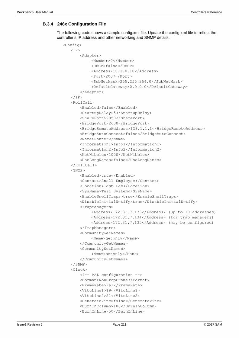
WorkBench User Manual Controllers Reference
B.3.4 246x Configuration File
The following code shows a sample config.xml file. Update the config.xml file to reflect the controller’s IP address and other networking and SNMP details.
<Config><IP>
<Adapter><Number>0</Number><DHCP>false</DHCP><Address>10.1.0.10</Address><Port>2007</Port><SubNetMask>255.255.254.0</SubNetMask><DefaultGateway>0.0.0.0</DefaultGateway>
</Adapter></IP><RollCall>
<Enabled>false</Enabled> <StartupDelay>5</StartupDelay> <SharePort>2050</SharePort> <BridgePort>2600</BridgePort> <BridgeRemoteAddress>128.1.1.1</BridgeRemoteAddress> <BridgeAutoConnect>false</BridgeAutoConnect> <Name>Router</Name> <Information1>Info1</Information1> <Information2>Info2</Information2> <NetNibbles>1000</NetNibbles> <UseLongNames>false</UseLongNames>
</RollCall><SNMP>
<Enabled>true</Enabled><Contact>Snell Employee</Contact><Location>Test Lab</Location><SysName>Test System</SysName><EnableSnellTraps>true</EnableSnellTraps><DisableInitialNotify>true</DisableInitialNotify><TrapManagers>
<Address>172.31.7.133</Address> (up to 10 addresses)<Address>172.31.7.134</Address> (for trap managers)<Address>172.31.7.135</Address> (may be configured)
</TrapManagers><CommunityGetNames>
<Name>getonly</Name></CommunityGetNames><CommunitySetNames>
<Name>setonly</Name></CommunitySetNames>
</SNMP><Clock>
<!-- PAL configuration --><Format>NonDropFrame</Format><FrameRate>Pal</FrameRate><VitcLine1>19</VitcLine1><VitcLine2>21</VitcLine2><GenerateVitc>false</GenerateVitc><BurnInColumn>100</BurnInColumn><BurnInLine>50</BurnInLine>
Issue1 Revision 5 Page 211 © 2017 SAM
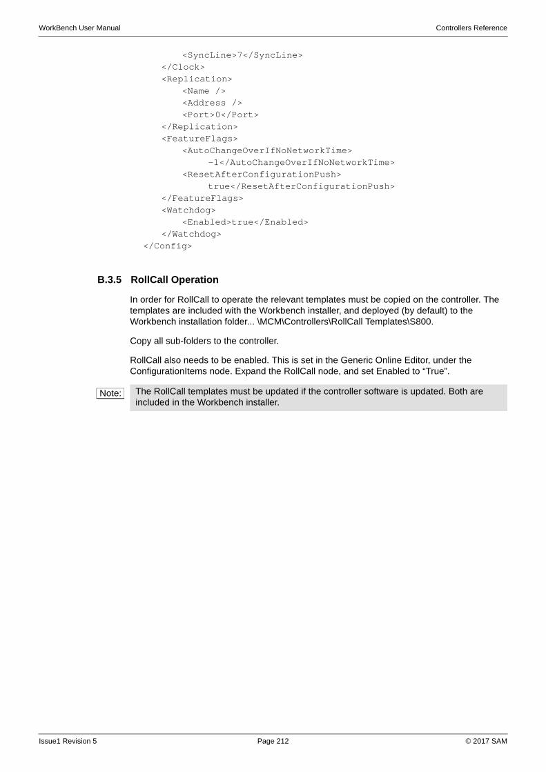
WorkBench User Manual Controllers Reference
<SyncLine>7</SyncLine></Clock><Replication>
<Name /> <Address /> <Port>0</Port>
</Replication><FeatureFlags>
<AutoChangeOverIfNoNetworkTime>-1</AutoChangeOverIfNoNetworkTime>
<ResetAfterConfigurationPush>true</ResetAfterConfigurationPush>
</FeatureFlags><Watchdog>
<Enabled>true</Enabled></Watchdog>
</Config>
B.3.5 RollCall Operation
In order for RollCall to operate the relevant templates must be copied on the controller. The templates are included with the Workbench installer, and deployed (by default) to the Workbench installation folder... \MCM\Controllers\RollCall Templates\S800.
Copy all sub-folders to the controller.
RollCall also needs to be enabled. This is set in the Generic Online Editor, under the ConfigurationItems node. Expand the RollCall node, and set Enabled to “True”.
Note: The RollCall templates must be updated if the controller software is updated. Both are included in the Workbench installer.
Issue1 Revision 5 Page 212 © 2017 SAM

WorkBench User Manual Controllers Reference
B.4 RollCall Gateway
To configure a RollCall Gateway:
1. Navigate to the configuration screen and add a RollCall controller.
2. Ensure that connection to the controller has been established by checking the connection state icon.
3. When connection has been established, Workbench automatically initiates discovery of the RollCall network. Note that it may take several minutes to complete discovery of a network the first time round. Information about the network is cached in order to speed up future discovery attempts.
4. Open the online generic editor and expand the Frames Detected branch. The branch may be populated with a set of one or more subnets, each of which may be populated with a set of one or more racks.
5. Close the online editor and pull the controller's configuration.
6. Open the offline generic editor. The Frames Detected branch should contain a snapshot of the live network.
7. Right-click on the Frames Detected node and select Copy. Right-click on the Frames node and select Paste. A copy of the detected branch should appear underneath the Frames node.
Issue1 Revision 5 Page 213 © 2017 SAM

WorkBench User Manual Controllers Reference
Issue1 Revision 5 Page 214 © 2017 SAM
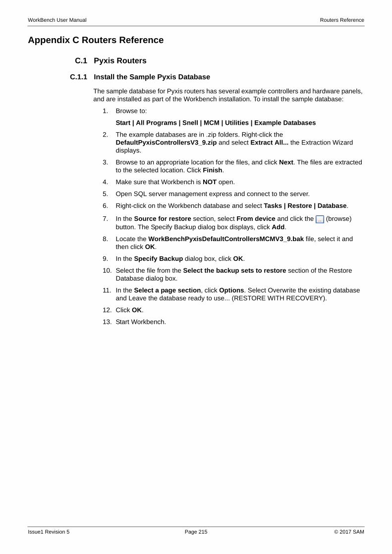
WorkBench User Manual Routers Reference
Appendix C Routers Reference
C.1 Pyxis Routers
C.1.1 Install the Sample Pyxis Database
The sample database for Pyxis routers has several example controllers and hardware panels, and are installed as part of the Workbench installation. To install the sample database:
1. Browse to:
Start | All Programs | Snell | MCM | Utilities | Example Databases
2. The example databases are in .zip folders. Right-click the DefaultPyxisControllersV3_9.zip and select Extract All... the Extraction Wizard displays.
3. Browse to an appropriate location for the files, and click Next. The files are extracted to the selected location. Click Finish.
4. Make sure that Workbench is NOT open.
5. Open SQL server management express and connect to the server.
6. Right-click on the Workbench database and select Tasks | Restore | Database.
7. In the Source for restore section, select From device and click the (browse) button. The Specify Backup dialog box displays, click Add.
8. Locate the WorkBenchPyxisDefaultControllersMCMV3_9.bak file, select it and then click OK.
9. In the Specify Backup dialog box, click OK.
10. Select the file from the Select the backup sets to restore section of the Restore Database dialog box.
11. In the Select a page section, click Options. Select Overwrite the existing database and Leave the database ready to use... (RESTORE WITH RECOVERY).
12. Click OK.
13. Start Workbench.
Issue1 Revision 5 Page 215 © 2017 SAM
WorkBench User Manual Routers Reference
C.1.2 Sample Controllers
Each controller has a standard set of control panels supplied in the sample database.
C.1.2.1 Pyxis AES - 144x144 Ref1
Dual 2450 Nucleus controller configured with independent IP address that controls a single level of routing up to 144x144 AES (actual router size is dependent on cards and rear connectors fitted to Pyxis frame). All MADI Inputs and Outputs have been hidden (mapped out) in the Logical to Physical port mapping tables so that controller is purely the AES inputs and outputs only.
Pyxis Serial port configuration:
Port 1 (Workbench COM 3) = General Switcher In (SW-P-02) for Aurora control
Port 2 (Workbench COM 4) = General Switcher In (SW-P-02) for Aurora control
Port 3 (Workbench COM 5) = Panel Protocol with a 6276 X-Y configured for numerical control of all inputs and outputs on address 1
Reference 1 has been configured as the primary reference source for all inputs
C.1.2.2 Pyxis AA - 144x144 Stereo Ref1
Dual 2450 Nucleus controller configured with independent IP address that controls a single level of routing up to 144x144 Stereo (actual router size is dependent on cards and rear connectors fitted to Pyxis frame). All MADI Inputs and Outputs have been hidden (mapped out) in the Logical to Physical port mapping tables so that controller is purely the Stereo inputs and outputs only
Pyxis Serial port configuration:
Port 1 (Workbench COM 3) = General Switcher In (SW-P-02) for Aurora control
Port 2 (Workbench COM 4) = General Switcher In (SW-P-02) for Aurora control
Port 3 (Workbench COM 5) = Panel Protocol with a 6276 X-Y configured for numerical control of all inputs and outputs on address 1
Reference 1 has been configured as the primary reference source for all inputs
C.1.2.3 Pyxis AA - 272x272 Stereo (64 MADI) Ref1
Dual 2450 Nucleus controller configured with independent IP address that controls a single level of routing up to 272x272 Stereo (actual router size is dependent on cards and rear connectors fitted to Pyxis frame). All MADI Inputs and Outputs are exposed in the Logical to Physical port mapping tables as pairs so that they are controllable, please refer to the Pyxis handbook “Audio Port Numbering” section for more details
Pyxis Serial port configuration:
Port 1 (Workbench COM 3) = General Switcher In (SW-P-02) for Aurora control
Port 2 (Workbench COM 4) = General Switcher In (SW-P-02) for Aurora control
Port 3 (Workbench COM 5) = Panel Protocol with a 6276 X-Y configured for numerical control of all inputs and outputs on address 1
Reference 1 has been configured as the primary reference source for all inputs
Issue1 Revision 5 Page 216 © 2017 SAM
WorkBench User Manual Routers Reference
C.1.2.4 Pyxis AA - 288x288 Mono Ref1
Dual 2450 Nucleus controller configured with independent IP address that controls a single level of routing up to 288x288 MONO (actual router size is dependent on cards and rear connectors fitted to Pyxis frame). All MADI Inputs and Outputs have been hidden (mapped out) in the Logical to Physical port mapping tables so that controller is purely the MONO inputs and outputs only
Pyxis Serial port configuration:
Port 1 (Workbench COM 3) = General Switcher In (SW-P-02) for Aurora control
Port 2 (Workbench COM 4) = General Switcher In (SW-P-02) for Aurora control
Port 3 (Workbench COM 5) = Panel Protocol with a 6276 X-Y configured for numerical control of all inputs and outputs on address 1
Reference 1 has been configured as the primary reference source for all inputs
C.1.2.5 Pyxis AA - 544x544 Mono (64 MADI) A Ref1
Dual 2450 Nucleus controller configured with independent IP address that controls a single level of routing up to 544x544 MONO (actual router size is dependent on cards and rear connectors fitted to Pyxis frame). All MADI Inputs and Outputs are exposed in the Logical to Physical port mapping tables on to one so that they are controllable please refer to the Pyxis handbook “Audio Port Numbering” section for more details
Pyxis Serial port configuration:
Port 1 (Workbench COM 3) = General Switcher In (SW-P-02) for Aurora control
Port 2 (Workbench COM 4) = General Switcher In (SW-P-02) for Aurora control
Port 3 (Workbench COM 5) = Panel Protocol with a 6276 X-Y configured for numerical control of all inputs and outputs on address 1
Reference 1 has been configured as the primary reference source for all inputs
C.1.2.6 Pyxis Video - 72x72 Ref1
Dual 2450 Nucleus controller configured with independent IP address that controls a single level of routing up to 72x72 Video (Video signal format and actual router size is dependent on cards and rear connectors fitted to Pyxis frame)
Pyxis Serial port configuration:
Port 1 (Workbench COM 3) = General Switcher In (SW-P-02) for Aurora control
Port 2 (Workbench COM 4) = General Switcher In (SW-P-02) for Aurora control
Port 3 (Workbench COM 5) = Panel Protocol with a 6276 X-Y configured for numerical control of all inputs and outputs on address 1
Reference 1 has been configured as the primary reference source for all inputs
Issue1 Revision 5 Page 217 © 2017 SAM
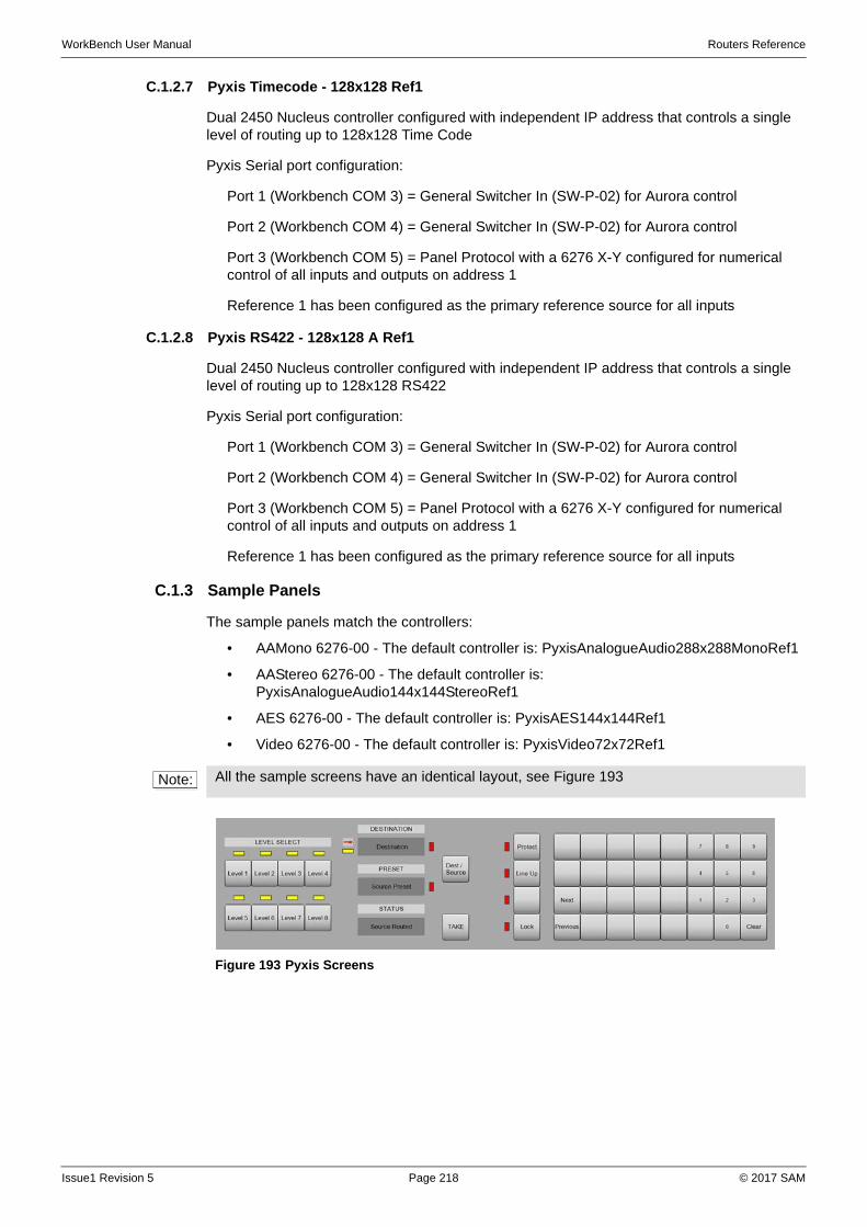
WorkBench User Manual Routers Reference
C.1.2.7 Pyxis Timecode - 128x128 Ref1
Dual 2450 Nucleus controller configured with independent IP address that controls a single level of routing up to 128x128 Time Code
Pyxis Serial port configuration:
Port 1 (Workbench COM 3) = General Switcher In (SW-P-02) for Aurora control
Port 2 (Workbench COM 4) = General Switcher In (SW-P-02) for Aurora control
Port 3 (Workbench COM 5) = Panel Protocol with a 6276 X-Y configured for numerical control of all inputs and outputs on address 1
Reference 1 has been configured as the primary reference source for all inputs
C.1.2.8 Pyxis RS422 - 128x128 A Ref1
Dual 2450 Nucleus controller configured with independent IP address that controls a single level of routing up to 128x128 RS422
Pyxis Serial port configuration:
Port 1 (Workbench COM 3) = General Switcher In (SW-P-02) for Aurora control
Port 2 (Workbench COM 4) = General Switcher In (SW-P-02) for Aurora control
Port 3 (Workbench COM 5) = Panel Protocol with a 6276 X-Y configured for numerical control of all inputs and outputs on address 1
Reference 1 has been configured as the primary reference source for all inputs
C.1.3 Sample Panels
The sample panels match the controllers:
• AAMono 6276-00 - The default controller is: PyxisAnalogueAudio288x288MonoRef1
• AAStereo 6276-00 - The default controller is: PyxisAnalogueAudio144x144StereoRef1
• AES 6276-00 - The default controller is: PyxisAES144x144Ref1
• Video 6276-00 - The default controller is: PyxisVideo72x72Ref1
Note: All the sample screens have an identical layout, see Figure 193
Figure 193 Pyxis Screens
Issue1 Revision 5 Page 218 © 2017 SAM
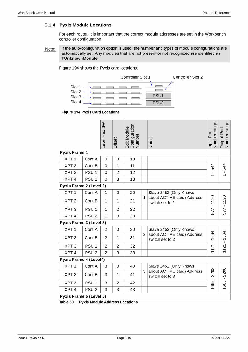
WorkBench User Manual Routers Reference
C.1.4 Pyxis Module Locations
For each router, it is important that the correct module addresses are set in the Workbench controller configuration.
Figure 194 shows the Pyxis card locations.
Note: If the auto-configuration option is used, the number and types of module configurations are automatically set. Any modules that are not present or not recognized are identified as TUnknownModule.
Figure 194 Pyxis Card Locations
Lev
el H
ex S
W
Offs
et
Edi
t Mod
ule
Co
nfig
ura
tion
N
um
be
r
No
tes
Inpu
t P
ort
Num
ber
rang
e
Out
pu
t Po
rt
Num
ber
rang
e
Pyxis Frame 1
XPT 1 Cont A 0 0 10
1 -
54
4
1 -
54
4XPT 2 Cont B 0 1 11
XPT 3 PSU 1 0 2 12
XPT 4 PSU 2 0 3 13
Pyxis Frame 2 (Level 2)
XPT 1 Cont A 1 0 201
Slave 2452 (Only Knows about ACTIVE card) Address switch set to 1
577
- 1
120
577
- 1
120
XPT 2 Cont B 1 1 21
XPT 3 PSU 1 1 2 22
XPT 4 PSU 2 1 3 23
Pyxis Frame 3 (Level 3)
XPT 1 Cont A 2 0 302
Slave 2452 (Only Knows about ACTIVE card) Address switch set to 2
1121
- 1
664
1121
- 1
664
XPT 2 Cont B 2 1 31
XPT 3 PSU 1 2 2 32
XPT 4 PSU 2 2 3 33
Pyxis Frame 4 (Level4)
XPT 1 Cont A 3 0 403
Slave 2452 (Only Knows about ACTIVE card) Address switch set to 3
166
5 -
22
08
166
5 -
22
08
XPT 2 Cont B 3 1 41
XPT 3 PSU 1 3 2 42
XPT 4 PSU 2 3 3 43
Pyxis Frame 5 (Level 5)Table 50 Pyxis Module Address Locations
Slot 1Slot 2Slot 3Slot 4
Controller Slot 1 Controller Slot 2
PSU1
PSU2
Issue1 Revision 5 Page 219 © 2017 SAM
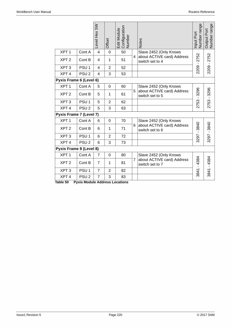
WorkBench User Manual Routers Reference
XPT 1 Cont A 4 0 504
Slave 2452 (Only Knows about ACTIVE card) Address switch set to 4
220
9 -
275
2
220
9 -
275
2
XPT 2 Cont B 4 1 51
XPT 3 PSU 1 4 2 52
XPT 4 PSU 2 4 3 53
Pyxis Frame 6 (Level 6)
XPT 1 Cont A 5 0 605
Slave 2452 (Only Knows about ACTIVE card) Address switch set to 5
275
3 -
3296
275
3 -
3296
XPT 2 Cont B 5 1 61
XPT 3 PSU 1 5 2 62
XPT 4 PSU 2 5 3 63
Pyxis Frame 7 (Level 7)
XPT 1 Cont A 6 0 706
Slave 2452 (Only Knows about ACTIVE card) Address switch set to 6
329
7 -
38
40
329
7 -
38
40
XPT 2 Cont B 6 1 71
XPT 3 PSU 1 6 2 72
XPT 4 PSU 2 6 3 73
Pyxis Frame 8 (Level 8)
XPT 1 Cont A 7 0 807
Slave 2452 (Only Knows about ACTIVE card) Address switch set to 7
3841
- 4
384
3841
- 4
384
XPT 2 Cont B 7 1 81
XPT 3 PSU 1 7 2 82
XPT 4 PSU 2 7 3 83
Leve
l Hex
SW
Offs
et
Edi
t M
odul
e C
onfig
urat
ion
N
umb
er
Not
es
Inp
ut P
ort
N
umb
er r
an
ge
Out
put
Por
t N
umb
er r
an
ge
Table 50 Pyxis Module Address Locations
Issue1 Revision 5 Page 220 © 2017 SAM
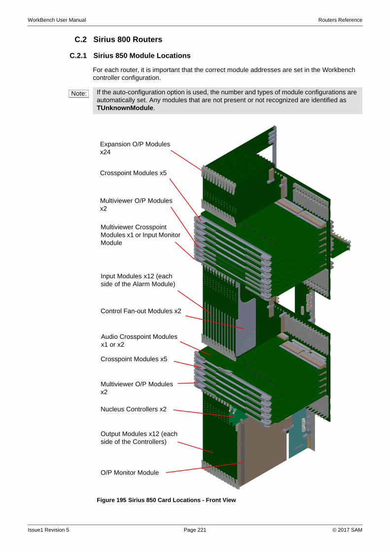
WorkBench User Manual Routers Reference
C.2 Sirius 800 Routers
C.2.1 Sirius 850 Module Locations
For each router, it is important that the correct module addresses are set in the Workbench controller configuration.
Note: If the auto-configuration option is used, the number and types of module configurations are automatically set. Any modules that are not present or not recognized are identified as TUnknownModule.
Figure 195 Sirius 850 Card Locations - Front View
Expansion O/P Modulesx24
Crosspoint Modules x5
Multiviewer O/P Modulesx2
Multiviewer Crosspoint Modules x1 or Input Monitor Module
Input Modules x12 (each side of the Alarm Module)
Control Fan-out Modules x2
Crosspoint Modules x5
Multiviewer O/P Modules x2
Nucleus Controllers x2
Output Modules x12 (each side of the Controllers)
O/P Monitor Module
Audio Crosspoint Modules x1 or x2
Issue1 Revision 5 Page 221 © 2017 SAM
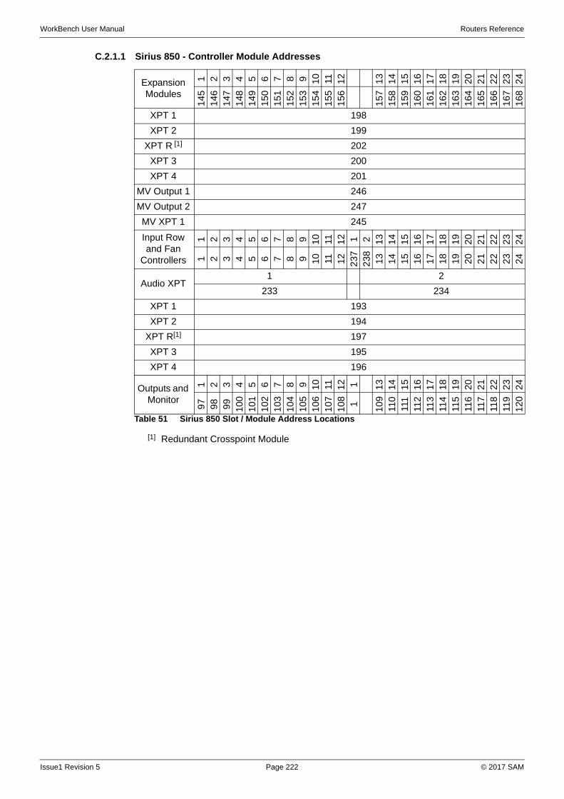
WorkBench User Manual Routers Reference
C.2.1.1 Sirius 850 - Controller Module Addresses
Expansion Modules
1 2 3 4 5 6 7 8 9 10 11 12
13
14
15
16
17
18
19
20
21
22
23
24
145
146
147
148
149
150
151
152
153
154
155
156
157
158
159
160
161
162
163
164
165
166
167
168
XPT 1 198
XPT 2 199
XPT R [1]
[1] Redundant Crosspoint Module
202
XPT 3 200
XPT 4 201
MV Output 1 246
MV Output 2 247
MV XPT 1 245
Input Row and Fan
Controllers
1 2 3 4 5 6 7 8 9 10 11 12 1 2 13
14
15
16
17
18
19
20
21
22
23
24
1 2 3 4 5 6 7 8 9 10 11 12 237
238 13 14 15 16 17 18 19 20 21 22 23 24
Audio XPT1 2
233 234
XPT 1 193
XPT 2 194
XPT R[1] 197
XPT 3 195
XPT 4 196
Outputs and Monitor
1 2 3 4 5 6 7 8 9 10 11 12 1 13
14
15
16
17
18
19
20
21
22
23
24
97
98
99
100
101
102
103
104
105
106
107
108 1
109 110
111
112
113
114
115
116
117
118
119
120
Table 51 Sirius 850 Slot / Module Address Locations
Issue1 Revision 5 Page 222 © 2017 SAM
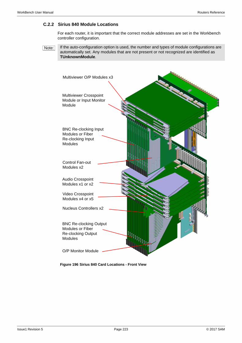
WorkBench User Manual Routers Reference
C.2.2 Sirius 840 Module Locations
For each router, it is important that the correct module addresses are set in the Workbench controller configuration.
Note: If the auto-configuration option is used, the number and types of module configurations are automatically set. Any modules that are not present or not recognized are identified as TUnknownModule.
Figure 196 Sirius 840 Card Locations - Front View
Multiviewer O/P Modules x3
Multiviewer Crosspoint Module or Input Monitor Module
BNC Re-clocking Input Modules or Fiber Re-clocking Input Modules
Control Fan-out Modules x2
Audio Crosspoint Modules x1 or x2
Nucleus Controllers x2
BNC Re-clocking Output Modules or Fiber Re-clocking Output Modules
O/P Monitor Module
Video Crosspoint Modules x4 or x5
Issue1 Revision 5 Page 223 © 2017 SAM
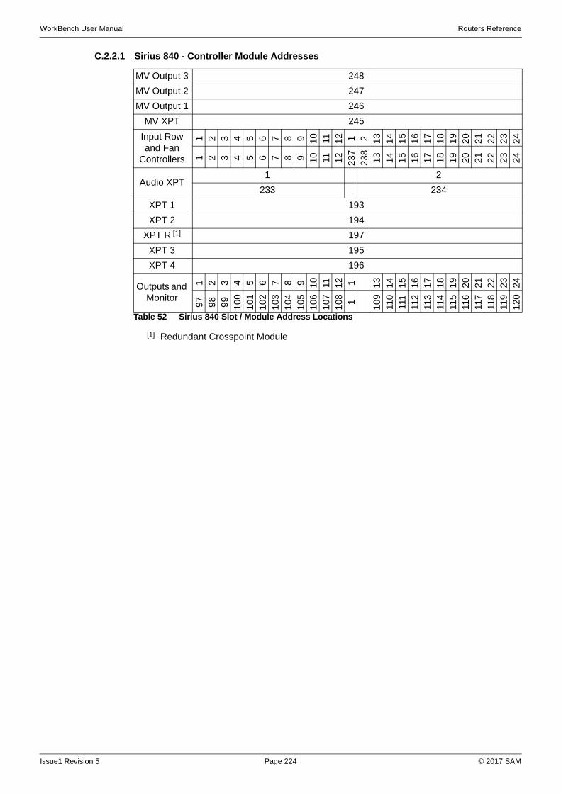
WorkBench User Manual Routers Reference
C.2.2.1 Sirius 840 - Controller Module Addresses
MV Output 3 248
MV Output 2 247
MV Output 1 246
MV XPT 245
Input Row and Fan
Controllers
1 2 3 4 5 6 7 8 9 10 11 12 1 2 13
14
15
16
17
18
19
20
21
22
23
24
1 2 3 4 5 6 7 8 9 10 11 12 23
72
38
13 14 15 16 17 18 19 20 21 22 23 24
Audio XPT1 2
233 234
XPT 1 193
XPT 2 194
XPT R [1]
[1] Redundant Crosspoint Module
197
XPT 3 195
XPT 4 196
Outputs and Monitor
1 2 3 4 5 6 7 8 9 10 11 12 1 13
14
15
16
17
18
19
20
21
22
23
24
97
98
99
100
101
102
103
104
105
106
107
108 1
109 110
111
112
113
114
115
116
117
118
119
120
Table 52 Sirius 840 Slot / Module Address Locations
Issue1 Revision 5 Page 224 © 2017 SAM
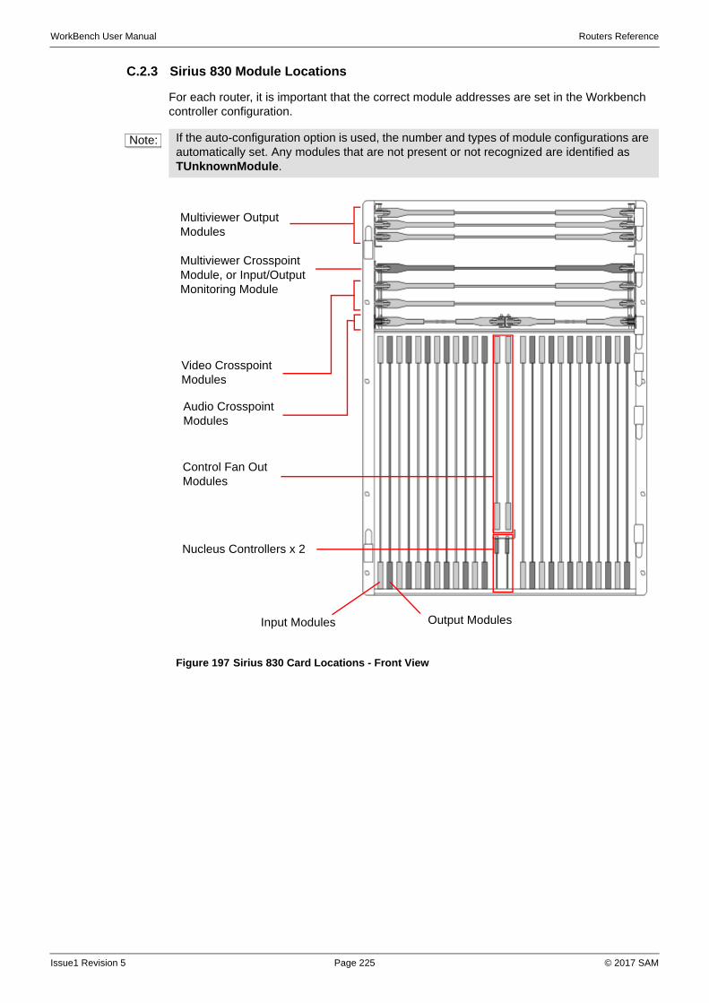
WorkBench User Manual Routers Reference
C.2.3 Sirius 830 Module Locations
For each router, it is important that the correct module addresses are set in the Workbench controller configuration.
Note: If the auto-configuration option is used, the number and types of module configurations are automatically set. Any modules that are not present or not recognized are identified as TUnknownModule.
Figure 197 Sirius 830 Card Locations - Front View
Multiviewer Crosspoint Module, or Input/Output Monitoring Module
Multiviewer Output Modules
Output Modules
Video Crosspoint Modules
Audio Crosspoint Modules
Control Fan Out Modules
Nucleus Controllers x 2
Input Modules
Issue1 Revision 5 Page 225 © 2017 SAM
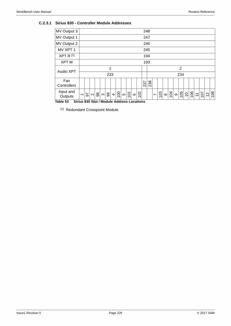
WorkBench User Manual Routers Reference
C.2.3.1 Sirius 830 - Controller Module Addresses
MV Output 3 248
MV Output 1 247
MV Output 2 246
MV XPT 1 245
XPT R [1]
[1] Redundant Crosspoint Module
194
XPT M 193
Audio XPT1 2
233 234
Fan Controllers 2
372
38
Input and Outputs 1 97 2 98 3 99 4
100 5
101 6
102 7
103 8
104 9
105 10 106 11 107 12 108
Table 53 Sirius 830 Slot / Module Address Locations
Issue1 Revision 5 Page 226 © 2017 SAM
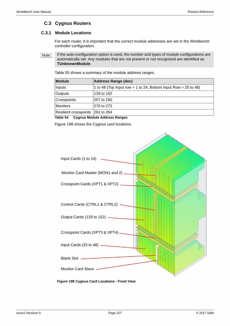
WorkBench User Manual Routers Reference
C.3 Cygnus Routers
C.3.1 Module Locations
For each router, it is important that the correct module addresses are set in the Workbench controller configuration.
Table 55 shows a summary of the module address ranges.
Figure 198 shows the Cygnus card locations.
Note: If the auto-configuration option is used, the number and types of module configurations are automatically set. Any modules that are not present or not recognized are identified as TUnknownModule.
Module Address Range (dec)
Inputs 1 to 48 (Top Input row = 1 to 24, Bottom Input Row = 25 to 48)
Outputs 129 to 152
Crosspoints 257 to 260
Monitors 270 to 272
Resilient crosspoints 261 to 264Table 54 Cygnus Module Address Ranges
Figure 198 Cygnus Card Locations - Front View
Input Cards (1 to 24)
Monitor Card Master (MON1 and 2)
Crosspoint Cards (XPT1 & XPT2)
Control Cards (CTRL1 & CTRL2)
Output Cards (129 to 152)
Crosspoint Cards (XPT3 & XPT4)
Input Cards (25 to 48)
Monitor Card Slave
Blank Slot
Issue1 Revision 5 Page 227 © 2017 SAM
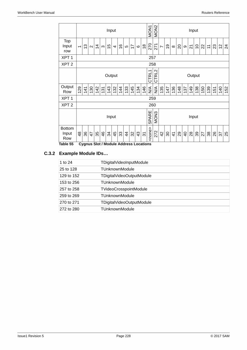
WorkBench User Manual Routers Reference
C.3.2 Example Module IDs…
Input
MO
N1
MO
N2
Input
Top Input row
1 13 2 14 3 15 4 16 5 17 6 18 27
0
27
1
7 19 8 20 9 21 10 22 11 23 12 24
XPT 1 257
XPT 2 258
Output
CT
RL
1
CT
RL
2
Output
Output Row 1
29
141
130
142
131
143
132
144
133
145
134
146
N/A
N/A
135
147
136
148
137
149
138
150
139
151
140
152
XPT 1 259
XPT 2 260
Input
SP
AR
E
MO
N3
Input
Bottom Input Row
48
36
47
35
46
34
45
33
44
32
43
31
<no
ne>
272 42
30
41
29
40
28
39
27
38
26
37
25
Table 55 Cygnus Slot / Module Address Locations
1 to 24 TDigitalVideoInputModule
25 to 128 TUnknownModule
129 to 152 TDigitalVideoOutputModule
153 to 256 TUnknownModule
257 to 258 TVideoCrosspointModule
259 to 269 TUnknownModule
270 to 271 TDigitalVideoOutputModule
272 to 280 TUnknownModule
Issue1 Revision 5 Page 228 © 2017 SAM
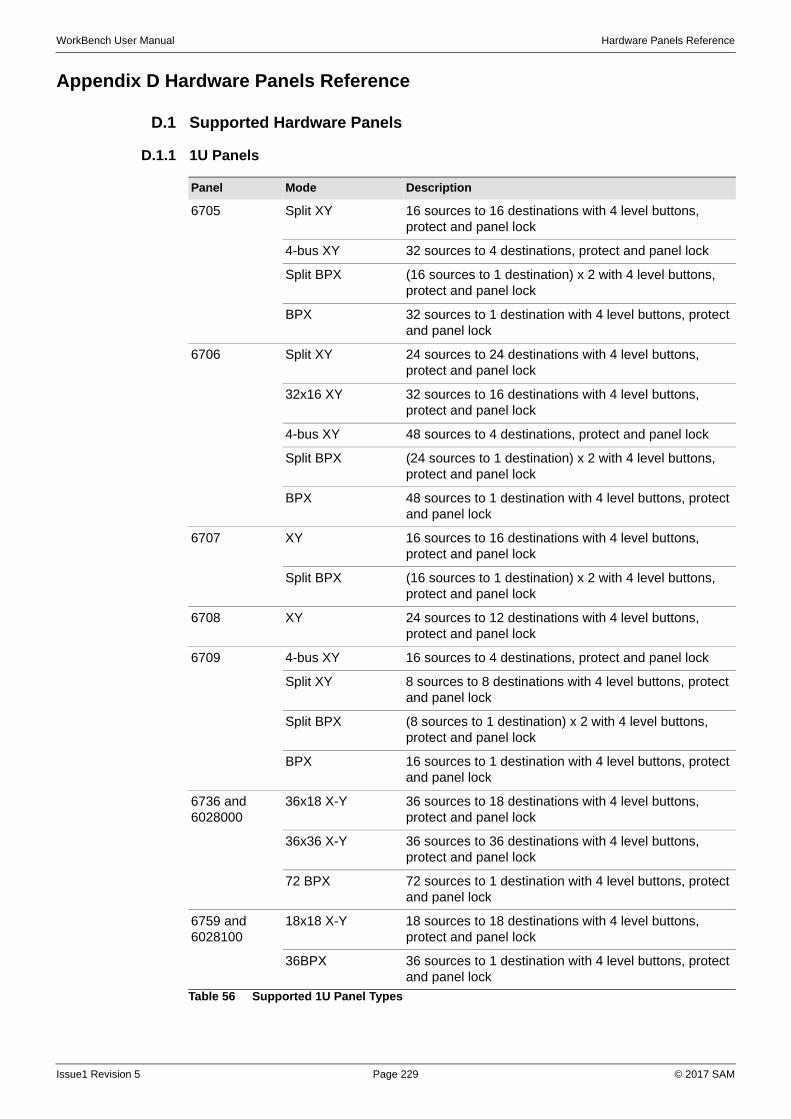
WorkBench User Manual Hardware Panels Reference
Appendix D Hardware Panels Reference
D.1 Supported Hardware Panels
D.1.1 1U Panels-
Panel Mode Description
6705 Split XY 16 sources to 16 destinations with 4 level buttons, protect and panel lock
4-bus XY 32 sources to 4 destinations, protect and panel lock
Split BPX (16 sources to 1 destination) x 2 with 4 level buttons, protect and panel lock
BPX 32 sources to 1 destination with 4 level buttons, protect and panel lock
6706 Split XY 24 sources to 24 destinations with 4 level buttons, protect and panel lock
32x16 XY 32 sources to 16 destinations with 4 level buttons, protect and panel lock
4-bus XY 48 sources to 4 destinations, protect and panel lock
Split BPX (24 sources to 1 destination) x 2 with 4 level buttons, protect and panel lock
BPX 48 sources to 1 destination with 4 level buttons, protect and panel lock
6707 XY 16 sources to 16 destinations with 4 level buttons, protect and panel lock
Split BPX (16 sources to 1 destination) x 2 with 4 level buttons, protect and panel lock
6708 XY 24 sources to 12 destinations with 4 level buttons, protect and panel lock
6709 4-bus XY 16 sources to 4 destinations, protect and panel lock
Split XY 8 sources to 8 destinations with 4 level buttons, protect and panel lock
Split BPX (8 sources to 1 destination) x 2 with 4 level buttons, protect and panel lock
BPX 16 sources to 1 destination with 4 level buttons, protect and panel lock
6736 and 6028000
36x18 X-Y 36 sources to 18 destinations with 4 level buttons, protect and panel lock
36x36 X-Y 36 sources to 36 destinations with 4 level buttons, protect and panel lock
72 BPX 72 sources to 1 destination with 4 level buttons, protect and panel lock
6759 and6028100
18x18 X-Y 18 sources to 18 destinations with 4 level buttons, protect and panel lock
36BPX 36 sources to 1 destination with 4 level buttons, protect and panel lock
Table 56 Supported 1U Panel Types
Issue1 Revision 5 Page 229 © 2017 SAM
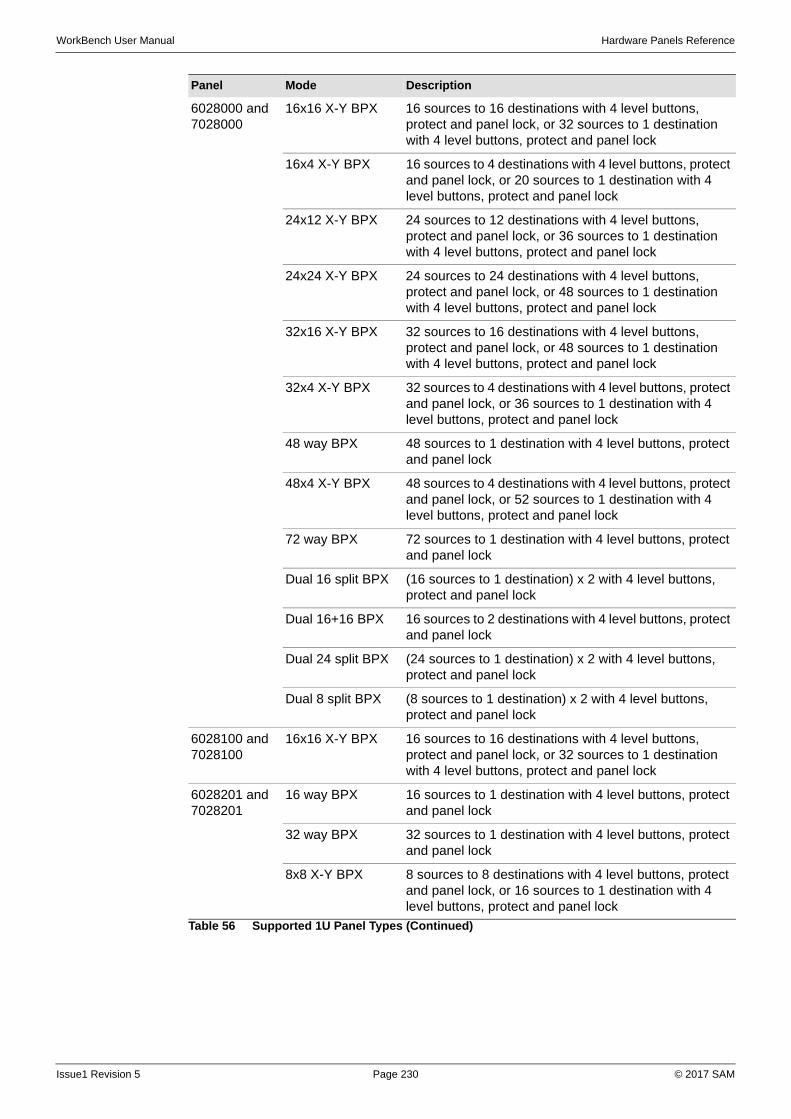
WorkBench User Manual Hardware Panels Reference
6028000 and 7028000
16x16 X-Y BPX 16 sources to 16 destinations with 4 level buttons, protect and panel lock, or 32 sources to 1 destination with 4 level buttons, protect and panel lock
16x4 X-Y BPX 16 sources to 4 destinations with 4 level buttons, protect and panel lock, or 20 sources to 1 destination with 4 level buttons, protect and panel lock
24x12 X-Y BPX 24 sources to 12 destinations with 4 level buttons, protect and panel lock, or 36 sources to 1 destination with 4 level buttons, protect and panel lock
24x24 X-Y BPX 24 sources to 24 destinations with 4 level buttons, protect and panel lock, or 48 sources to 1 destination with 4 level buttons, protect and panel lock
32x16 X-Y BPX 32 sources to 16 destinations with 4 level buttons, protect and panel lock, or 48 sources to 1 destination with 4 level buttons, protect and panel lock
32x4 X-Y BPX 32 sources to 4 destinations with 4 level buttons, protect and panel lock, or 36 sources to 1 destination with 4 level buttons, protect and panel lock
48 way BPX 48 sources to 1 destination with 4 level buttons, protect and panel lock
48x4 X-Y BPX 48 sources to 4 destinations with 4 level buttons, protect and panel lock, or 52 sources to 1 destination with 4 level buttons, protect and panel lock
72 way BPX 72 sources to 1 destination with 4 level buttons, protect and panel lock
Dual 16 split BPX (16 sources to 1 destination) x 2 with 4 level buttons, protect and panel lock
Dual 16+16 BPX 16 sources to 2 destinations with 4 level buttons, protect and panel lock
Dual 24 split BPX (24 sources to 1 destination) x 2 with 4 level buttons, protect and panel lock
Dual 8 split BPX (8 sources to 1 destination) x 2 with 4 level buttons, protect and panel lock
6028100 and7028100
16x16 X-Y BPX 16 sources to 16 destinations with 4 level buttons, protect and panel lock, or 32 sources to 1 destination with 4 level buttons, protect and panel lock
6028201 and7028201
16 way BPX 16 sources to 1 destination with 4 level buttons, protect and panel lock
32 way BPX 32 sources to 1 destination with 4 level buttons, protect and panel lock
8x8 X-Y BPX 8 sources to 8 destinations with 4 level buttons, protect and panel lock, or 16 sources to 1 destination with 4 level buttons, protect and panel lock
Panel Mode Description
Table 56 Supported 1U Panel Types (Continued)
Issue1 Revision 5 Page 230 © 2017 SAM
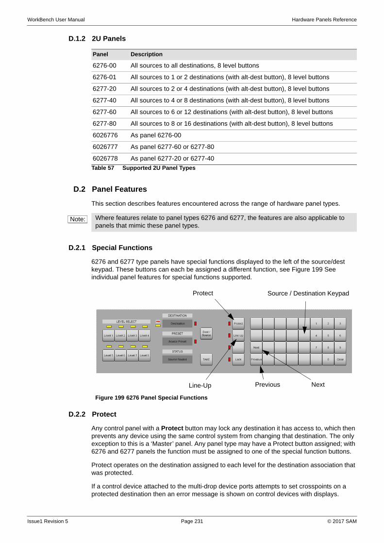
WorkBench User Manual Hardware Panels Reference
D.1.2 2U Panels
D.2 Panel Features
This section describes features encountered across the range of hardware panel types.
D.2.1 Special Functions
6276 and 6277 type panels have special functions displayed to the left of the source/dest keypad. These buttons can each be assigned a different function, see Figure 199 See individual panel features for special functions supported.
D.2.2 Protect
Any control panel with a Protect button may lock any destination it has access to, which then prevents any device using the same control system from changing that destination. The only exception to this is a ‘Master’ panel. Any panel type may have a Protect button assigned; with 6276 and 6277 panels the function must be assigned to one of the special function buttons.
Protect operates on the destination assigned to each level for the destination association that was protected.
If a control device attached to the multi-drop device ports attempts to set crosspoints on a protected destination then an error message is shown on control devices with displays.
Panel Description
6276-00 All sources to all destinations, 8 level buttons
6276-01 All sources to 1 or 2 destinations (with alt-dest button), 8 level buttons
6277-20 All sources to 2 or 4 destinations (with alt-dest button), 8 level buttons
6277-40 All sources to 4 or 8 destinations (with alt-dest button), 8 level buttons
6277-60 All sources to 6 or 12 destinations (with alt-dest button), 8 level buttons
6277-80 All sources to 8 or 16 destinations (with alt-dest button), 8 level buttons
6026776 As panel 6276-00
6026777 As panel 6277-60 or 6277-80
6026778 As panel 6277-20 or 6277-40
Table 57 Supported 2U Panel Types
Note: Where features relate to panel types 6276 and 6277, the features are also applicable to panels that mimic these panel types.
Figure 199 6276 Panel Special Functions
Line-Up
Protect Source / Destination Keypad
NextPrevious
Issue1 Revision 5 Page 231 © 2017 SAM
WorkBench User Manual Hardware Panels Reference
If they are assigned to the same destination, setting a protected destination causes protect button LEDs on other BPX type panels to flash.
D.2.3 Line-up
This is a continuous toggle (once a second) of the preset and program sources to the selected destination, allowing easy comparison of sources. This is only available on 6276 and 6277 panels using the special function buttons. Line-up of sources is selected as follows:
• Route source to be aligned to desired destination.
• Make sure the level of the sources to be aligned is the most significant active level.
• Select reference source as the preset source.
• Press LINE-UP button on panel. The LED associated with the LINE-UP button lights up to indicate that the button has been pressed.
• Press TAKE button of desired destination. The source routed toggles between the reference source and the source to be aligned.
• Line-up of sources on a destination is cancelled by pressing the LINE-UP button again. This cancels line-up altogether on the control device.
• The source being aligned is returned as the source routed to the destination being used and also the LED associated with the LINE-UP button is extinguished.
• Pressing another TAKE button on the same panel causes the original source to be routed to the previous destination and then start the line-up sequence on the new destination.
D.2.4 Next and Previous
Each time the NEXT or PREVIOUS button is pressed, the source or destination association number selected, depending on the active keypad, is increased or decreased. The panel displays are updated accordingly. These functions only work on 6276 and 6277 panels.
D.2.5 Alt-dest
ALT-DEST allows a 6277 multi-destination panel to access more destinations than are usually configured, that is, one per status display. When pressed, the panel changes control to the alternate set of assigned destination associations configured in the database. When the LED to the left of the ALT-DEST button is illuminated, the panel is then controlling the second set of destination associations assigned to the panel. This function must use a special function button.
D.2.6 Dest-ident
The DEST-IDENT button is used to identify the destination associations assigned to the TAKE buttons on a 6277 multi-destination panel. Pressing and holding down the DEST-IDENT button changes the STATUS to show the 8-character name for the assigned destination association for the current set of destination associations. This button is especially useful when an ALT-DEST button has been assigned.
D.2.7 Level Buttons
Many panel types have level buttons in their configuration. These allow ‘breakaway’ route selections to be made, that is, routes that are made by selecting parts of an association.
Each button operates in a toggle on/off manner with the level button active indicated by an illuminated button, or associated LED/lamp. The levels that each button controls are individually configurable.
Note: All control devices power-up with line-up inactive.
Issue1 Revision 5 Page 232 © 2017 SAM
WorkBench User Manual Hardware Panels Reference
D.2.8 Alt-lev
The Alternate level shift function is used on panels where there are more levels than level buttons, allowing individual control of all levels. It operates in a toggle on/off manner with an LED/lamp used to indicate the level shift - when the LED/lamp is off then the non-shifted levels are controllable and when the LED/lamp is on the shifted levels are controllable.
The level shift function is button programmable on all panel types (BPX and X-Y). Any source or destination button can be configured as a level shift button.
D.2.9 Clear
This key is used as a source preset or destination clear key and is generally assigned to the bottom right key on the keypad of a 6276 or 6277 panel.
D.2.10 Controllable Destinations
This applies to X-Y panels only. Any destination can be configured to be controllable (default) from a given X-Y panel. Routes may be viewed but cannot be changed.
D.2.11 Destination Keypads
All X-Y style panels have a destination keypad. This is either button-per-destination (BPD) as on 1U XY panels, or dial-up (multiple button presses) as on 6276 panels. These are configured in the database.
Press a destination button (BPD) or a sequence of buttons (dial-up) to select a destination association. The advantage of a dial-up keypad is that many more destinations may be accessed from the same size keypad.
The pressed button either illuminates if it has a valid associated destination association index, or has alphanumerics to display the name of the selected destination association.
On power-up no destination button is selected, so all destination buttons are extinguished, and any destination displays on X-Y panels are blank.
D.2.12 Source Keypads
All control panels have a source keypad. This is either a button-per-source (BPS) as on 1U panels or dial-up (multiple button presses) as on 6276/6277 panels. These are configured in the database.
Press a source button (BPS) or a sequence of buttons (dial-up) to select a source association. The advantage of a dial-up keypad is that many more sources may be accessed from the same size keypad.
The source keypads on 6276/6277 panels are used to pre-select sources, not route them. These panels have <TAKE> buttons to confirm the selections.
The pressed button either illuminates if it has a valid associated source association index, or has alphanumerics to display the name of the selected source association.
D.2.13 Panel Swap Mode
Panel Swap Mode is available for 6276 and 6277 panels. When activated in the database, it causes the taken source and the preselected source to swap, or interchange, and therefore allows the previously taken source to be re-routed with another TAKE. This could be considered to be an undo facility, for quickly reverting to the previous selection.
This feature is currently supported on a 2450 controller only.
Issue1 Revision 5 Page 233 © 2017 SAM
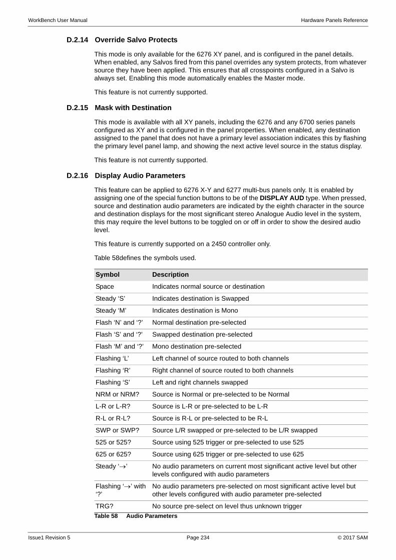
WorkBench User Manual Hardware Panels Reference
D.2.14 Override Salvo Protects
This mode is only available for the 6276 XY panel, and is configured in the panel details. When enabled, any Salvos fired from this panel overrides any system protects, from whatever source they have been applied. This ensures that all crosspoints configured in a Salvo is always set. Enabling this mode automatically enables the Master mode.
This feature is not currently supported.
D.2.15 Mask with Destination
This mode is available with all XY panels, including the 6276 and any 6700 series panels configured as XY and is configured in the panel properties. When enabled, any destination assigned to the panel that does not have a primary level association indicates this by flashing the primary level panel lamp, and showing the next active level source in the status display.
This feature is not currently supported.
D.2.16 Display Audio Parameters
This feature can be applied to 6276 X-Y and 6277 multi-bus panels only. It is enabled by assigning one of the special function buttons to be of the DISPLAY AUD type. When pressed, source and destination audio parameters are indicated by the eighth character in the source and destination displays for the most significant stereo Analogue Audio level in the system, this may require the level buttons to be toggled on or off in order to show the desired audio level.
This feature is currently supported on a 2450 controller only.
Table 58defines the symbols used.
Symbol Description
Space Indicates normal source or destination
Steady ‘S’ Indicates destination is Swapped
Steady ‘M’ Indicates destination is Mono
Flash ‘N’ and ‘?’ Normal destination pre-selected
Flash ‘S’ and ‘?’ Swapped destination pre-selected
Flash ‘M’ and ‘?’ Mono destination pre-selected
Flashing ‘L’ Left channel of source routed to both channels
Flashing ‘R’ Right channel of source routed to both channels
Flashing ‘S’ Left and right channels swapped
NRM or NRM? Source is Normal or pre-selected to be Normal
L-R or L-R? Source is L-R or pre-selected to be L-R
R-L or R-L? Source is R-L or pre-selected to be R-L
SWP or SWP? Source L/R swapped or pre-selected to be L/R swapped
525 or 525? Source using 525 trigger or pre-selected to use 525
625 or 625? Source using 625 trigger or pre-selected to use 625
Steady ‘’ No audio parameters on current most significant active level but other levels configured with audio parameters
Flashing ‘’ with ‘?’
No audio parameters pre-selected on most significant active level but other levels configured with audio parameter pre-selected
TRG? No source pre-select on level thus unknown trigger
Table 58 Audio Parameters
Issue1 Revision 5 Page 234 © 2017 SAM

WorkBench User Manual Hardware Panels Reference
AUP? No source pre-select on level thus unknown audio parameter
Symbol Description
Table 58 Audio Parameters
Issue1 Revision 5 Page 235 © 2017 SAM
WorkBench User Manual Hardware Panels Reference
D.2.17 Configure Audio Parameters
This feature can be applied to 6276 X-Y and 6277 multi-bus panels only. It is enabled by assigning one of the special function buttons to be of the <CONFIG AUD> type. When pressed, not only are the source and destination audio parameters indicated by the eighth character of the display, as in the previous table, but they may also be changed. When enabled this feature allows pre-selection of destination AUD parameters for stereo analogue audio levels. If panel is a Master 6276 X-Y then enabling this feature allows AUD parameters to be assigned to sources and destinations and allows trigger type to be assigned to sources.
This feature is currently supported on a 2450 controller only.
D.2.18 Override Inputs
Some panels allow a number of override inputs to momentarily override the current source routed to a destination with another source.
When all overrides are released the original source that was routed before any overrides were activated is restored. Shorting an override input pin to 0 V, activates the override.
Each override input can have any source assigned to it and can be assigned to operate on any level. If more than one override input is active on a panel, then the lowest number override has priority.
When a destination is overridden no other crosspoint can be set on that destination by any means unless it is a higher priority override.
The maximum number of overrides available to a panel is 16. Current supported panel s have 8 or 12 overrides available.
D.2.19 Panel Lock
Most panels have the ability to disable the takes, keypads and TAKE keys.
This can be done either using a panel lock button, or by connecting a key switch or similar to the remote panel disable input.
Lock Button
The position of the panel lock button is set in the database configuration. It will also have an associated LED/lamp.
Toggling the Lock button changes the panel between locked and unlocked with its associated LED/lamp illuminating to indicate the state (ON = panel locked).
Remote Panel Disable Input
The remote panel disable input is enabled in the database panel configuration.
The system detects a locked panel through pin 8 of the Overrride (AUX) inputs located on the socket connector on the rear of the panel.
To lock the panel pin 8 needs to be connected to 0 V.
Operation
When the panel is locked, the associated lock button LED/lamp is illuminated, and for panels with alphanumeric displays, the Preset display indicates ‘LOCKED!’ The panel is thus prevented from pre-selecting and routing sources.
The Panel Disable Input takes priority over the lock button on the front, and whilst the Panel Disable Input is active the Lock button has no action.
Issue1 Revision 5 Page 236 © 2017 SAM
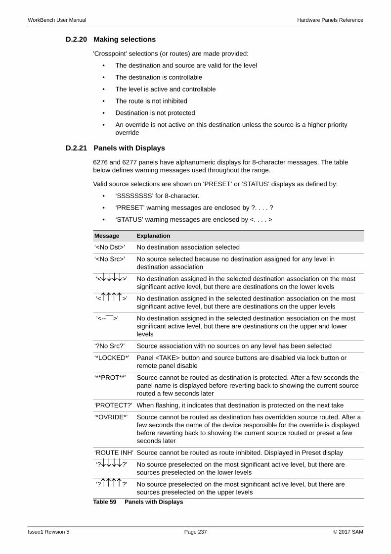
WorkBench User Manual Hardware Panels Reference
D.2.20 Making selections
'Crosspoint' selections (or routes) are made provided:
• The destination and source are valid for the level
• The destination is controllable
• The level is active and controllable
• The route is not inhibited
• Destination is not protected
• An override is not active on this destination unless the source is a higher priority override
D.2.21 Panels with Displays
6276 and 6277 panels have alphanumeric displays for 8-character messages. The table below defines warning messages used throughout the range.
Valid source selections are shown on ‘PRESET’ or ‘STATUS’ displays as defined by:
• ‘SSSSSSSS’ for 8-character.
• ‘PRESET’ warning messages are enclosed by ?. . . . ?
• ‘STATUS’ warning messages are enclosed by <. . . . >
Message Explanation
‘<No Dst>’ No destination association selected
‘<No Src>’ No source selected because no destination assigned for any level in destination association
‘<>’ No destination assigned in the selected destination association on the most significant active level, but there are destinations on the lower levels
‘<>’ No destination assigned in the selected destination association on the most significant active level, but there are destinations on the upper levels
‘<--¯¯>’ No destination assigned in the selected destination association on the most significant active level, but there are destinations on the upper and lower levels
‘?No Src?’ Source association with no sources on any level has been selected
‘*LOCKED*’ Panel <TAKE> button and source buttons are disabled via lock button or remote panel disable
‘**PROT**’ Source cannot be routed as destination is protected. After a few seconds the panel name is displayed before reverting back to showing the current source routed a few seconds later
‘PROTECT?’ When flashing, it indicates that destination is protected on the next take
‘*OVRIDE*’ Source cannot be routed as destination has overridden source routed. After a few seconds the name of the device responsible for the override is displayed before reverting back to showing the current source routed or preset a few seconds later
‘ROUTE INH’ Source cannot be routed as route inhibited. Displayed in Preset display
‘??’ No source preselected on the most significant active level, but there are sources preselected on the lower levels
‘??’ No source preselected on the most significant active level, but there are sources preselected on the upper levels
Table 59 Panels with Displays
Issue1 Revision 5 Page 237 © 2017 SAM

WorkBench User Manual Hardware Panels Reference
The brightness of displays on applicable panels may be changed by reconfiguring the database. It is not possible to have different brightness levels for different displays on the same panel.
D.3 Audio Modify/Video Reference Operations
D.3.1 Common Rules
While ‘config AUD parameters’ is enabled then only AUD parameters can be pre-selected (i.e. sources and destinations cannot be dialled up). Press <CLEAR>, while in this mode to return the panel to its previous state.
If the ‘display audio parameters’ function is disabled then full 8-character names is displayed with no AUD parameter, even if the first level is Analogue Audio.
Selecting ‘display audio’ function results in the eighth character of the displays showing the AUD parameter assigned for the most significant active level.
Assuming ‘display audio parameters’ is enabled then:
The eighth character in PRESET and STATUS displays is:
• Steady (non-flashing) when source AUD parameter is NORMAL
• Flashing when source AUD parameter is NOT NORMAL, for example, SWAP
Eighth character in PRESET window displays AUD parameter of the pre-selected source displayed for the most significant active level in the system.
Eighth character in STATUS displays AUD parameter of combined source and destination taken for the most significant active level.
Eighth character in DESTINATION displays the destination AUD parameter of the destination displayed for the most significant active level in the system.
If <CONFIG AUDIO> is pressed to enable configuration of AUD parameters and no buttons are pressed within a 1 minute time-out period then this function is automatically disabled and the panel is returned to its previous state.
Enabling configuration of audio parameters always results in ‘display audio parameters’ being enabled.
The 'N' character to denote Normal is only used in AUD parameter pre-selecting. Usually eighth character is left blank to denote Normal.
‘??’ No source preselected on the most significant active level, but there are sources preselected on the higher and lower levels
‘SALVO’ Displayed in STATUS or IN-USE displays to indicate that a salvo has been preselected
‘NO XPT!’ Error message displayed in STATUS or IN-USE to indicate that a crosspoint cannot be set as card not present
‘LEV CON’ Error message displayed in STATUS or IN-USE to indicate that a crosspoint was not made on a level because the level was not controllable from that panel
‘DST CON’ Error message displayed in STATUS or IN-USE to indicate that a crosspoint was not made because the X-Y panel attempting to set it is not allowed to control the destination
Message Explanation
Table 59 Panels with Displays
Issue1 Revision 5 Page 238 © 2017 SAM
WorkBench User Manual Hardware Panels Reference
If pre-selected route is found to be inhibited (from either editable route inhibit table or internal system inhibit table) then the destination AUD parameter pre-selected is thrown away.
If a route is protected then AUD parameters and trigger type cannot be changed.
D.3.2 Rules for 6276 X-Y Panels (not designated master)
Only Destination AUD parameters can be assigned from this panel type.
Eighth character in DESTINATION display is also used to show the pre-selected destination AUD parameter when character alternating with '?'.
Enabling configuration of AUD parameters by pressing <CONFIG AUDIO> always results in selector LED being lit against DESTINATION display.
Operation 1:
Press <DISPLAY AUDIO> to enable audio parameters to display (optional).
Select DESTINATION display.
Dial up destination (for example, VT 3)
Press <CONFIG AUDIO> (selector LED lit against DESTINATION display) followed by the required AUD parameter. The pre-selected AUD parameter is displayed (flashing alternately with '?') in the eighth character of the DESTINATION display.
Press <TAKE> to:
• Assign AUD parameter to destination
• Update eighth character of DESTINATION display to indicate new AUD parameter
• Update eighth character of STATUS display with combined source and destination AUD parameter
• Auto cancel ‘config AUD parameters’ mode
Operation 2:
Press <DISPLAY AUDIO> to enable audio parameters to display (optional).
Select DESTINATION display (selector LED lit against DESTINATION display)
Dial up destination (for example, VT 3)
Select PRESET display (selector LED lit against PRESET display)
Dial up a source (for example, VT 7)
Press <CONFIG AUDIO> (selector LED lit against DESTINATION display) followed by an AUD parameter. The pre-selected AUD parameter is displayed (flashing alternately with '?') in the eighth character of the DESTINATION display.
Press <TAKE> to:
• Assign AUD parameter to destination
• Update eighth character of DESTINATION display to indicate new AUD parameter
• Update eighth character of STATUS display with combined source and destination AUD parameter
• Auto cancel ‘config AUD parameters’ mode
Issue1 Revision 5 Page 239 © 2017 SAM
WorkBench User Manual Hardware Panels Reference
D.3.3 Rules for 6277 Multi-output Panels
Only Destination AUD parameters can be assigned from this panel type.
When DEST-IDENT activated the eighth character in STATUS displays AUD parameter of the destination for the most significant active level in the system.
Eighth character in PRESET display normally displays AUD parameter of the pre-selected source displayed for the most significant active level in the system. It is also used to show the pre-selected destination AUD parameter.
Operation 1:
Press <DISPLAY AUDIO> to enable audio parameters to display (optional).
Clear PRESET display.
Press <CONFIG AUDIO> and select an AUD parameter. An 8-character name is displayed in the PRESET display to indicate destination AUD parameter pre-selected.
Press <TAKE> to:
• Assign AUD parameter to destination
• Update eighth character of STATUS display with combined source and destination AUD parameter
• Auto cancel ‘config AUD parameters’ mode and blank PRESET display
Operation 2:
Press <DISPLAY AUDIO> to enable audio parameters to display (optional).
Dial up source in PRESET display.
Press <CONFIG AUDIO> and select an AUD parameter. The pre-selected AUD parameter is displayed (flashing alternately with '?') in the eighth character of the PRESET display.
Press <TAKE> to:
• Assign AUD parameter to destination
• Update eighth character of STATUS display with combined source and destination AUD parameter
• Revert to showing source AUD parameter in eighth character of PRESET display
• Auto cancel ‘config AUD parameters’ mode
Issue1 Revision 5 Page 240 © 2017 SAM
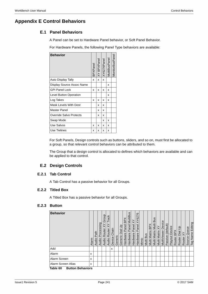
WorkBench User Manual Control Behaviors
Appendix E Control Behaviors
E.1 Panel Behaviors
A Panel can be set to Hardware Panel behavior, or Soft Panel Behavior.
For Hardware Panels, the following Panel Type behaviors are available:
For Soft Panels, Design controls such as buttons, sliders, and so on, must first be allocated to a group, so that relevant control behaviors can be attributed to them.
The Group that a design control is allocated to defines which behaviors are available and can be applied to that control.
E.2 Design Controls
E.2.1 Tab Control
A Tab Control has a passive behavior for all Groups.
E.2.2 Titled Box
A Titled Box has a passive behavior for all Groups.
E.2.3 Button
Behavior
BP
XP
anel
XY
BP
XP
an
el
XY
627
6P
an
el
Mu
ltiB
usP
an
el
Mo
nito
rBus
Pan
el
Auto Display Tally x x x
Display Source Assoc Name x
GPI Panel Lock x x x x
Level Button Operation x
Log Takes x x x x
Mask Levels With Dest x x
Master Panel x x
Override Salvo Protects x x
Swap Mode x x
Use Salvos x x x x
Use Tielines x x x x
Behavior
Ala
rm
Aud
io P
ath
Aud
io P
roce
ssin
g
Aud
io R
ou
ter
XY
Gro
up
Aud
io R
ou
ter
XY
Tra
ck
De
vice
Ch
ain
Ge
ne
ric
Ge
ne
ric D
ial U
p
Ha
rdw
are
Pa
ne
l BP
X
Har
dwar
e P
anel
Mul
tiBus
Ha
rdw
are
Pa
ne
l XY
Ha
rdw
are
Pa
nel
XY
62
76
Mim
ic
Mu
lti B
us
Mu
lti M
atrix
BP
X
Mu
lti M
atrix
Mul
ti B
us
Mu
lti M
atrix
XY
Mu
ltiV
iew
er D
evi
ce
Pas
sive
(de
fau
lt)
Pla
you
t D
evi
ce
Ro
ute
r B
PX
Ro
ute
r D
ial U
p
Ro
ute
r X
Y
Sou
rce
Que
ue
Tag
Na
me
Edi
ting
Add x
Alarm x
Alarm Screen x
Alarm Screen Alias x
Table 60 Button Behaviors
Issue1 Revision 5 Page 241 © 2017 SAM
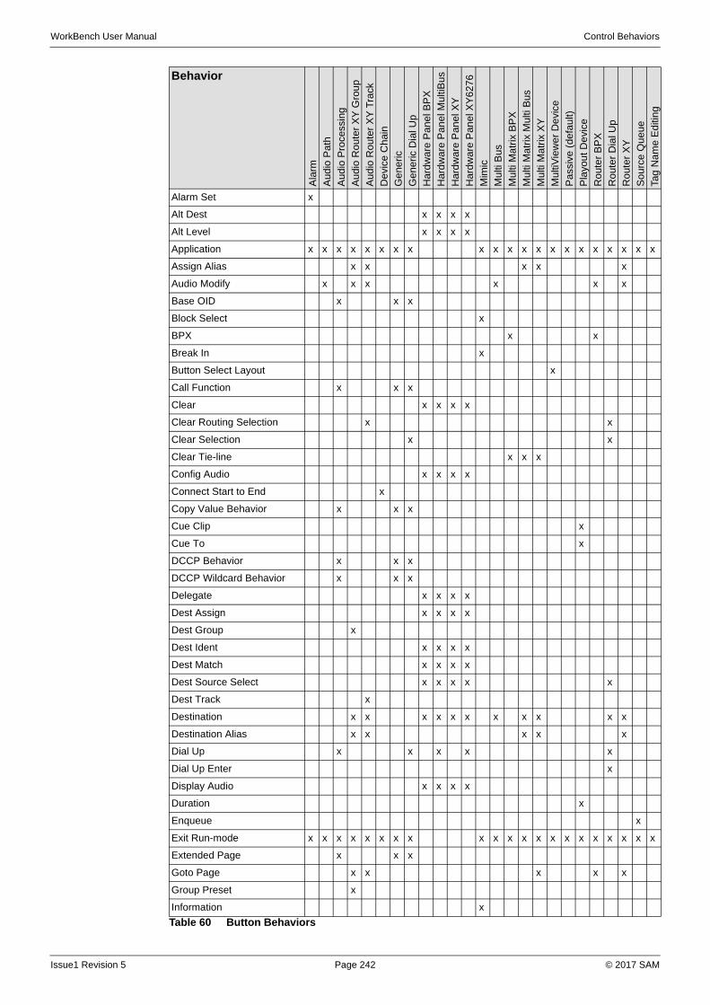
WorkBench User Manual Control Behaviors
Alarm Set x
Alt Dest x x x x
Alt Level x x x x
Application x x x x x x x x x x x x x x x x x x x x x
Assign Alias x x x x x
Audio Modify x x x x x x
Base OID x x x
Block Select x
BPX x x
Break In x
Button Select Layout x
Call Function x x x
Clear x x x x
Clear Routing Selection x x
Clear Selection x x
Clear Tie-line x x x
Config Audio x x x x
Connect Start to End x
Copy Value Behavior x x x
Cue Clip x
Cue To x
DCCP Behavior x x x
DCCP Wildcard Behavior x x x
Delegate x x x x
Dest Assign x x x x
Dest Group x
Dest Ident x x x x
Dest Match x x x x
Dest Source Select x x x x x
Dest Track x
Destination x x x x x x x x x x x
Destination Alias x x x x x
Dial Up x x x x x
Dial Up Enter x
Display Audio x x x x
Duration x
Enqueue x
Exit Run-mode x x x x x x x x x x x x x x x x x x x x x
Extended Page x x x
Goto Page x x x x x
Group Preset x
Information x
Behavior
Ala
rm
Au
dio
Pa
th
Au
dio
Pro
cess
ing
Au
dio
Ro
uter
XY
Gro
up
Au
dio
Ro
uter
XY
Tra
ck
De
vice
Ch
ain
Ge
ner
ic
Ge
ner
ic D
ial U
p
Ha
rdw
are
Pan
el B
PX
Ha
rdw
are
Pan
el M
ulti
Bu
s
Ha
rdw
are
Pan
el X
Y
Ha
rdw
are
Pan
el X
Y6
276
Mim
ic
Mu
lti B
us
Mu
lti M
atr
ix B
PX
Mu
lti M
atr
ix M
ulti
Bu
s
Mu
lti M
atr
ix X
Y
Mu
ltiV
iew
er
De
vice
Pa
ssiv
e (
de
fau
lt)
Pla
you
t D
evi
ce
Ro
ute
r B
PX
Ro
ute
r D
ial U
p
Ro
ute
r X
Y
So
urc
e Q
ue
ue
Tag
Na
me
Ed
itin
g
Table 60 Button Behaviors
Issue1 Revision 5 Page 242 © 2017 SAM
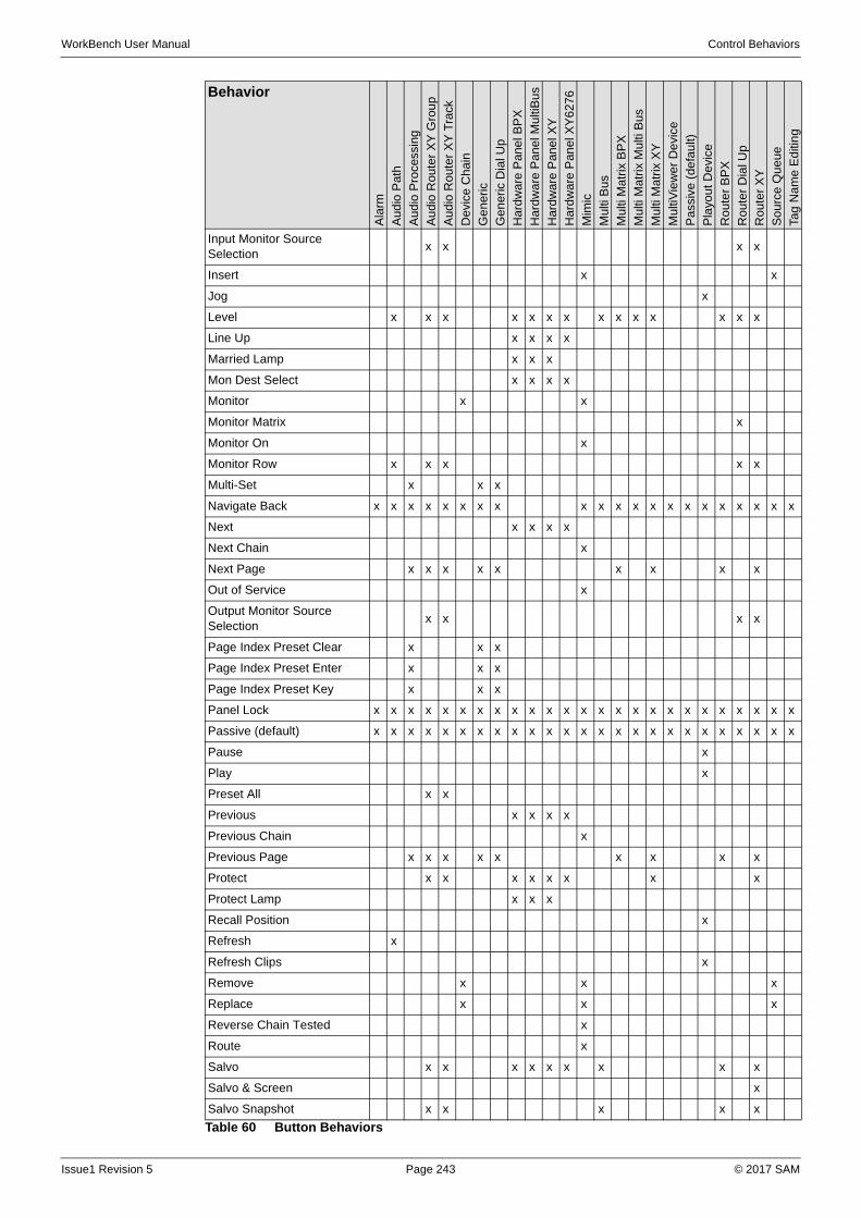
WorkBench User Manual Control Behaviors
Input Monitor Source Selection
x x x x
Insert x x
Jog x
Level x x x x x x x x x x x x x x
Line Up x x x x
Married Lamp x x x
Mon Dest Select x x x x
Monitor x x
Monitor Matrix x
Monitor On x
Monitor Row x x x x x
Multi-Set x x x
Navigate Back x x x x x x x x x x x x x x x x x x x x x
Next x x x x
Next Chain x
Next Page x x x x x x x x x
Out of Service x
Output Monitor Source Selection
x x x x
Page Index Preset Clear x x x
Page Index Preset Enter x x x
Page Index Preset Key x x x
Panel Lock x x x x x x x x x x x x x x x x x x x x x x x x x
Passive (default) x x x x x x x x x x x x x x x x x x x x x x x x x
Pause x
Play x
Preset All x x
Previous x x x x
Previous Chain x
Previous Page x x x x x x x x x
Protect x x x x x x x x
Protect Lamp x x x
Recall Position x
Refresh x
Refresh Clips x
Remove x x x
Replace x x x
Reverse Chain Tested x
Route x
Salvo x x x x x x x x x
Salvo & Screen x
Salvo Snapshot x x x x x
Behavior
Ala
rm
Au
dio
Pa
th
Au
dio
Pro
cess
ing
Au
dio
Ro
uter
XY
Gro
up
Au
dio
Ro
uter
XY
Tra
ck
De
vice
Ch
ain
Ge
ner
ic
Ge
ner
ic D
ial U
p
Ha
rdw
are
Pan
el B
PX
Ha
rdw
are
Pan
el M
ulti
Bu
s
Ha
rdw
are
Pan
el X
Y
Ha
rdw
are
Pan
el X
Y6
276
Mim
ic
Mu
lti B
us
Mu
lti M
atr
ix B
PX
Mu
lti M
atr
ix M
ulti
Bu
s
Mu
lti M
atr
ix X
Y
Mu
ltiV
iew
er
De
vice
Pa
ssiv
e (
de
fau
lt)
Pla
you
t D
evi
ce
Ro
ute
r B
PX
Ro
ute
r D
ial U
p
Ro
ute
r X
Y
So
urc
e Q
ue
ue
Tag
Na
me
Ed
itin
g
Table 60 Button Behaviors
Issue1 Revision 5 Page 243 © 2017 SAM
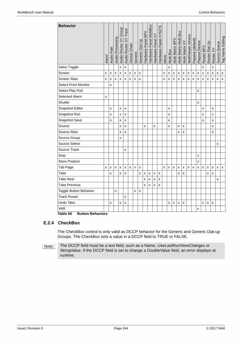
WorkBench User Manual Control Behaviors
E.2.4 CheckBox
The CheckBox control is only valid as DCCP behavior for the Generic and Generic Dial-up Groups. The CheckBox sets a value in a DCCP field to TRUE or FALSE.
Salvo Toggle x x x x x
Screen x x x x x x x x x x x x x x x x x x x x x
Screen Alias x x x x x x x x x x x x x x x x x x x x x
Select From Monitor x
Select Play Port x
Selected Alarm x
Shuttle x
Snapshot Editor x x x x x x
Snapshot Run x x x x x x
Snapshot Save x x x x x x
Source x x x x x x x x
Source Alias x x x x x
Source Group x
Source Select x
Source Track x
Stop x
Store Position x
Tab Page x x x x x x x x x x x x x x x x x x x x x
Take x x x x x x x x x x x x
Take Next x x x x x
Take Previous x x x x
Toggle Button Behavior x x x
Track Preset x
Undo Take x x x x x x x x x x
VAR x
Behavior
Ala
rm
Au
dio
Pa
th
Au
dio
Pro
cess
ing
Au
dio
Ro
uter
XY
Gro
up
Au
dio
Ro
uter
XY
Tra
ck
De
vice
Ch
ain
Ge
ner
ic
Ge
ner
ic D
ial U
p
Ha
rdw
are
Pan
el B
PX
Ha
rdw
are
Pan
el M
ulti
Bu
s
Ha
rdw
are
Pan
el X
Y
Ha
rdw
are
Pan
el X
Y6
276
Mim
ic
Mu
lti B
us
Mu
lti M
atr
ix B
PX
Mu
lti M
atr
ix M
ulti
Bu
s
Mu
lti M
atr
ix X
Y
Mu
ltiV
iew
er
De
vice
Pa
ssiv
e (
de
fau
lt)
Pla
you
t D
evi
ce
Ro
ute
r B
PX
Ro
ute
r D
ial U
p
Ro
ute
r X
Y
So
urc
e Q
ue
ue
Tag
Na
me
Ed
itin
g
Table 60 Button Behaviors
Note: The DCCP field must be a text field, such as a Name, UseLastRunViewChanges or StringValue. If the DCCP field is set to change a DoubleValue field, an error displays at runtime.
Issue1 Revision 5 Page 244 © 2017 SAM
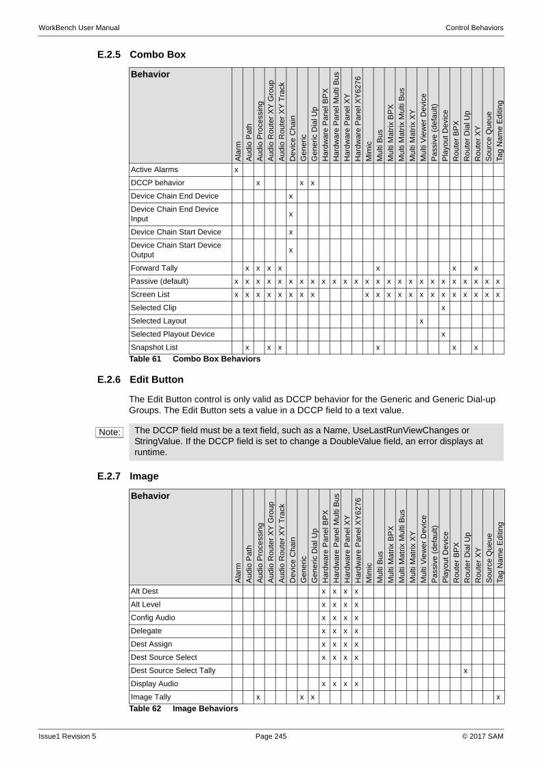
WorkBench User Manual Control Behaviors
E.2.5 Combo Box
E.2.6 Edit Button
The Edit Button control is only valid as DCCP behavior for the Generic and Generic Dial-up Groups. The Edit Button sets a value in a DCCP field to a text value.
E.2.7 Image
Behavior
Ala
rm
Au
dio
Pa
th
Au
dio
Pro
cess
ing
Au
dio
Ro
uter
XY
Gro
up
Au
dio
Ro
uter
XY
Tra
ck
De
vice
Ch
ain
Ge
ner
ic
Ge
ner
ic D
ial U
p
Ha
rdw
are
Pan
el B
PX
Ha
rdw
are
Pan
el M
ulti
Bus
Ha
rdw
are
Pan
el X
Y
Ha
rdw
are
Pan
el X
Y6
276
Mim
ic
Mu
lti B
us
Mu
lti M
atr
ix B
PX
Mu
lti M
atr
ix M
ulti
Bu
s
Mu
lti M
atr
ix X
Y
Mu
lti V
iew
er
De
vice
Pa
ssiv
e (
de
fau
lt)
Pla
you
t D
evi
ce
Ro
ute
r B
PX
Ro
ute
r D
ial U
p
Ro
ute
r X
Y
So
urc
e Q
ue
ue
Tag
Na
me
Ed
itin
g
Active Alarms x
DCCP behavior x x x
Device Chain End Device x
Device Chain End Device Input
x
Device Chain Start Device x
Device Chain Start Device Output
x
Forward Tally x x x x x x x
Passive (default) x x x x x x x x x x x x x x x x x x x x x x x x x
Screen List x x x x x x x x x x x x x x x x x x x x x
Selected Clip x
Selected Layout x
Selected Playout Device x
Snapshot List x x x x x x
Table 61 Combo Box Behaviors
Note: The DCCP field must be a text field, such as a Name, UseLastRunViewChanges or StringValue. If the DCCP field is set to change a DoubleValue field, an error displays at runtime.
Behavior
Ala
rm
Aud
io P
ath
Aud
io P
roce
ssin
g
Aud
io R
ou
ter
XY
Gro
up
Aud
io R
ou
ter
XY
Tra
ck
Dev
ice
Ch
ain
Ge
ne
ric
Ge
ne
ric D
ial U
p
Har
dw
are
Pa
ne
l BP
X
Har
dwar
e P
anel
Mul
ti B
us
Har
dw
are
Pa
ne
l XY
Har
dw
are
Pa
nel
XY
62
76
Mim
ic
Mu
lti B
us
Mu
lti M
atrix
BP
X
Mu
lti M
atrix
Mul
ti B
us
Mu
lti M
atrix
XY
Mu
lti V
iew
er
Dev
ice
Pas
sive
(de
fau
lt)
Pla
yout
De
vice
Rou
ter
BP
X
Rou
ter
Dia
l Up
Rou
ter
XY
Sou
rce
Que
ue
Tag
Na
me
Edi
ting
Alt Dest x x x x
Alt Level x x x x
Config Audio x x x x
Delegate x x x x
Dest Assign x x x x
Dest Source Select x x x x
Dest Source Select Tally x
Display Audio x x x x
Image Tally x x x x
Table 62 Image Behaviors
Issue1 Revision 5 Page 245 © 2017 SAM
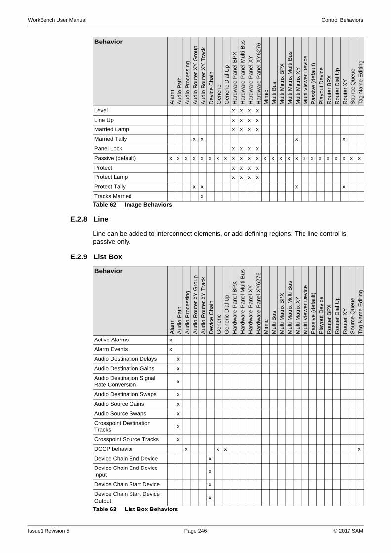
WorkBench User Manual Control Behaviors
E.2.8 Line
Line can be added to interconnect elements, or add defining regions. The line control is passive only.
E.2.9 List Box
Level x x x x
Line Up x x x x
Married Lamp x x x x
Married Tally x x x x
Panel Lock x x x x
Passive (default) x x x x x x x x x x x x x x x x x x x x x x x x x
Protect x x x x
Protect Lamp x x x x
Protect Tally x x x x
Tracks Married x
Behavior
Ala
rm
Au
dio
Pa
th
Au
dio
Pro
cess
ing
Au
dio
Ro
uter
XY
Gro
up
Au
dio
Ro
uter
XY
Tra
ck
De
vice
Ch
ain
Ge
ner
ic
Ge
ner
ic D
ial U
p
Ha
rdw
are
Pan
el B
PX
Ha
rdw
are
Pan
el M
ulti
Bus
Ha
rdw
are
Pan
el X
Y
Ha
rdw
are
Pan
el X
Y6
276
Mim
ic
Mu
lti B
us
Mu
lti M
atr
ix B
PX
Mu
lti M
atr
ix M
ulti
Bu
s
Mu
lti M
atr
ix X
Y
Mu
lti V
iew
er D
evi
ce
Pa
ssiv
e (
de
fau
lt)
Pla
you
t D
evi
ce
Ro
ute
r B
PX
Ro
ute
r D
ial U
p
Ro
ute
r X
Y
So
urc
e Q
ue
ue
Tag
Na
me
Ed
itin
g
Table 62 Image Behaviors
Behavior
Ala
rm
Au
dio
Pa
th
Au
dio
Pro
cess
ing
Au
dio
Ro
ute
r X
Y G
roup
Au
dio
Ro
ute
r X
Y T
rack
De
vice
Cha
in
Ge
ner
ic
Ge
ner
ic D
ial U
p
Har
dwar
e P
ane
l BP
X
Ha
rdw
are
Pa
ne
l Mu
lti B
us
Har
dwar
e P
ane
l XY
Har
dwar
e P
ane
l XY
6276
Mim
ic
Mu
lti B
us
Mu
lti M
atr
ix B
PX
Mu
lti M
atr
ix M
ulti
Bu
s
Mu
lti M
atr
ix X
Y
Mu
lti V
iew
er
De
vice
Pa
ssiv
e (
de
fau
lt)
Pla
you
t D
evi
ce
Ro
ute
r B
PX
Ro
ute
r D
ial U
p
Ro
ute
r X
Y
So
urc
e Q
ue
ue
Tag
Na
me
Ed
itin
g
Active Alarms x
Alarm Events x
Audio Destination Delays x
Audio Destination Gains x
Audio Destination Signal Rate Conversion
x
Audio Destination Swaps x
Audio Source Gains x
Audio Source Swaps x
Crosspoint Destination Tracks
x
Crosspoint Source Tracks x
DCCP behavior x x x x
Device Chain End Device x
Device Chain End Device Input
x
Device Chain Start Device x
Device Chain Start Device Output
x
Table 63 List Box Behaviors
Issue1 Revision 5 Page 246 © 2017 SAM
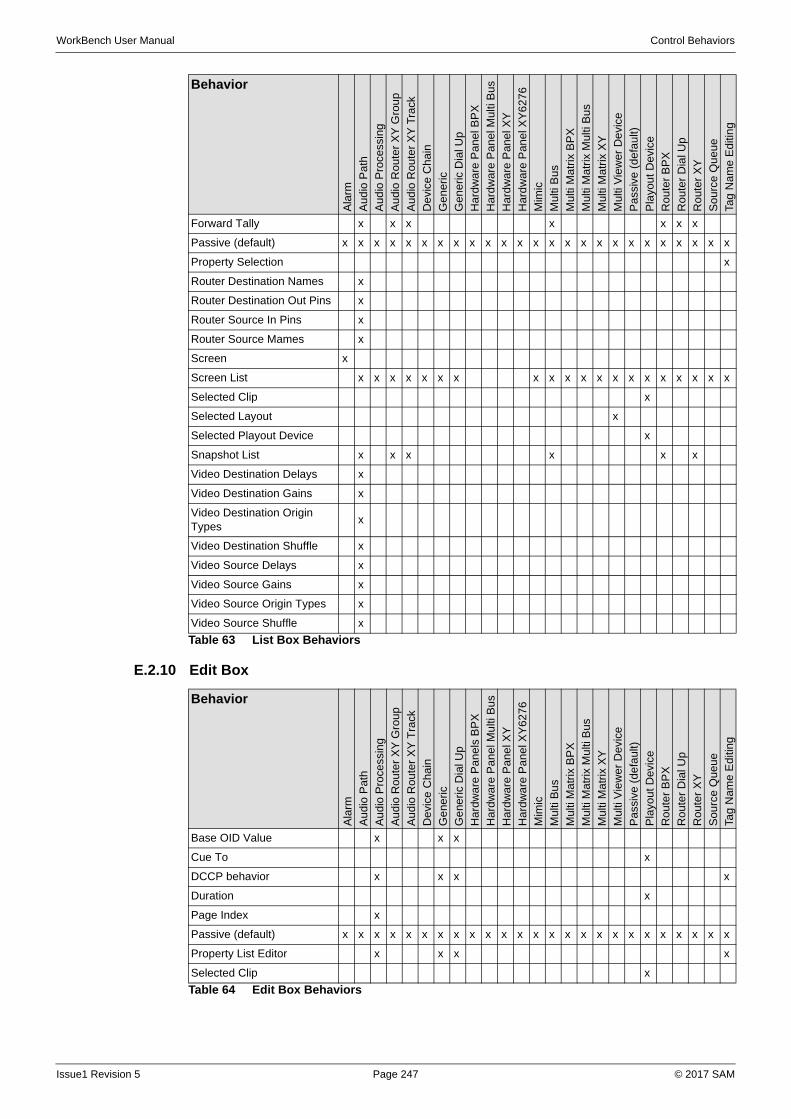
WorkBench User Manual Control Behaviors
E.2.10 Edit Box
Forward Tally x x x x x x x
Passive (default) x x x x x x x x x x x x x x x x x x x x x x x x x
Property Selection x
Router Destination Names x
Router Destination Out Pins x
Router Source In Pins x
Router Source Mames x
Screen x
Screen List x x x x x x x x x x x x x x x x x x x x
Selected Clip x
Selected Layout x
Selected Playout Device x
Snapshot List x x x x x x
Video Destination Delays x
Video Destination Gains x
Video Destination Origin Types
x
Video Destination Shuffle x
Video Source Delays x
Video Source Gains x
Video Source Origin Types x
Video Source Shuffle x
Behavior
Ala
rm
Au
dio
Pa
th
Au
dio
Pro
cess
ing
Au
dio
Ro
uter
XY
Gro
up
Au
dio
Ro
uter
XY
Tra
ck
De
vice
Ch
ain
Ge
ner
ic
Ge
ner
ic D
ial U
p
Ha
rdw
are
Pan
el B
PX
Ha
rdw
are
Pan
el M
ulti
Bus
Ha
rdw
are
Pan
el X
Y
Ha
rdw
are
Pan
el X
Y6
276
Mim
ic
Mu
lti B
us
Mu
lti M
atr
ix B
PX
Mu
lti M
atr
ix M
ulti
Bu
s
Mu
lti M
atr
ix X
Y
Mu
lti V
iew
er D
evi
ce
Pa
ssiv
e (
de
fau
lt)
Pla
you
t D
evi
ce
Ro
ute
r B
PX
Ro
ute
r D
ial U
p
Ro
ute
r X
Y
So
urc
e Q
ue
ue
Tag
Na
me
Ed
itin
g
Table 63 List Box Behaviors
Behavior
Ala
rm
Au
dio
Pat
h
Au
dio
Pro
cess
ing
Au
dio
Ro
ute
r X
Y G
rou
p
Au
dio
Ro
ute
r X
Y T
rack
Dev
ice
Cha
in
Ge
neri
c
Ge
neri
c D
ial U
p
Ha
rdw
are
Pa
ne
ls B
PX
Ha
rdw
are
Pa
ne
l Mu
lti B
us
Ha
rdw
are
Pa
ne
l XY
Ha
rdw
are
Pa
ne
l XY
62
76
Mim
ic
Mul
ti B
us
Mul
ti M
atr
ix B
PX
Mul
ti M
atr
ix M
ulti
Bu
s
Mul
ti M
atr
ix X
Y
Mul
ti V
iew
er
Dev
ice
Pa
ssiv
e (
de
faul
t)
Pla
you
t D
evic
e
Rou
ter
BP
X
Rou
ter
Dia
l Up
Rou
ter
XY
So
urc
e Q
ueu
e
Tag
Nam
e E
diti
ng
Base OID Value x x x
Cue To x
DCCP behavior x x x x
Duration x
Page Index x
Passive (default) x x x x x x x x x x x x x x x x x x x x x x x x x
Property List Editor x x x x
Selected Clip x
Table 64 Edit Box Behaviors
Issue1 Revision 5 Page 247 © 2017 SAM
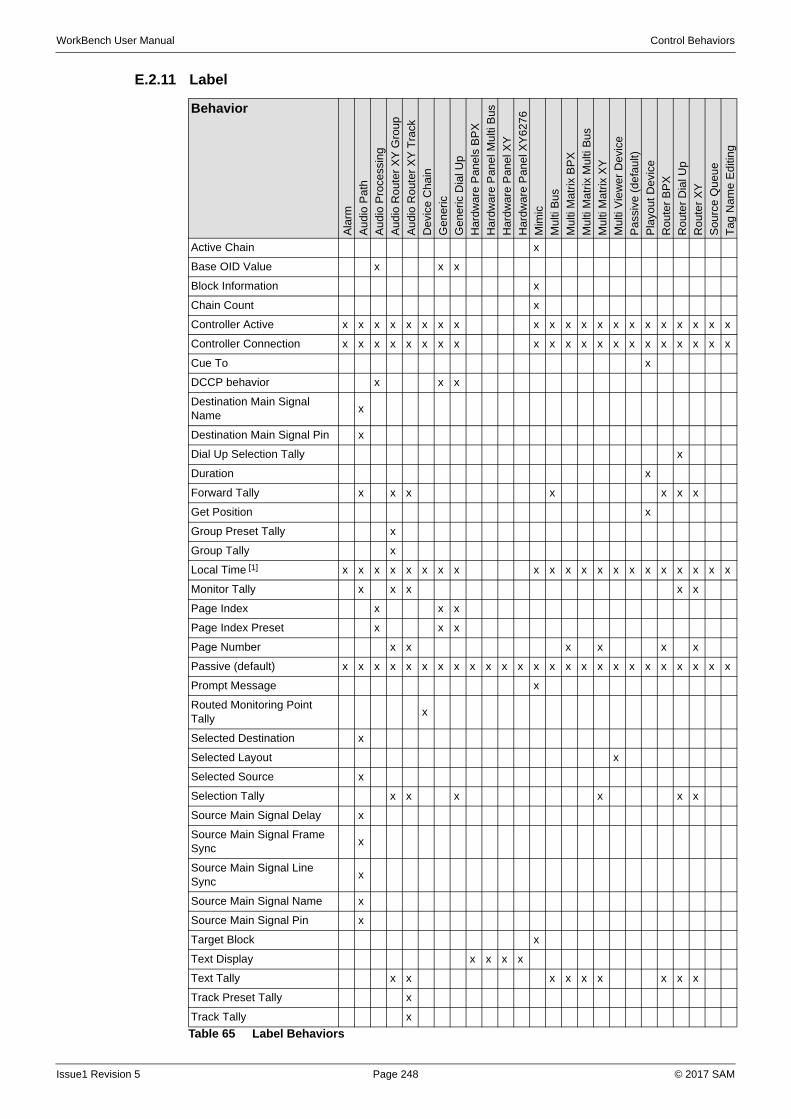
WorkBench User Manual Control Behaviors
E.2.11 Label
Behavior
Ala
rm
Au
dio
Pa
th
Au
dio
Pro
cess
ing
Au
dio
Ro
uter
XY
Gro
up
Au
dio
Ro
uter
XY
Tra
ck
De
vice
Ch
ain
Ge
ner
ic
Ge
ner
ic D
ial U
p
Har
dwar
e P
anel
s B
PX
Ha
rdw
are
Pan
el M
ulti
Bus
Ha
rdw
are
Pan
el X
Y
Ha
rdw
are
Pan
el X
Y6
276
Mim
ic
Mu
lti B
us
Mu
lti M
atr
ix B
PX
Mu
lti M
atr
ix M
ulti
Bu
s
Mu
lti M
atr
ix X
Y
Mu
lti V
iew
er
De
vice
Pa
ssiv
e (
de
fau
lt)
Pla
you
t D
evi
ce
Ro
ute
r B
PX
Ro
ute
r D
ial U
p
Ro
ute
r X
Y
So
urc
e Q
ue
ue
Ta
g N
ame
Ed
itin
g
Active Chain x
Base OID Value x x x
Block Information x
Chain Count x
Controller Active x x x x x x x x x x x x x x x x x x x x x
Controller Connection x x x x x x x x x x x x x x x x x x x x x
Cue To x
DCCP behavior x x x
Destination Main Signal Name
x
Destination Main Signal Pin x
Dial Up Selection Tally x
Duration x
Forward Tally x x x x x x x
Get Position x
Group Preset Tally x
Group Tally x
Local Time [1] x x x x x x x x x x x x x x x x x x x x x
Monitor Tally x x x x x
Page Index x x x
Page Index Preset x x x
Page Number x x x x x x
Passive (default) x x x x x x x x x x x x x x x x x x x x x x x x x
Prompt Message x
Routed Monitoring Point Tally
x
Selected Destination x
Selected Layout x
Selected Source x
Selection Tally x x x x x x
Source Main Signal Delay x
Source Main Signal Frame Sync
x
Source Main Signal Line Sync
x
Source Main Signal Name x
Source Main Signal Pin x
Target Block x
Text Display x x x x
Text Tally x x x x x x x x x
Track Preset Tally x
Track Tally x
Table 65 Label Behaviors
Issue1 Revision 5 Page 248 © 2017 SAM

WorkBench User Manual Control Behaviors
E.2.12 Composite Slider
The Composite Slider control is only valid as DCCP behavior for the Generic and Generic Dial Up Groups.
E.2.13 Slider
The Slider control is only valid as DCCP behavior for the Generic and Generic Dial Up Groups.
E.2.14 Up Down
The Up Down control is only valid as DCCP behavior for the Generic and Generic Dial Up Groups.
E.2.15 Hyperion Thumbnail
The Hyperion Thumbnail control is valid for all Groups.
E.2.16 Jog Shuttle
The Jog Shuttle control is only valid for the Playout Device Group. The available behaviors are:
• Cue Clip
• Cue To
• Jog
• Pause
• Play
• Shuttle
• Stop
• VAR
E.2.17 List Buttons
The List Buttons control is only valid as DCCP behavior for the Generic and Generic Dial Up Groups.
E.2.18 Media Player
The Media Player control is valid for all Groups except Hardware.
Undo Tally x x x x x x x
Version Info x x x x x x x x x x x x x x x x x x x x x
[1] Pre-defined times, or Microsoft custom date and time format strings.
Behavior
Ala
rm
Au
dio
Pa
th
Au
dio
Pro
cess
ing
Au
dio
Ro
uter
XY
Gro
up
Au
dio
Ro
uter
XY
Tra
ck
De
vice
Ch
ain
Ge
ner
ic
Ge
ner
ic D
ial U
p
Har
dwar
e P
anel
s B
PX
Ha
rdw
are
Pan
el M
ulti
Bus
Ha
rdw
are
Pan
el X
Y
Ha
rdw
are
Pan
el X
Y6
276
Mim
ic
Mu
lti B
us
Mu
lti M
atr
ix B
PX
Mu
lti M
atr
ix M
ulti
Bu
s
Mu
lti M
atr
ix X
Y
Mu
lti V
iew
er
De
vice
Pa
ssiv
e (
de
fau
lt)
Pla
you
t D
evi
ce
Ro
ute
r B
PX
Ro
ute
r D
ial U
p
Ro
ute
r X
Y
So
urc
e Q
ue
ue
Ta
g N
ame
Ed
itin
g
Table 65 Label Behaviors
Issue1 Revision 5 Page 249 © 2017 SAM

WorkBench User Manual Control Behaviors
E.2.19 Radio Buttons
The Radio Buttons control is only valid as DCCP behavior for the Generic and Generic Dial Up Groups.
E.2.20 Source Queue
The Source Queue control is only valid as a Source Queue behavior for the Source Queue Group.
E.2.21 Web Browser
The Web Browser control is valid for all Groups.
E.2.22 Bar Meter
The Bar Meter control is only valid as DCCP behavior for the Generic and Generic Dial Up Groups.
E.2.23 Line Graph
The Line Graph control is only valid as DCCP behavior for the Generic and Generic Dial Up Groups.
E.2.24 Round Gauge
The Round Gauge control is only valid as DCCP behavior for the Generic and Generic Dial Up Groups.
E.2.25 Device Selector
This Device Selector control is only valid as Block Select behavior for the Mimic Group.
E.2.26 Mimic Box
The Mimic Box control is only valid as a Mimic Forward Chain, and Mimic Backward Chain behaviors for the Mimic Group.
E.2.27 Device Chain Box
The Device Chain control is only valid as a Device Chain behavior for the Device Chain Group.
E.2.28 Device Selector
This Device Selector control is only valid as Device Selector behavior for the Device Chain Group.
Issue1 Revision 5 Page 250 © 2017 SAM
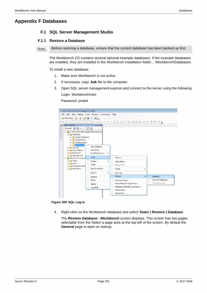
WorkBench User Manual Databases
Appendix F Databases
F.1 SQL Server Management Studio
F.1.1 Restore a Database
The Workbench CD contains several optional example databases. If the example databases are installed, they are installed in the Workbench installation folder... \Workbench\Databases
To install a new database:
1. Make sure Workbench is not active.
2. If necessary, copy .bak file to the computer.
3. Open SQL server management express and connect to the server using the following:
Login: WorkbenchUser
Password: probel
4. Right-click on the Workbench database and select Tasks | Restore | Database
The Restore Database - Workbench screen displays. This screen has two pages selectable from the Select a page area at the top-left of the screen. By default the General page is open on startup.
Note: Before restoring a database, ensure that the current database has been backed up first.
Figure 200 SQL Log-in
Issue1 Revision 5 Page 251 © 2017 SAM
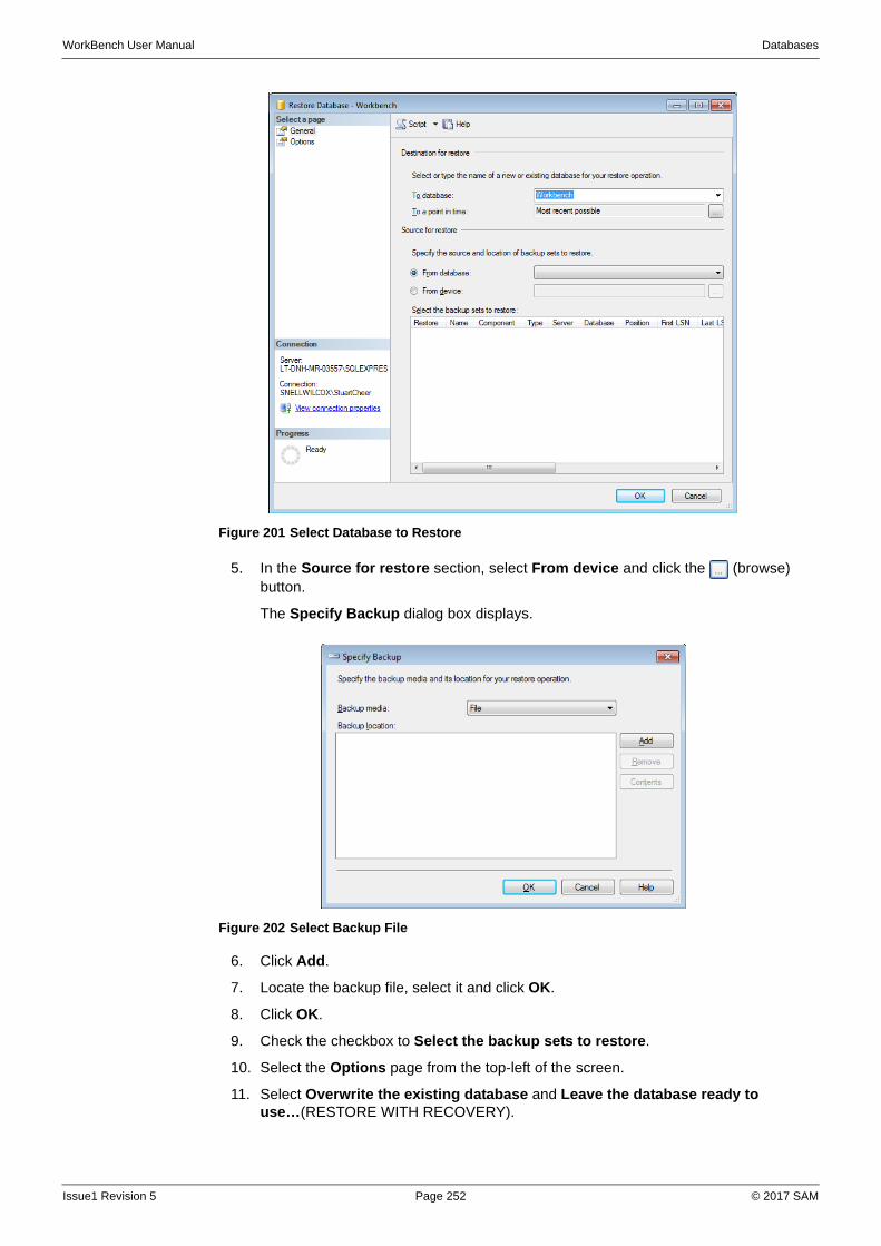
WorkBench User Manual Databases
5. In the Source for restore section, select From device and click the (browse) button.
The Specify Backup dialog box displays.
6. Click Add.
7. Locate the backup file, select it and click OK.
8. Click OK.
9. Check the checkbox to Select the backup sets to restore.
10. Select the Options page from the top-left of the screen.
11. Select Overwrite the existing database and Leave the database ready to use…(RESTORE WITH RECOVERY).
Figure 201 Select Database to Restore
Figure 202 Select Backup File
Issue1 Revision 5 Page 252 © 2017 SAM
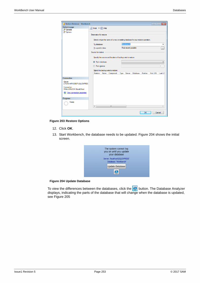
WorkBench User Manual Databases
12. Click OK.
13. Start Workbench, the database needs to be updated. Figure 204 shows the initial screen.
To view the differences between the databases, click the button. The Database Analyzer displays, indicating the parts of the database that will change when the database is updated, see Figure 205
Figure 203 Restore Options
Figure 204 Update Database
Issue1 Revision 5 Page 253 © 2017 SAM

WorkBench User Manual Databases
F.1.2 Backup a Database
A backup of the Workbench database should be kept.
To backup a database:
1. Make sure Workbench is not active.
2. Open SQL server management express and connect to the server.
3. Right click on the Workbench database and select Tasks | Back Up...
The Backup Database - Workbench screen displays, see Figure 206
4. Select a database backup destination.
5. Click OK.
Figure 205 Database Analyzer
Figure 206 Backup Database
Issue1 Revision 5 Page 254 © 2017 SAM
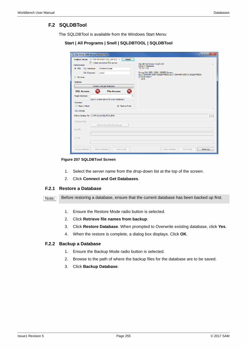
WorkBench User Manual Databases
F.2 SQLDBTool
The SQLDBTool is available from the Windows Start Menu:
Start | All Programs | Snell | SQLDBTOOL | SQLDBTool
1. Select the server name from the drop-down list at the top of the screen.
2. Click Connect and Get Databases.
F.2.1 Restore a Database
1. Ensure the Restore Mode radio button is selected.
2. Click Retrieve file names from backup.
3. Click Restore Database. When prompted to Overwrite existing database, click Yes.
4. When the restore is complete, a dialog box displays. Click OK.
F.2.2 Backup a Database
1. Ensure the Backup Mode radio button is selected.
2. Browse to the path of where the backup files for the database are to be saved.
3. Click Backup Database.
Figure 207 SQLDBTool Screen
Note: Before restoring a database, ensure that the current database has been backed up first.
Issue1 Revision 5 Page 255 © 2017 SAM
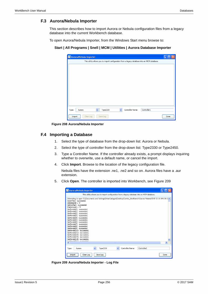
WorkBench User Manual Databases
F.3 Aurora/Nebula Importer
This section describes how to import Aurora or Nebula configuration files from a legacy database into the current Workbench database.
To open Aurora/Nebula Importer, from the Windows Start menu browse to:
Start | All Programs | Snell | MCM | Utilities | Aurora Database Importer
F.4 Importing a Database
1. Select the type of database from the drop-down list: Aurora or Nebula.
2. Select the type of controller from the drop-down list: Type2330 or Type2450.
3. Type a Controller Name. If the controller already exists, a prompt displays inquiring whether to overwrite, use a default name, or cancel the import.
4. Click Import. Browse to the location of the legacy configuration file.
Nebula files have the extension .ne1, .ne2 and so on. Aurora files have a .aur extension.
5. Click Open. The controller is imported into Workbench, see Figure 209
Figure 208 Aurora/Nebula Importer
Figure 209 Aurora/Nebula Importer - Log File
Issue1 Revision 5 Page 256 © 2017 SAM
WorkBench User Manual Databases
When the import is complete, the window lists all the items in the database that are imported.
6. To save the log, click Save Log.
The imported controllers are listed in Workbench Configuration mode.
F.5 Imported Data
The following data is imported:
• Matrices
• Levels
• Sources
• Source Associations (if enabled in the legacy database)
• Destination Associations
• Salvos
• Panel configuration
Defaulted Data
• Destinations
• Source Associations (if disabled in the legacy database)
• Inhibits
Issue1 Revision 5 Page 257 © 2017 SAM

WorkBench User Manual Databases
Issue1 Revision 5 Page 258 © 2017 SAM
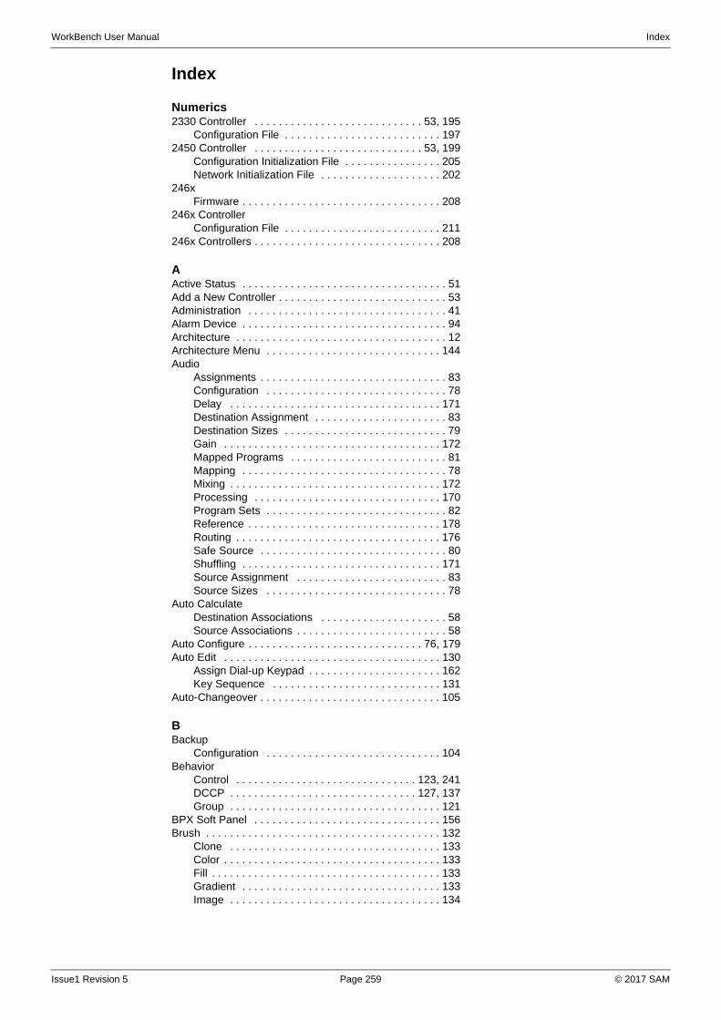
WorkBench User Manual Index
Index
Numerics2330 Controller . . . . . . . . . . . . . . . . . . . . . . . . . . . . 53, 195
Configuration File . . . . . . . . . . . . . . . . . . . . . . . . . . 1972450 Controller . . . . . . . . . . . . . . . . . . . . . . . . . . . . 53, 199
Configuration Initialization File . . . . . . . . . . . . . . . . 205Network Initialization File . . . . . . . . . . . . . . . . . . . . 202
246xFirmware . . . . . . . . . . . . . . . . . . . . . . . . . . . . . . . . . 208
246x ControllerConfiguration File . . . . . . . . . . . . . . . . . . . . . . . . . . 211
246x Controllers . . . . . . . . . . . . . . . . . . . . . . . . . . . . . . . 208
AActive Status . . . . . . . . . . . . . . . . . . . . . . . . . . . . . . . . . . 51Add a New Controller . . . . . . . . . . . . . . . . . . . . . . . . . . . . 53Administration . . . . . . . . . . . . . . . . . . . . . . . . . . . . . . . . . 41Alarm Device . . . . . . . . . . . . . . . . . . . . . . . . . . . . . . . . . . 94Architecture . . . . . . . . . . . . . . . . . . . . . . . . . . . . . . . . . . . 12Architecture Menu . . . . . . . . . . . . . . . . . . . . . . . . . . . . . 144Audio
Assignments . . . . . . . . . . . . . . . . . . . . . . . . . . . . . . . 83Configuration . . . . . . . . . . . . . . . . . . . . . . . . . . . . . . 78Delay . . . . . . . . . . . . . . . . . . . . . . . . . . . . . . . . . . . 171Destination Assignment . . . . . . . . . . . . . . . . . . . . . . 83Destination Sizes . . . . . . . . . . . . . . . . . . . . . . . . . . . 79Gain . . . . . . . . . . . . . . . . . . . . . . . . . . . . . . . . . . . . 172Mapped Programs . . . . . . . . . . . . . . . . . . . . . . . . . . 81Mapping . . . . . . . . . . . . . . . . . . . . . . . . . . . . . . . . . . 78Mixing . . . . . . . . . . . . . . . . . . . . . . . . . . . . . . . . . . . 172Processing . . . . . . . . . . . . . . . . . . . . . . . . . . . . . . . 170Program Sets . . . . . . . . . . . . . . . . . . . . . . . . . . . . . . 82Reference . . . . . . . . . . . . . . . . . . . . . . . . . . . . . . . . 178Routing . . . . . . . . . . . . . . . . . . . . . . . . . . . . . . . . . . 176Safe Source . . . . . . . . . . . . . . . . . . . . . . . . . . . . . . . 80Shuffling . . . . . . . . . . . . . . . . . . . . . . . . . . . . . . . . . 171Source Assignment . . . . . . . . . . . . . . . . . . . . . . . . . 83Source Sizes . . . . . . . . . . . . . . . . . . . . . . . . . . . . . . 78
Auto CalculateDestination Associations . . . . . . . . . . . . . . . . . . . . . 58Source Associations . . . . . . . . . . . . . . . . . . . . . . . . . 58
Auto Configure . . . . . . . . . . . . . . . . . . . . . . . . . . . . . 76, 179Auto Edit . . . . . . . . . . . . . . . . . . . . . . . . . . . . . . . . . . . . 130
Assign Dial-up Keypad . . . . . . . . . . . . . . . . . . . . . . 162Key Sequence . . . . . . . . . . . . . . . . . . . . . . . . . . . . 131
Auto-Changeover . . . . . . . . . . . . . . . . . . . . . . . . . . . . . . 105
BBackup
Configuration . . . . . . . . . . . . . . . . . . . . . . . . . . . . . 104Behavior
Control . . . . . . . . . . . . . . . . . . . . . . . . . . . . . . 123, 241DCCP . . . . . . . . . . . . . . . . . . . . . . . . . . . . . . . 127, 137Group . . . . . . . . . . . . . . . . . . . . . . . . . . . . . . . . . . . 121
BPX Soft Panel . . . . . . . . . . . . . . . . . . . . . . . . . . . . . . . 156Brush . . . . . . . . . . . . . . . . . . . . . . . . . . . . . . . . . . . . . . . 132
Clone . . . . . . . . . . . . . . . . . . . . . . . . . . . . . . . . . . . 133Color . . . . . . . . . . . . . . . . . . . . . . . . . . . . . . . . . . . . 133Fill . . . . . . . . . . . . . . . . . . . . . . . . . . . . . . . . . . . . . . 133Gradient . . . . . . . . . . . . . . . . . . . . . . . . . . . . . . . . . 133Image . . . . . . . . . . . . . . . . . . . . . . . . . . . . . . . . . . . 134
Issue1 Revision 5 Page 259 © 2017 SAM
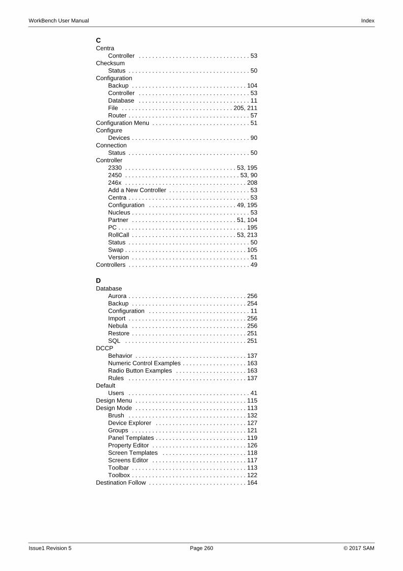
WorkBench User Manual Index
CCentra
Controller . . . . . . . . . . . . . . . . . . . . . . . . . . . . . . . . . 53Checksum
Status . . . . . . . . . . . . . . . . . . . . . . . . . . . . . . . . . . . . 50Configuration
Backup . . . . . . . . . . . . . . . . . . . . . . . . . . . . . . . . . . 104Controller . . . . . . . . . . . . . . . . . . . . . . . . . . . . . . . . . 53Database . . . . . . . . . . . . . . . . . . . . . . . . . . . . . . . . . 11File . . . . . . . . . . . . . . . . . . . . . . . . . . . . . . . . . 205, 211Router . . . . . . . . . . . . . . . . . . . . . . . . . . . . . . . . . . . . 57
Configuration Menu . . . . . . . . . . . . . . . . . . . . . . . . . . . . . 51Configure
Devices . . . . . . . . . . . . . . . . . . . . . . . . . . . . . . . . . . . 90Connection
Status . . . . . . . . . . . . . . . . . . . . . . . . . . . . . . . . . . . . 50Controller
2330 . . . . . . . . . . . . . . . . . . . . . . . . . . . . . . . . . 53, 1952450 . . . . . . . . . . . . . . . . . . . . . . . . . . . . . . . . . . 53, 90246x . . . . . . . . . . . . . . . . . . . . . . . . . . . . . . . . . . . . 208Add a New Controller . . . . . . . . . . . . . . . . . . . . . . . . 53Centra . . . . . . . . . . . . . . . . . . . . . . . . . . . . . . . . . . . . 53Configuration . . . . . . . . . . . . . . . . . . . . . . . . . . 49, 195Nucleus . . . . . . . . . . . . . . . . . . . . . . . . . . . . . . . . . . . 53Partner . . . . . . . . . . . . . . . . . . . . . . . . . . . . . . . 51, 104PC . . . . . . . . . . . . . . . . . . . . . . . . . . . . . . . . . . . . . . 195RollCall . . . . . . . . . . . . . . . . . . . . . . . . . . . . . . . 53, 213Status . . . . . . . . . . . . . . . . . . . . . . . . . . . . . . . . . . . . 50Swap . . . . . . . . . . . . . . . . . . . . . . . . . . . . . . . . . . . . 105Version . . . . . . . . . . . . . . . . . . . . . . . . . . . . . . . . . . . 51
Controllers . . . . . . . . . . . . . . . . . . . . . . . . . . . . . . . . . . . . 49
DDatabase
Aurora . . . . . . . . . . . . . . . . . . . . . . . . . . . . . . . . . . . 256Backup . . . . . . . . . . . . . . . . . . . . . . . . . . . . . . . . . . 254Configuration . . . . . . . . . . . . . . . . . . . . . . . . . . . . . . 11Import . . . . . . . . . . . . . . . . . . . . . . . . . . . . . . . . . . . 256Nebula . . . . . . . . . . . . . . . . . . . . . . . . . . . . . . . . . . 256Restore . . . . . . . . . . . . . . . . . . . . . . . . . . . . . . . . . . 251SQL . . . . . . . . . . . . . . . . . . . . . . . . . . . . . . . . . . . . 251
DCCPBehavior . . . . . . . . . . . . . . . . . . . . . . . . . . . . . . . . . 137Numeric Control Examples . . . . . . . . . . . . . . . . . . . 163Radio Button Examples . . . . . . . . . . . . . . . . . . . . . 163Rules . . . . . . . . . . . . . . . . . . . . . . . . . . . . . . . . . . . 137
DefaultUsers . . . . . . . . . . . . . . . . . . . . . . . . . . . . . . . . . . . . 41
Design Menu . . . . . . . . . . . . . . . . . . . . . . . . . . . . . . . . . 115Design Mode . . . . . . . . . . . . . . . . . . . . . . . . . . . . . . . . . 113
Brush . . . . . . . . . . . . . . . . . . . . . . . . . . . . . . . . . . . 132Device Explorer . . . . . . . . . . . . . . . . . . . . . . . . . . . 127Groups . . . . . . . . . . . . . . . . . . . . . . . . . . . . . . . . . . 121Panel Templates . . . . . . . . . . . . . . . . . . . . . . . . . . . 119Property Editor . . . . . . . . . . . . . . . . . . . . . . . . . . . . 126Screen Templates . . . . . . . . . . . . . . . . . . . . . . . . . 118Screens Editor . . . . . . . . . . . . . . . . . . . . . . . . . . . . 117Toolbar . . . . . . . . . . . . . . . . . . . . . . . . . . . . . . . . . . 113Toolbox . . . . . . . . . . . . . . . . . . . . . . . . . . . . . . . . . . 122
Destination Follow . . . . . . . . . . . . . . . . . . . . . . . . . . . . . 164
Issue1 Revision 5 Page 260 © 2017 SAM
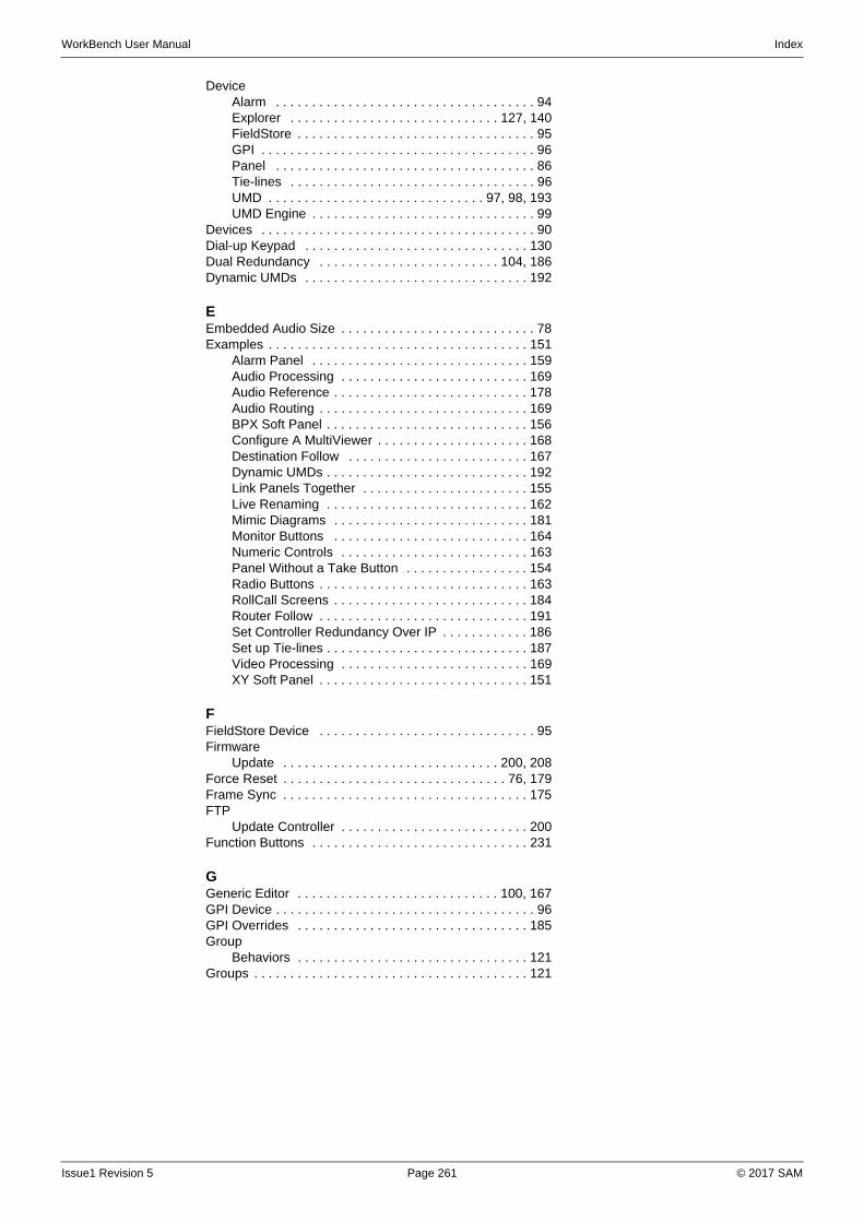
WorkBench User Manual Index
DeviceAlarm . . . . . . . . . . . . . . . . . . . . . . . . . . . . . . . . . . . . 94Explorer . . . . . . . . . . . . . . . . . . . . . . . . . . . . . 127, 140FieldStore . . . . . . . . . . . . . . . . . . . . . . . . . . . . . . . . . 95GPI . . . . . . . . . . . . . . . . . . . . . . . . . . . . . . . . . . . . . . 96Panel . . . . . . . . . . . . . . . . . . . . . . . . . . . . . . . . . . . . 86Tie-lines . . . . . . . . . . . . . . . . . . . . . . . . . . . . . . . . . . 96UMD . . . . . . . . . . . . . . . . . . . . . . . . . . . . . . 97, 98, 193UMD Engine . . . . . . . . . . . . . . . . . . . . . . . . . . . . . . . 99
Devices . . . . . . . . . . . . . . . . . . . . . . . . . . . . . . . . . . . . . . 90Dial-up Keypad . . . . . . . . . . . . . . . . . . . . . . . . . . . . . . . 130Dual Redundancy . . . . . . . . . . . . . . . . . . . . . . . . . 104, 186Dynamic UMDs . . . . . . . . . . . . . . . . . . . . . . . . . . . . . . . 192
EEmbedded Audio Size . . . . . . . . . . . . . . . . . . . . . . . . . . . 78Examples . . . . . . . . . . . . . . . . . . . . . . . . . . . . . . . . . . . . 151
Alarm Panel . . . . . . . . . . . . . . . . . . . . . . . . . . . . . . 159Audio Processing . . . . . . . . . . . . . . . . . . . . . . . . . . 169Audio Reference . . . . . . . . . . . . . . . . . . . . . . . . . . . 178Audio Routing . . . . . . . . . . . . . . . . . . . . . . . . . . . . . 169BPX Soft Panel . . . . . . . . . . . . . . . . . . . . . . . . . . . . 156Configure A MultiViewer . . . . . . . . . . . . . . . . . . . . . 168Destination Follow . . . . . . . . . . . . . . . . . . . . . . . . . 167Dynamic UMDs . . . . . . . . . . . . . . . . . . . . . . . . . . . . 192Link Panels Together . . . . . . . . . . . . . . . . . . . . . . . 155Live Renaming . . . . . . . . . . . . . . . . . . . . . . . . . . . . 162Mimic Diagrams . . . . . . . . . . . . . . . . . . . . . . . . . . . 181Monitor Buttons . . . . . . . . . . . . . . . . . . . . . . . . . . . 164Numeric Controls . . . . . . . . . . . . . . . . . . . . . . . . . . 163Panel Without a Take Button . . . . . . . . . . . . . . . . . 154Radio Buttons . . . . . . . . . . . . . . . . . . . . . . . . . . . . . 163RollCall Screens . . . . . . . . . . . . . . . . . . . . . . . . . . . 184Router Follow . . . . . . . . . . . . . . . . . . . . . . . . . . . . . 191Set Controller Redundancy Over IP . . . . . . . . . . . . 186Set up Tie-lines . . . . . . . . . . . . . . . . . . . . . . . . . . . . 187Video Processing . . . . . . . . . . . . . . . . . . . . . . . . . . 169XY Soft Panel . . . . . . . . . . . . . . . . . . . . . . . . . . . . . 151
FFieldStore Device . . . . . . . . . . . . . . . . . . . . . . . . . . . . . . 95Firmware
Update . . . . . . . . . . . . . . . . . . . . . . . . . . . . . . 200, 208Force Reset . . . . . . . . . . . . . . . . . . . . . . . . . . . . . . . 76, 179Frame Sync . . . . . . . . . . . . . . . . . . . . . . . . . . . . . . . . . . 175FTP
Update Controller . . . . . . . . . . . . . . . . . . . . . . . . . . 200Function Buttons . . . . . . . . . . . . . . . . . . . . . . . . . . . . . . 231
GGeneric Editor . . . . . . . . . . . . . . . . . . . . . . . . . . . . 100, 167GPI Device . . . . . . . . . . . . . . . . . . . . . . . . . . . . . . . . . . . . 96GPI Overrides . . . . . . . . . . . . . . . . . . . . . . . . . . . . . . . . 185Group
Behaviors . . . . . . . . . . . . . . . . . . . . . . . . . . . . . . . . 121Groups . . . . . . . . . . . . . . . . . . . . . . . . . . . . . . . . . . . . . . 121
Issue1 Revision 5 Page 261 © 2017 SAM
WorkBench User Manual Index
HHardware Panels . . . . . . . . . . . . . . . . . . . . . . . . . . 119, 229
Configuration Editor . . . . . . . . . . . . . . . . . . . . . . . . . 88Function Buttons . . . . . . . . . . . . . . . . . . . . . . . . . . . 231Key Sequences . . . . . . . . . . . . . . . . . . . . . . . . . . . 128Panel Features . . . . . . . . . . . . . . . . . . . . . . . . . . . . 231Panel Switch Settings . . . . . . . . . . . . . . . . . . . . . . . 231Ports . . . . . . . . . . . . . . . . . . . . . . . . . . . . . . . . . . . . . 89Special Functions . . . . . . . . . . . . . . . . . . . . . . . . . . 231Supported Panels . . . . . . . . . . . . . . . . . . . . . . . . . . 229Wizard . . . . . . . . . . . . . . . . . . . . . . . . . . . . . . . . . . . 87
Home Screen . . . . . . . . . . . . . . . . . . . . . . . . . . . . . . . . . . 37
IImage
Brush . . . . . . . . . . . . . . . . . . . . . . . . . . . . . . . . . . . 134Installation . . . . . . . . . . . . . . . . . . . . . . . . . . . . . . . . . . . . 17
Requirements . . . . . . . . . . . . . . . . . . . . . . . . . . . . . . 17IP Port Configuration . . . . . . . . . . . . . . . . . . . . . . . . . . . . 62
KKey Assignment . . . . . . . . . . . . . . . . . . . . . . . . . . . . . . . 131Key Sequence . . . . . . . . . . . . . . . . . . . . . . . . . . . . . . . . 128Key Sequence Generation . . . . . . . . . . . . . . . . . . . . . . . 131Keypad
Dial-up . . . . . . . . . . . . . . . . . . . . . . . . . . . . . . . . . . 130
LLevels
Configuration Editor . . . . . . . . . . . . . . . . . . . . . . . . . 67Router Configuration . . . . . . . . . . . . . . . . . . . . . . . . 58
Link Panels . . . . . . . . . . . . . . . . . . . . . . . . . . . . . . 155, 158Loading a Snapshot . . . . . . . . . . . . . . . . . . . . . . . . . . . . 109Log . . . . . . . . . . . . . . . . . . . . . . . . . . . . . . . . . . . . . . . . . . 39Logging Configuration . . . . . . . . . . . . . . . . . . . . . . . . . . 179Logical Destinations . . . . . . . . . . . . . . . . . . . . . . . . . . 76, 85
MMatrices
Router Configuration . . . . . . . . . . . . . . . . . . . . . . . . 58Matrix
Ports . . . . . . . . . . . . . . . . . . . . . . . . . . . . . . . . . . . . . 63Membership . . . . . . . . . . . . . . . . . . . . . . . . . . . . . . . . . . . 44Menu
Architecture . . . . . . . . . . . . . . . . . . . . . . . . . . . . . . 144Configuration . . . . . . . . . . . . . . . . . . . . . . . . . . . . . . 51Design . . . . . . . . . . . . . . . . . . . . . . . . . . . . . . . . . . 115
Mimic Diagrams . . . . . . . . . . . . . . . . . . . . . . . . . . . 148, 181Mixing . . . . . . . . . . . . . . . . . . . . . . . . . . . . . . . . . . . . . . 172Module
IDs . . . . . . . . . . . . . . . . . . . . . . . . . . . . . . . . . . . 75, 84Module Locations
Cygnus . . . . . . . . . . . . . . . . . . . . . . . . . . . . . . . . . . 227Pyxis . . . . . . . . . . . . . . . . . . . . . . . . . . . . . . . . . . . . 219Sirius . . . . . . . . . . . . . . . . . . . . . . . . . . . . . . . . 221, 223
MultiViewer . . . . . . . . . . . . . . . . . . . . . . . . . . . . . . . . . . 168
NNetworks . . . . . . . . . . . . . . . . . . . . . . . . . . . . . . . . . . . . . 49
Issue1 Revision 5 Page 262 © 2017 SAM
WorkBench User Manual Index
NucleusAuto Configure . . . . . . . . . . . . . . . . . . . . . . . . . 76, 179Controller . . . . . . . . . . . . . . . . . . . . . . . . . . . . . . . . . 53Features . . . . . . . . . . . . . . . . . . . . . . . . . . . . . 199, 208Firmware . . . . . . . . . . . . . . . . . . . . . . . . . . . . . . . . . 200Force Reset . . . . . . . . . . . . . . . . . . . . . . . . . . . 76, 179Logging Configuration . . . . . . . . . . . . . . . . . . 179, 200Logical Destinations . . . . . . . . . . . . . . . . . . . . . . 76, 85Logical Sources . . . . . . . . . . . . . . . . . . . . . . . . . 76, 85Module IDs . . . . . . . . . . . . . . . . . . . . . . . . . . . . . 75, 84
OOID Rewrite Helper . . . . . . . . . . . . . . . . . . . . . . . . . . . . 106Online Editor . . . . . . . . . . . . . . . . . . . . . . . . . . . . . . . . . 101
PPanel
Device . . . . . . . . . . . . . . . . . . . . . . . . . . . . . . . . . . . . 86Hardware . . . . . . . . . . . . . . . . . . . . . . . . . . . . 119, 231Soft . . . . . . . . . . . . . . . . . . . . . . . . . . . . . . . . . . . . . 119Templates . . . . . . . . . . . . . . . . . . . . . . . . . . . . . . . . 119
Panels . . . . . . . . . . . . . . . . . . . . . . . . . . . . . . . . . . . . . . 119Partner . . . . . . . . . . . . . . . . . . . . . . . . . . . . . . . . . . . 51, 104Password . . . . . . . . . . . . . . . . . . . . . . . . . . . . . . . . . . . . . 33Pbak Deploy
Nucleus Update . . . . . . . . . . . . . . . . . . . . . . . . . . . 200Software Tool . . . . . . . . . . . . . . . . . . . . . . . . . . . . . . 35
PC Controller . . . . . . . . . . . . . . . . . . . . . . . . . . . . . . . . . 195Permissions
Screens . . . . . . . . . . . . . . . . . . . . . . . . . . . . . . . 45, 46Port Configuration
IP . . . . . . . . . . . . . . . . . . . . . . . . . . . . . . . . . . . . . . . 63Serial . . . . . . . . . . . . . . . . . . . . . . . . . . . . . . . . . . . . 61
Property Editor . . . . . . . . . . . . . . . . . . . . . . . . . . . . . . . . 126Property Window . . . . . . . . . . . . . . . . . . . . . . . . . . . . . . 126Push and Pull Configuration . . . . . . . . . . . . . . . . . . . . . 103Push Failure . . . . . . . . . . . . . . . . . . . . . . . . . . . . . . . . . . 103Pyxis
Module Locations . . . . . . . . . . . . . . . . . . . . . . . . . . 219Routers . . . . . . . . . . . . . . . . . . . . . . . . . . . . . . . . . . 215Sample Database . . . . . . . . . . . . . . . . . . . . . . . . . . 215
RRadio Buttons Example . . . . . . . . . . . . . . . . . . . . . . . . . 163Redundancy . . . . . . . . . . . . . . . . . . . . . . . . . . . . . . . . . . 104Reference
Audio . . . . . . . . . . . . . . . . . . . . . . . . . . . . . . . . . . . 178Video . . . . . . . . . . . . . . . . . . . . . . . . . . . . . . . . 68, 178
Reset . . . . . . . . . . . . . . . . . . . . . . . . . . . . . . . . . . . . . . . 104Restore
Database . . . . . . . . . . . . . . . . . . . . . . . . . . . . . . . . 251Roles . . . . . . . . . . . . . . . . . . . . . . . . . . . . . . . . . . . . . . . . 43
Adding . . . . . . . . . . . . . . . . . . . . . . . . . . . . . . . . . . . 43Default . . . . . . . . . . . . . . . . . . . . . . . . . . . . . . . . . . . 43Membership . . . . . . . . . . . . . . . . . . . . . . . . . . . . . . . 44
RollCallController . . . . . . . . . . . . . . . . . . . . . . . . . . . . . 53, 213Generic Editor . . . . . . . . . . . . . . . . . . . . . . . . . . . . . . 56Screens . . . . . . . . . . . . . . . . . . . . . . . . . . . . . . . . . 184
RouterConfiguration . . . . . . . . . . . . . . . . . . . . . . . . . . . . . . 57Hardware Config . . . . . . . . . . . . . . . . . . . . . . . . . . . . 73
Routing . . . . . . . . . . . . . . . . . . . . . . . . . . . . . . . . . . . . . 176Audio . . . . . . . . . . . . . . . . . . . . . . . . . . . . . . . . . . . 176Video . . . . . . . . . . . . . . . . . . . . . . . . . . . . . . . . . . . 177
Issue1 Revision 5 Page 263 © 2017 SAM
WorkBench User Manual Index
Rules . . . . . . . . . . . . . . . . . . . . . . . . . . . . . . . . . . . . . . . 135Service . . . . . . . . . . . . . . . . . . . . . . . . . . . . . . . . . . 142Status . . . . . . . . . . . . . . . . . . . . . . . . . . . . . . . . . . . 142Toolbar . . . . . . . . . . . . . . . . . . . . . . . . . . . . . . . . . . 136Toolbox . . . . . . . . . . . . . . . . . . . . . . . . . . . . . . . . . . 136
Rules Menu . . . . . . . . . . . . . . . . . . . . . . . . . . . . . . . . . . 135
SSafe Source . . . . . . . . . . . . . . . . . . . . . . . . . . . . . . . . . . . 80Salvos
Configuration . . . . . . . . . . . . . . . . . . . . . . . . . . . . . . 58Sample Panels
Pyxis . . . . . . . . . . . . . . . . . . . . . . . . . . . . . . . . . . . . 218Sample Rate Conversion . . . . . . . . . . . . . . . . . . . . . . . . 173Screen
Design Mode . . . . . . . . . . . . . . . . . . . . . . . . . . . . . 115Templates . . . . . . . . . . . . . . . . . . . . . . . . . . . . . . . . 118
ScreensPermissions . . . . . . . . . . . . . . . . . . . . . . . . . . . . . . . 45
Sequence Sets . . . . . . . . . . . . . . . . . . . . . . . . . . . . . . . . 89Serial Port Configuration . . . . . . . . . . . . . . . . . . . . . . . . . 61Shuffling . . . . . . . . . . . . . . . . . . . . . . . . . . . . . . . . . . . . . 171Sirius
Module Locations . . . . . . . . . . . . . . . . . . . . . . . . . . 223Snapshot
Editor . . . . . . . . . . . . . . . . . . . . . . . . . . . . . . . . . . . 107Load . . . . . . . . . . . . . . . . . . . . . . . . . . . . . . . . . . . . 109Save . . . . . . . . . . . . . . . . . . . . . . . . . . . . . . . . . . . . 108
Soft Panels . . . . . . . . . . . . . . . . . . . . . . . . . . . . . . 115, 119BPX . . . . . . . . . . . . . . . . . . . . . . . . . . . . . . . . . . . . 156Mimic . . . . . . . . . . . . . . . . . . . . . . . . . . . . . . . . . . . 183XY . . . . . . . . . . . . . . . . . . . . . . . . . . . . . . . . . . . . . . 151
Special Function Keys . . . . . . . . . . . . . . . . . . . . . . . . . . 231SQL Databases . . . . . . . . . . . . . . . . . . . . . . . . . . . . . . . 251Status
Activity . . . . . . . . . . . . . . . . . . . . . . . . . . . . . . . . . . . 51Checksum . . . . . . . . . . . . . . . . . . . . . . . . . . . . . . . . . 50Connection . . . . . . . . . . . . . . . . . . . . . . . . . . . . . . . . 50Controller . . . . . . . . . . . . . . . . . . . . . . . . . . . . . . . . . 50Partner . . . . . . . . . . . . . . . . . . . . . . . . . . . . . . . . . . . 51
Stereo Mode . . . . . . . . . . . . . . . . . . . . . . . . . . . . . . . . . 173Swap Controllers . . . . . . . . . . . . . . . . . . . . . . . . . . . . . . 105System Architecture . . . . . . . . . . . . . . . . . . . . . . . . . . . . 143
Devices Types . . . . . . . . . . . . . . . . . . . . . . . . . . . . 144Toolbar . . . . . . . . . . . . . . . . . . . . . . . . . . . . . . . . . . 143
TTag Names . . . . . . . . . . . . . . . . . . . . . . . . . . . . . . . . . . . 60Take Button . . . . . . . . . . . . . . . . . . . . . . . . . . . . . . . . . . 153Tie-lines . . . . . . . . . . . . . . . . . . . . . . . . . . . . . . . . . . . . . 187Tie-Lines Device . . . . . . . . . . . . . . . . . . . . . . . . . . . . . . . 96Toolbar
Architecture . . . . . . . . . . . . . . . . . . . . . . . . . . . . . . 143Design Mode . . . . . . . . . . . . . . . . . . . . . . . . . . . . . 113Rules . . . . . . . . . . . . . . . . . . . . . . . . . . . . . . . . . . . 136
ToolboxDesign Mode . . . . . . . . . . . . . . . . . . . . . . . . . . . . . 122Rules . . . . . . . . . . . . . . . . . . . . . . . . . . . . . . . . . . . 136
UUMD Device . . . . . . . . . . . . . . . . . . . . . . . . . . . . . . . . . . . 98UMD Engine Device . . . . . . . . . . . . . . . . . . . . . . . . . . . . 99UMDs . . . . . . . . . . . . . . . . . . . . . . . . . . . . . . . . 97, 192, 193
Issue1 Revision 5 Page 264 © 2017 SAM
WorkBench User Manual Index
UsersAdding . . . . . . . . . . . . . . . . . . . . . . . . . . . . . . . . . . . 42Default . . . . . . . . . . . . . . . . . . . . . . . . . . . . . . . . . . . 41Roles . . . . . . . . . . . . . . . . . . . . . . . . . . . . . . . . . . . . 43
VVersion
Controller . . . . . . . . . . . . . . . . . . . . . . . . . . . . . . . . . 51
WWindow
Docking . . . . . . . . . . . . . . . . . . . . . . . . . . . . . . . . . . . 38Wizards
Auto Configure . . . . . . . . . . . . . . . . . . . . . . . . . 76, 179Hardware Panels . . . . . . . . . . . . . . . . . . . . . . . . . . . 87
Workbench . . . . . . . . . . . . . . . . . . . . . . . . . . . . . . . . . . . . 11Worked Examples
See ’Examples’ . . . . . . . . . . . . . . . . . . . . . . . . . . . . 151
Issue1 Revision 5 Page 265 © 2017 SAM

WorkBench User Manual Index
Issue1 Revision 5 Page 266 © 2017 SAM
Related Documents


![CONSIDERATIONS REGARDING THE NORMAL STRESS (X ......[1] Ansys Workbench User Manual [2] Huei – Huang Lee, Finite Element Simulations with Ansys Workbench 12, Schroff Development](https://static.cupdf.com/doc/110x72/606684f26a301352a77e84e2/considerations-regarding-the-normal-stress-x-1-ansys-workbench-user-manual.jpg)