© Parker Hannifin Corporation, 2002 Agilent Membrane Nitrogen Generator Service Guide © Parker Hannifin Corporation, 2002

Welcome message from author
This document is posted to help you gain knowledge. Please leave a comment to let me know what you think about it! Share it to your friends and learn new things together.
Transcript
© Parker Hannifin Corporation, 2002
Agilent Membrane Nitrogen Generator
Service Guide
© Parker Hannifin Corporation, 2002
© Parker Hannifin Corporation, 2002
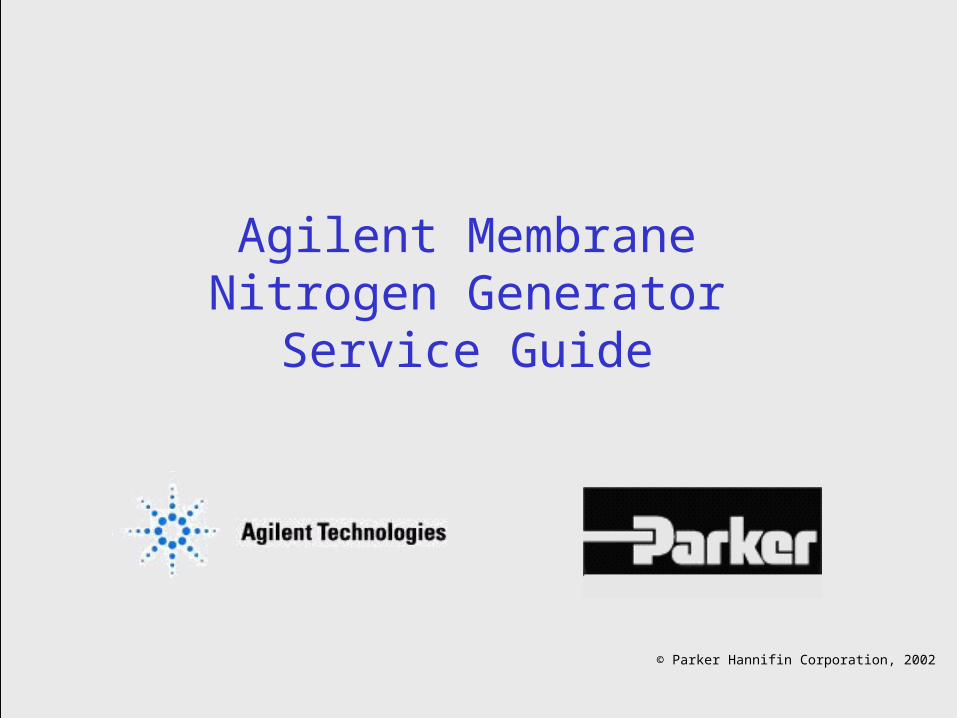
Agilent Membrane Nitrogen Generator Service Guide
Technology Overview
Troubleshooting Guide
Routine Maintenance Guide
Membrane Replacement Guide
Nitrogen Generator Manuals
Global Technical Service Contacts
How to use this guide
Click buttons to forward to section
© Parker Hannifin Corporation, 2002
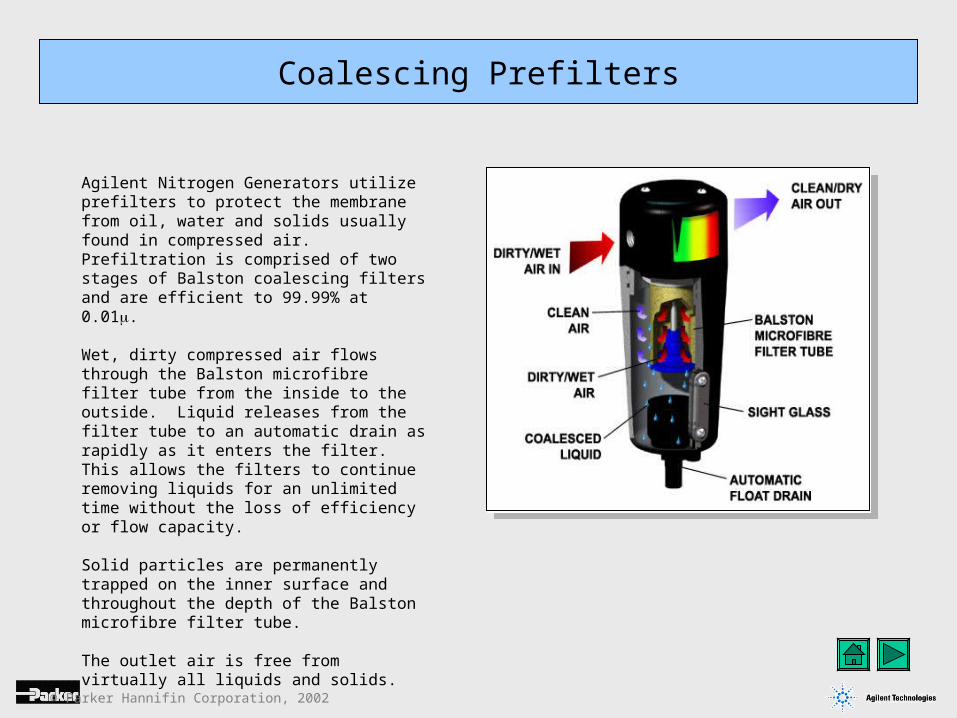
Agilent Nitrogen Generators utilize prefilters to protect the membrane from oil, water and solids usually found in compressed air. Prefiltration is comprised of two stages of Balston coalescing filters and are efficient to 99.99% at 0.01.
Wet, dirty compressed air flows through the Balston microfibre filter tube from the inside to the outside. Liquid releases from the filter tube to an automatic drain as rapidly as it enters the filter. This allows the filters to continue removing liquids for an unlimited time without the loss of efficiency or flow capacity.
Solid particles are permanently trapped on the inner surface and throughout the depth of the Balston microfibre filter tube.
The outlet air is free from virtually all liquids and solids.
Coalescing Prefilters
© Parker Hannifin Corporation, 2002
Selective Permeation Membrane
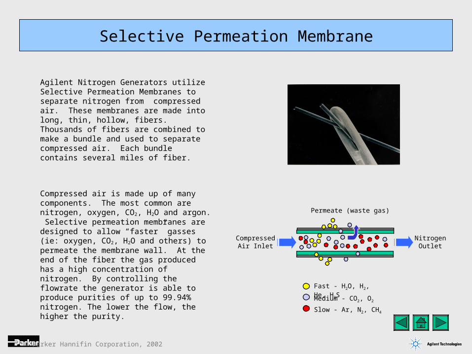
CompressedAir Inlet
Medium - CO2, O2
Fast - H2O, H2, He, H2S
Slow - Ar, N2, CH4
Agilent Nitrogen Generators utilize Selective Permeation Membranes to separate nitrogen from compressed air. These membranes are made into long, thin, hollow, fibers. Thousands of fibers are combined to make a bundle and used to separate compressed air. Each bundle contains several miles of fiber.
Permeate (waste gas)
NitrogenOutlet
Compressed air is made up of many components. The most common are nitrogen, oxygen, CO2, H2O and argon. Selective permeation membranes are designed to allow “faster” gasses (ie: oxygen, CO2, H2O and others) to permeate the membrane wall. At the end of the fiber the gas produced has a high concentration of nitrogen. By controlling the flowrate the generator is able to produce purities of up to 99.94% nitrogen. The lower the flow, the higher the purity.
© Parker Hannifin Corporation, 2002
Carbon Filter
Engineered Systems
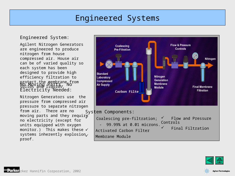
Engineered System:
Agilent Nitrogen Generators are engineered to produce nitrogen from house compressed air. House air can be of varied quality so each system has been designed to provide high efficiency filtration to protect the membrane from solids and liquids.
No Moving Parts, No Electricity Needed:
Nitrogen Generators use the pressure from compressed air pressure to separate nitrogen from air. There are no moving parts and they require no electricity (except for units equipped with oxygen monitor.) This makes these systems inherently explosion proof.
System Components: Coalescing pre-filtration;
- 99.99% at 0.01 microns. Activated Carbon Filter Membrane Module
Flow and Pressure Controls Final Filtration
© Parker Hannifin Corporation, 2002
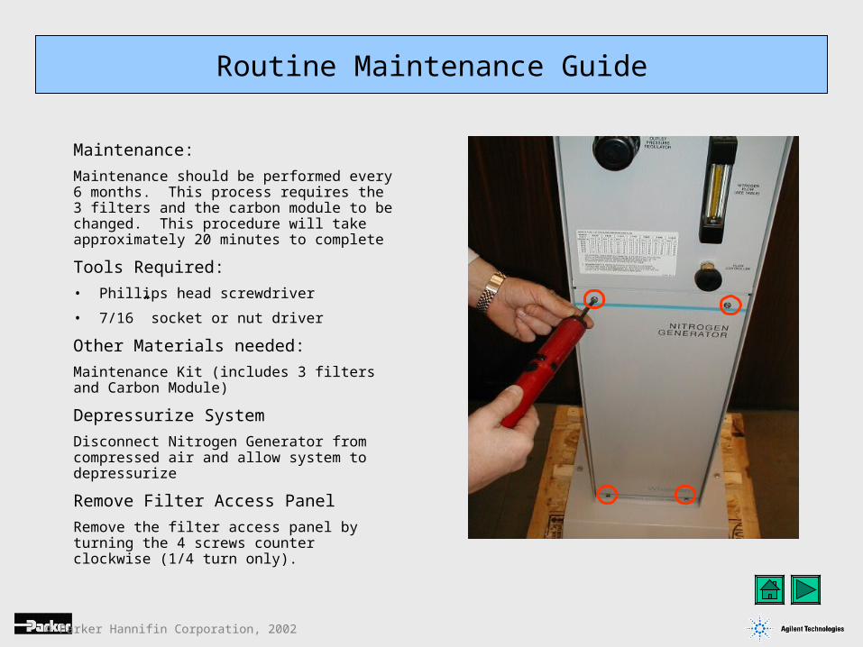
Maintenance:
Maintenance should be performed every 6 months. This process requires the 3 filters and the carbon module to be changed. This procedure will take approximately 20 minutes to complete
Tools Required:
• Phillips head screwdriver
• 7/16” socket or nut driver
Other Materials needed:
Maintenance Kit (includes 3 filters and Carbon Module)
Depressurize System
Disconnect Nitrogen Generator from compressed air and allow system to depressurize
Remove Filter Access Panel
Remove the filter access panel by turning the 4 screws counter clockwise (1/4 turn only).
Routine Maintenance Guide
© Parker Hannifin Corporation, 2002
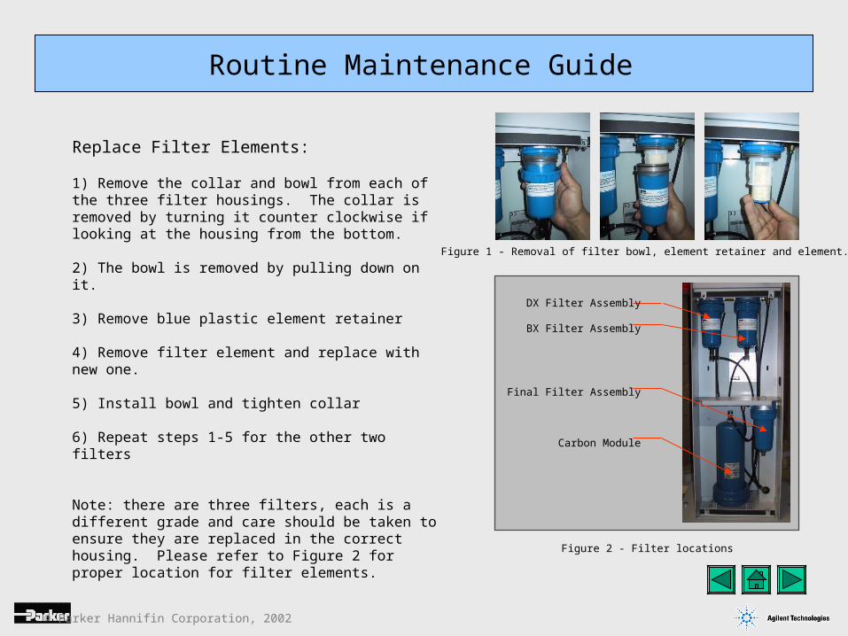
Replace Filter Elements:
1) Remove the collar and bowl from each of the three filter housings. The collar is removed by turning it counter clockwise if looking at the housing from the bottom.
2) The bowl is removed by pulling down on it.
3) Remove blue plastic element retainer
4) Remove filter element and replace with new one.
5) Install bowl and tighten collar
6) Repeat steps 1-5 for the other two filters
Note: there are three filters, each is a different grade and care should be taken to ensure they are replaced in the correct housing. Please refer to Figure 2 for proper location for filter elements.
Routine Maintenance Guide
DX Filter Assembly
BX Filter Assembly
Final Filter Assembly
Carbon Module
Figure 2 - Filter locations
Figure 1 - Removal of filter bowl, element retainer and element.
© Parker Hannifin Corporation, 2002
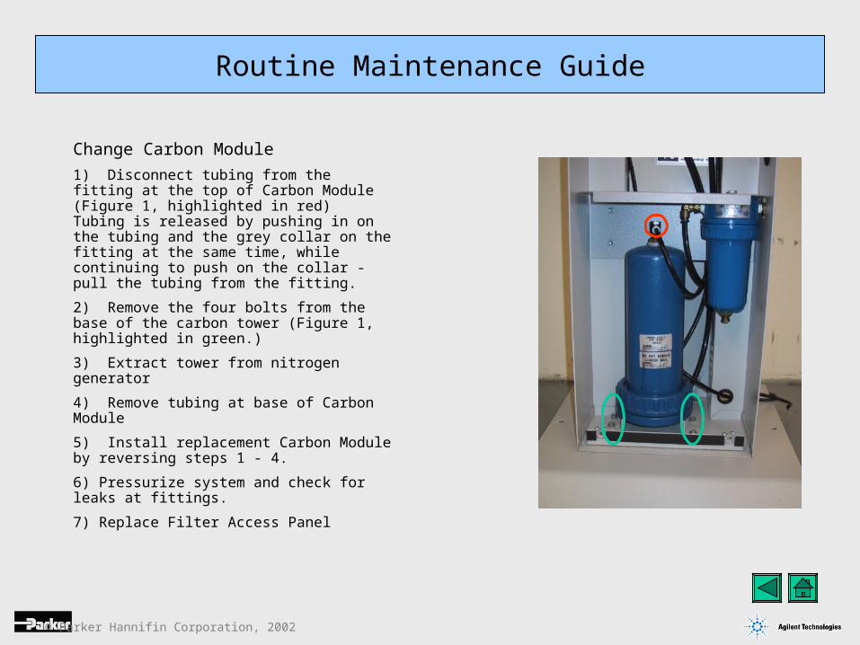
Change Carbon Module
1) Disconnect tubing from the fitting at the top of Carbon Module (Figure 1, highlighted in red) Tubing is released by pushing in on the tubing and the grey collar on the fitting at the same time, while continuing to push on the collar - pull the tubing from the fitting.
2) Remove the four bolts from the base of the carbon tower (Figure 1, highlighted in green.)
3) Extract tower from nitrogen generator
4) Remove tubing at base of Carbon Module
5) Install replacement Carbon Module by reversing steps 1 - 4.
6) Pressurize system and check for leaks at fittings.
7) Replace Filter Access Panel
Routine Maintenance Guide

© Parker Hannifin Corporation, 2002
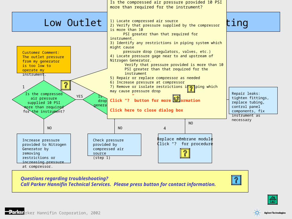
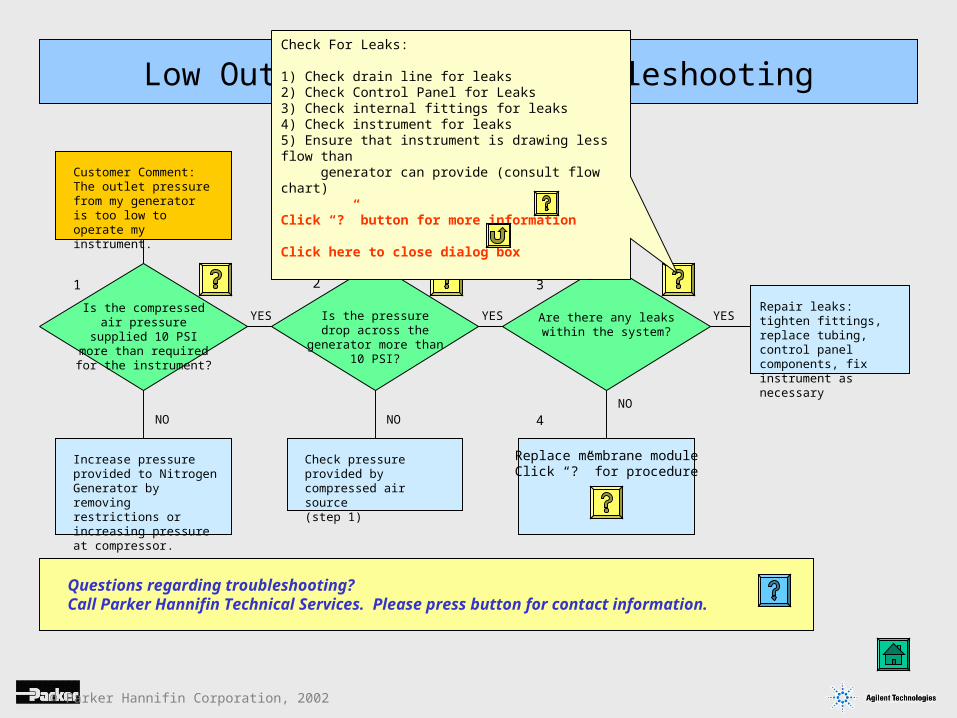
Low Outlet Pressure Troubleshooting
Customer Comment:The outlet pressure from my generator is too low to operate my instrument.
Is the compressed air pressure supplied 10 PSI more than required for the
instrument?
YES
NO NO
Increase pressure provided to Nitrogen Generator by removing restrictions or increasing pressure at compressor.
Check pressure provided by compressed air source(step 1)
1 2
YES Are there any leaks within the system?
NO
YES
3
4
Replace membrane moduleClick “?” for procedure
Repair leaks: tighten fittings, replace tubing, control panel components, fix instrument as necessary
Is the pressure drop across the generator more than 10 PSI?
Questions regarding troubleshooting?Call Parker Hannifin Technical Services. Please press button for contact information.
© Parker Hannifin Corporation, 2002
Is the pressure drop across the generator more than 10 PSI?
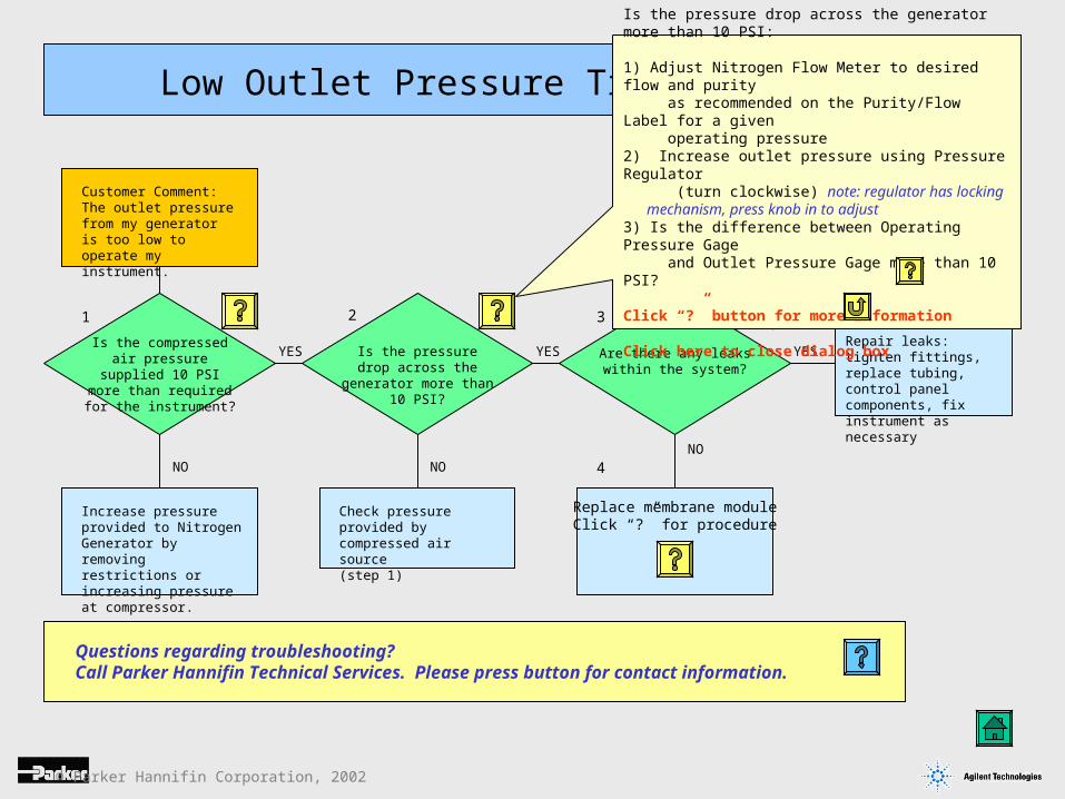
Low Outlet Pressure Troubleshooting
Customer Comment:The outlet pressure from my generator is too low to operate my instrument.
Is the compressed air pressure supplied 10 PSI more than required for the
instrument?
YES
NO NO
Increase pressure provided to Nitrogen Generator by removing restrictions or increasing pressure at compressor.
Check pressure provided by compressed air source(step 1)
1 2
YES Are there any leaks within the system?
NO
YES
3
4
Replace membrane moduleClick “?” for procedure
Is the compressed air pressure provided 10 PSI more than required for the instrument?
1) Locate compressed air source2) Verify that pressure supplied by the compressor is more than 10 PSI greater than that required for instrument.3) Identify any restrictions in piping system which might cause pressure drop (regulators, valves, etc.)4) Locate pressure gage near to and upstream of Nitrogen Generator.
Verify that pressure provided is more than 10 PSI greater than that required for the instrument
5) Repair or replace compressor as needed6) Increase pressure at compressor7) Remove or isolate restrictions in piping which may cause pressure drop
Click “?” button for more information
Click here to close dialog box
Repair leaks: tighten fittings, replace tubing, control panel components, fix instrument as necessary
Questions regarding troubleshooting?Call Parker Hannifin Technical Services. Please press button for contact information.
© Parker Hannifin Corporation, 2002
Repair leaks: tighten fittings, replace tubing, control panel components, fix instrument as necessary
Low Outlet Pressure Troubleshooting
Customer Comment:The outlet pressure from my generator is too low to operate my instrument.
Is the compressed air pressure supplied 10 PSI more than required for the
instrument?
YES
NO NO
Increase pressure provided to Nitrogen Generator by removing restrictions or increasing pressure at compressor.
Check pressure provided by compressed air source(step 1)
1 2
YES Are there any leaks within the system?
NO
YES
3
4
Replace membrane moduleClick “?” for procedure
Is the pressure drop across the generator more than 10 PSI:
1) Adjust Nitrogen Flow Meter to desired flow and purity as recommended on the Purity/Flow Label for a given operating pressure2) Increase outlet pressure using Pressure Regulator (turn clockwise) note: regulator has locking mechanism, press knob in to adjust3) Is the difference between Operating Pressure Gage and Outlet Pressure Gage more than 10 PSI?
Click “?” button for more information
Click here to close dialog box
Is the pressure drop across the generator more than 10 PSI?
Questions regarding troubleshooting?Call Parker Hannifin Technical Services. Please press button for contact information.
© Parker Hannifin Corporation, 2002
Low Outlet Pressure Troubleshooting
Customer Comment:The outlet pressure from my generator is too low to operate my instrument.
Is the compressed air pressure supplied 10 PSI more than required for the
instrument?
YES
NO
Is the pressure drop across the generator more than 10 PSI?
NO
Increase pressure provided to Nitrogen Generator by removing restrictions or increasing pressure at compressor.
Check pressure provided by compressed air source(step 1)
1 2
YES Are there any leaks within the system?
NO
YESRepair leaks: tighten fittings, replace tubing, control panel components, fix instrument as necessary
3
4
Replace membrane moduleClick “?” for procedure
Check For Leaks:
1) Check drain line for leaks2) Check Control Panel for Leaks3) Check internal fittings for leaks4) Check instrument for leaks5) Ensure that instrument is drawing less flow than generator can provide (consult flow chart)
Click “?” button for more information
Click here to close dialog box
Questions regarding troubleshooting?Call Parker Hannifin Technical Services. Please press button for contact information.
© Parker Hannifin Corporation, 2002
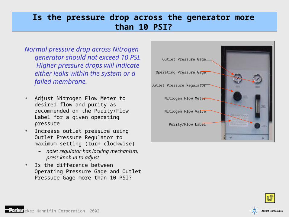
Normal pressure drop across Nitrogen generator should not exceed 10 PSI. Higher pressure drops will indicate either leaks within the system or a failed membrane.
• Adjust Nitrogen Flow Meter to desired flow and purity as recommended on the Purity/Flow Label for a given operating pressure
• Increase outlet pressure using Outlet Pressure Regulator to maximum setting (turn clockwise)
– note: regulator has locking mechanism, press knob in to adjust
• Is the difference between Operating Pressure Gage and Outlet Pressure Gage more than 10 PSI?
Is the pressure drop across the generator more than 10 PSI?
Outlet Pressure Gage
Operating Pressure Gage
Outlet Pressure Regulator
Nitrogen Flow Meter
Nitrogen Flow Valve
Purity/Flow Label
© Parker Hannifin Corporation, 2002
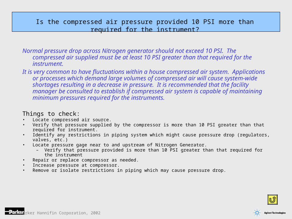
Normal pressure drop across Nitrogen generator should not exceed 10 PSI. The compressed air supplied must be at least 10 PSI greater than that required for the instrument.
It is very common to have fluctuations within a house compressed air system. Applications or processes which demand large volumes of compressed air will cause system-wide shortages resulting in a decrease in pressure. It is recommended that the facility manager be consulted to establish if compressed air system is capable of maintaining minimum pressures required for the instruments.
Things to check:• Locate compressed air source.• Verify that pressure supplied by the compressor is more than 10 PSI greater than that required for instrument.• Identify any restrictions in piping system which might cause pressure drop (regulators, valves, etc.)• Locate pressure gage near to and upstream of Nitrogen Generator.
– Verify that pressure provided is more than 10 PSI greater than that required for the instrument• Repair or replace compressor as needed.• Increase pressure at compressor.• Remove or isolate restrictions in piping which may cause pressure drop.
Is the compressed air pressure provided 10 PSI more than required for the instrument?
© Parker Hannifin Corporation, 2002
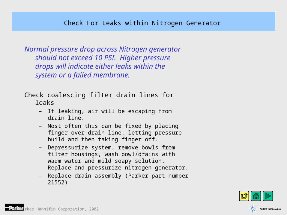
Normal pressure drop across Nitrogen generator should not exceed 10 PSI. Higher pressure drops will indicate either leaks within the system or a failed membrane.
Check coalescing filter drain lines for leaks– If leaking, air will be escaping from drain line.
– Most often this can be fixed by placing finger over drain line, letting pressure build and then taking finger off.
– Depressurize system, remove bowls from filter housings, wash bowl/drains with warm water and mild soapy solution. Replace and pressurize nitrogen generator.
– Replace drain assembly (Parker part number 21552)
Check For Leaks within Nitrogen Generator
© Parker Hannifin Corporation, 2002
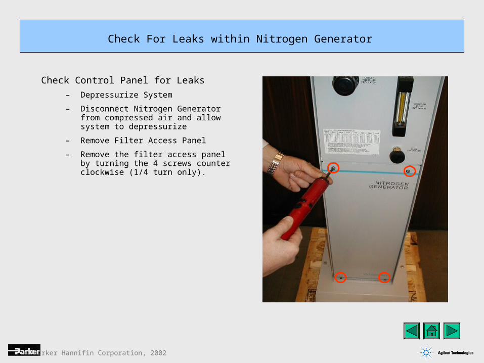
Check Control Panel for Leaks
– Depressurize System
– Disconnect Nitrogen Generator from compressed air and allow system to depressurize
– Remove Filter Access Panel
– Remove the filter access panel by turning the 4 screws counter clockwise (1/4 turn only).
Check For Leaks within Nitrogen Generator
© Parker Hannifin Corporation, 2002
Figure 1
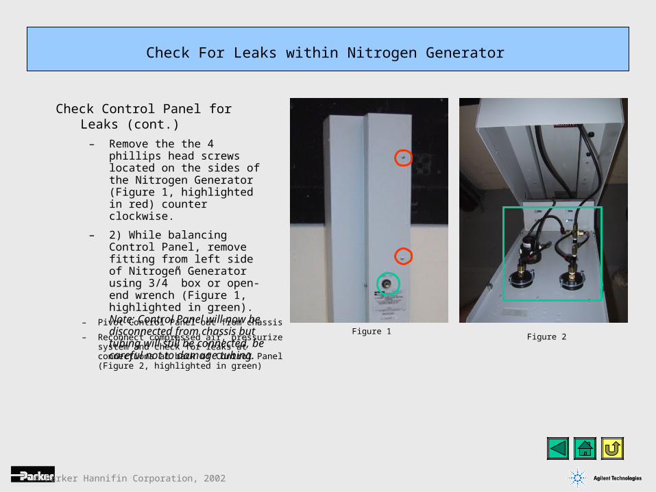
Check Control Panel for Leaks (cont.)
– Remove the the 4 phillips head screws located on the sides of the Nitrogen Generator (Figure 1, highlighted in red) counter clockwise.
– 2) While balancing Control Panel, remove fitting from left side of Nitrogen Generator using 3/4” box or open-end wrench (Figure 1, highlighted in green). Note: Control Panel will now be disconnected from chassis but tubing will still be connected, be careful not to damage tubing.
Check For Leaks within Nitrogen Generator
Figure 2– Pivot Control Panel out from chassis
– Reconnect compressed air, pressurize system and check for leaks at connections at back of Control Panel (Figure 2, highlighted in green)
© Parker Hannifin Corporation, 2002
Membrane Module Replacement:Replacement of the Membrane Module will take approximately 40 minutes. It is recommended that the routine maintenance be performed at the same time. It is very important that you review the quality of the compressed air before performing this procedure. If the compressed air is not of sufficient quality then the membrane is likely to encounter problems again.
Compressed Air ConcernsMost often the cause for Membrane Module failure relates to the quality of the compressed air. It is very important to check that the compressor is not being run at too high a duty cycle. Please consult the compressor manufacturer for specifications for the compressor. Also, it is critical that the compressed air temperature not exceed 77º F (25º C). The reason for the maximum temperature is that the compressed air can contain excessive amounts of water vapour at temperatures above 77º F (25º C). The coalescing prefilters provided with the Nitrogen Generator are designed to remove liquid water, and can not remove water vapour. Liquid water will affect the Membrane Module and will cause premature failure. Please contact Parker Hannifin Analytical Gas Systems Technical Services at 800-343-4048 if you have any questions.
Tools Required:• Phillips head screwdriver• 7/16” socket or nut driver• 3/4” box or open-end wrench
Other Materials needed:Membrane ModuleOptional: Maintenance Kit (includes 3 filters and Carbon Module)
Note about Parker Presto-lock fittings:To disconnect tubing from fittings, press inward (towards body of fitting) on tubing and plastic collar to release tubing from the fitting. While maintaining pressure on plastic collar, remove tubing from fitting. To install tubing, press tubing entirely into fitting to get the best seal.
Membrane Module Replacement
© Parker Hannifin Corporation, 2002
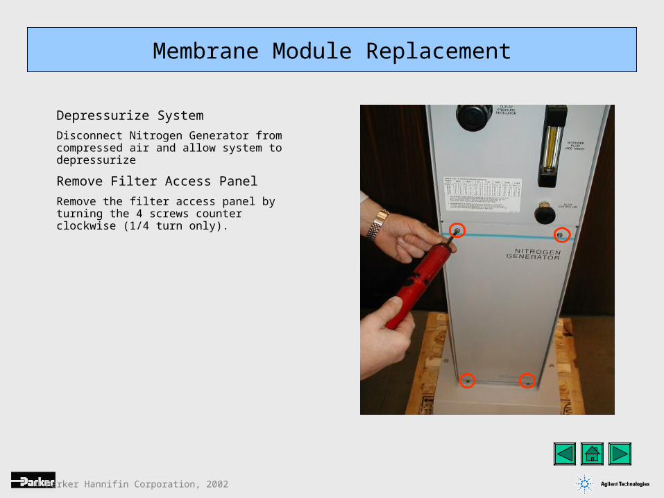
Depressurize System
Disconnect Nitrogen Generator from compressed air and allow system to depressurize
Remove Filter Access Panel
Remove the filter access panel by turning the 4 screws counter clockwise (1/4 turn only).
Membrane Module Replacement
© Parker Hannifin Corporation, 2002
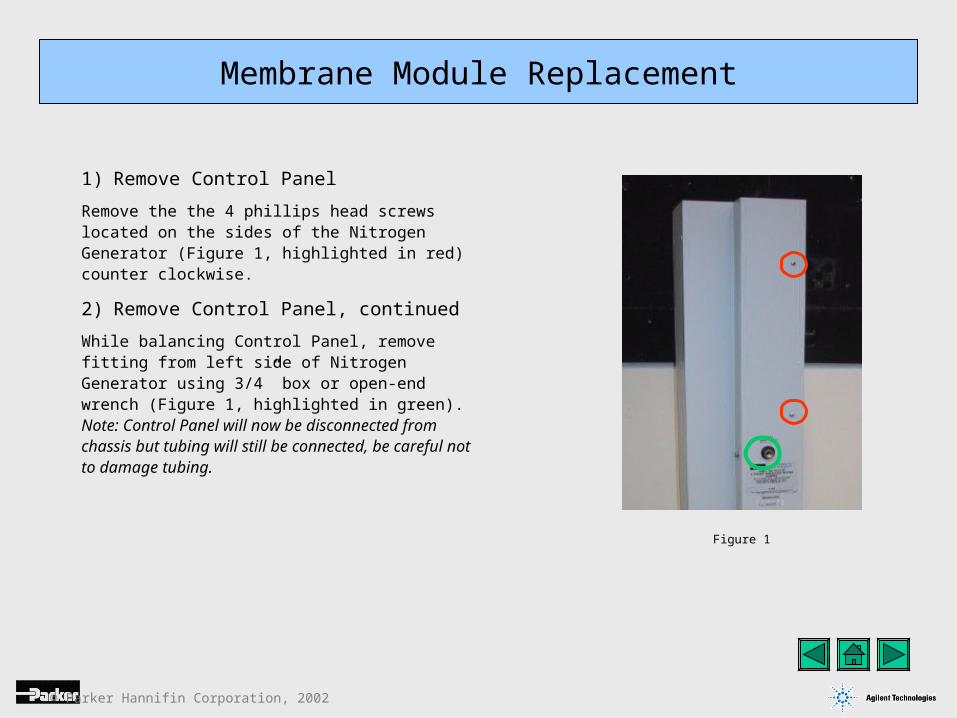
1) Remove Control Panel
Remove the the 4 phillips head screws located on the sides of the Nitrogen Generator (Figure 1, highlighted in red) counter clockwise.
2) Remove Control Panel, continued
While balancing Control Panel, remove fitting from left side of Nitrogen Generator using 3/4” box or open-end wrench (Figure 1, highlighted in green). Note: Control Panel will now be disconnected from chassis but tubing will still be connected, be careful not to damage tubing.
Figure 1
Membrane Module Replacement
© Parker Hannifin Corporation, 2002
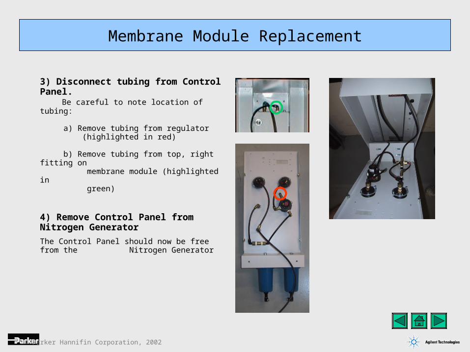
3) Disconnect tubing from Control Panel. Be careful to note location of tubing:
a) Remove tubing from regulator (highlighted in red)
b) Remove tubing from top, right fitting on membrane module (highlighted in green)
4) Remove Control Panel from Nitrogen Generator
The Control Panel should now be free from the Nitrogen Generator
Membrane Module Replacement
© Parker Hannifin Corporation, 2002
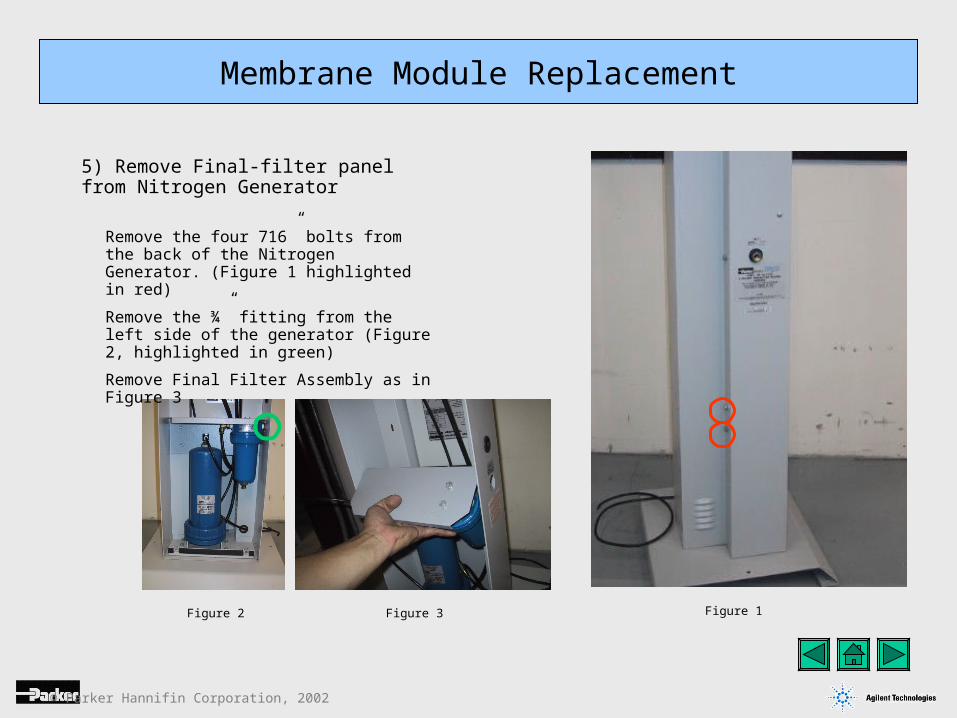
5) Remove Final-filter panel from Nitrogen Generator
Membrane Module Replacement
Figure 3Figure 2 Figure 1
Remove the four 716” bolts from the back of the Nitrogen Generator. (Figure 1 highlighted in red)
Remove the ¾” fitting from the left side of the generator (Figure 2, highlighted in green)
Remove Final Filter Assembly as in Figure 3
© Parker Hannifin Corporation, 2002
Membrane Module Replacement
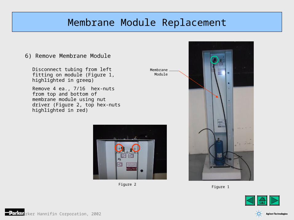
6) Remove Membrane Module
Figure 1Figure 2
Disconnect tubing from left fitting on module (Figure 1, highlighted in green)
Remove 4 ea., 7/16” hex-nuts from top and bottom of membrane module using nut driver (Figure 2, top hex-nuts highlighted in red)
MembraneModule
© Parker Hannifin Corporation, 2002
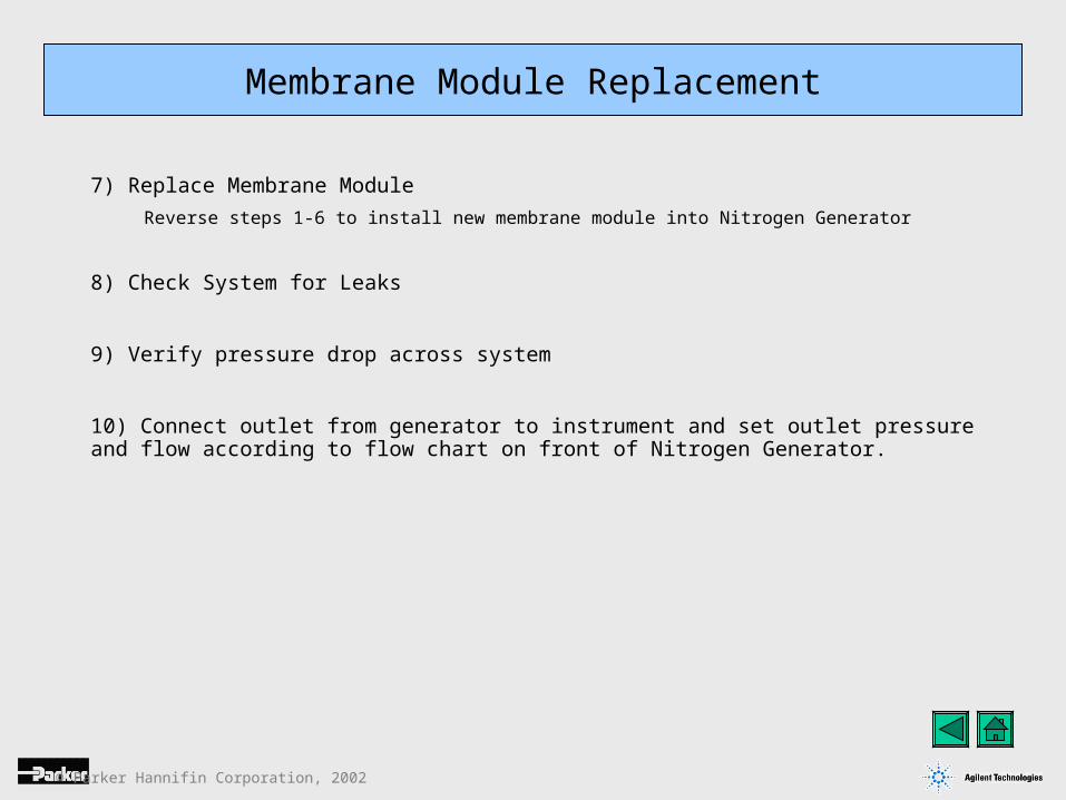
7) Replace Membrane Module
Reverse steps 1-6 to install new membrane module into Nitrogen Generator
8) Check System for Leaks
9) Verify pressure drop across system
10) Connect outlet from generator to instrument and set outlet pressure and flow according to flow chart on front of Nitrogen Generator.
Membrane Module Replacement
© Parker Hannifin Corporation, 2002
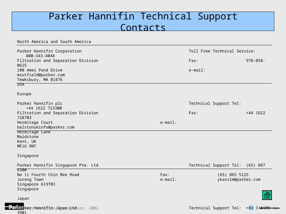
Parker Hannifin Technical Support Contacts
North America and South America
Parker Hannifin Corporation Toll Free Technical Service: 800-343-4048Filtration and Separation Division Fax: 978-858-0625100 Ames Pond Drive e-mail: [email protected], MA 01876USA
Europe Parker Hannifin plc Technical Support Tel: +44 1622 723300Filtration and Separation Division Fax: +44 1622 728703Hermitage Court e-mail: [email protected] Lane MaidstoneKent, UKME16 9NT
Singapore Parker Hannifin Singapore Pte. Ltd. Technical Support Tel: (65) 887 6300No 11 Fourth Chin Bee Road Fax: (65) 865 5125Jorong Town e-mail: [email protected] Singapore 619702Singapore
Japan Parker Hannifin Japan Ltd Technical Support Tel: +81 3 6408 3901626 Totsuka-Cho Fax: +81 3 5449 7202Totsuka-Ku e-mail: [email protected] YohohamaJapan
© Parker Hannifin Corporation, 2002
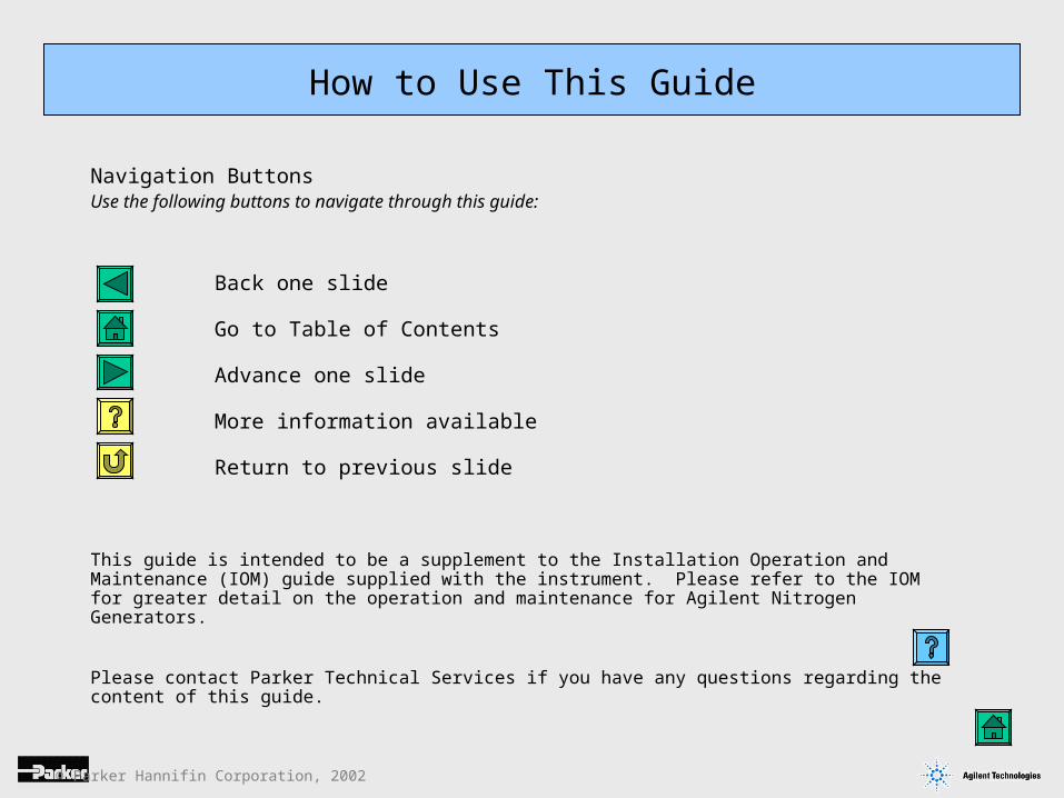
How to Use This Guide
Navigation ButtonsUse the following buttons to navigate through this guide:
Back one slide
Go to Table of Contents
Advance one slide
More information available
Return to previous slide
This guide is intended to be a supplement to the Installation Operation and Maintenance (IOM) guide supplied with the instrument. Please refer to the IOM for greater detail on the operation and maintenance for Agilent Nitrogen Generators.
Please contact Parker Technical Services if you have any questions regarding the content of this guide.
© Parker Hannifin Corporation, 2002
Nitrogen Generator Manuals
Quick Start Summary (English Version)
Full Manual (English Version)
The following manuals can be found on the Service DVD
Related Documents