newsletter OF THE James Clerk Maxwell Foundation, edinburgh Issue No.11 Summer 2018 Wireless Advances using Visible Light (LiFi) By Peter M. Grant, OBE, FREng, FRSE, Trustee and Emeritus Regius Professor of Engineering, University of Edinburgh g Introduction Whether using smartphones or computers, wireless networks allow us to watch videos and communicate with others by email, Facebook or Instagram even while on the move. Existing technology uses wireless cellular communication and WiFi (Wireless-Fidelity). It uses the radio band (RF) of the electromagnetic spectrum (Figure 1). This article looks at existing technology 1 and then at the emerging technology of Visible Light Communication (VLC) known as LiFi (Light-Fidelity). LiFi uses the visible band and Figure 1 shows that the frequencies under LiFi are much higher (and wavelengths correspondingly shorter) than under cellular communication or WiFi. Cellular communication Five billion people worldwide own mobile phones with some two billion of these being smartphones. Smartphones offer internet access via wireless cellular communication. When on the move (e.g. using mobile phones in a car or a train), wireless communication systems are used. In addition, almost two billion sensors (e.g. smart-meters and sensors on autonomous vehicles) are connected to the internet. These networks have necessitated the deployment of more than three million base-stations (radio masts) world-wide. A cellular base-station, in a rural setting, uses ‘macro-cells’ (Figure 2) which serve users situated within a radius of about a ten to twenty kilometres. Base-stations are used to support voice and data communication traffic to and from personal devices. In an urban setting, where user density is higher, smaller cells (‘micro-cells’) are typically used. Figure 3 shows a pavement mounted transmitter plus the associated cabinet. These micro-cells enable individual handsets to reach data-transfer-rates, in 4G systems, of up to 15-20 Mbit/s (million bits of data – ones and zeros – per second). Through advances in technology, this data-transfer-rate is predicted to reach 40 Mbit/s by 2021. International agreement provides for the allocation of specific parts of the electromagnetic spectrum for carrying voice and data traffic. These networks, through a system of licences, exploit Maxwell’s electromagnetic waves in the RF part of the spectrum. Claude Shannon’s seminal work in information theory 3 , shows that the capacity or data-transfer-rate achievable in a wireless link (or network) is directly proportional to the bandwidth 4 of the transmitted signal. Mobile communications suffer from multiple propagation paths as and when the signal (between the transmitter and receiver) is reflected off nearby buildings (Figure 4). At the receiving antenna, these various reflected signals are simply summed (algebraically) at the operating carrier frequency. This results in both constructive and disruptive summation, the latter resulting in a signal loss – known as a ‘deep fade’ . In order to counteract such signal loss, significant channel-modelling software and digital-signal-processing algorithms require to be employed in the receiver. ISSN 2058-7503 (Print) ISSN 2058-7511 (Online) 1 I. A. Glover and P.M. Grant, “Digital Communications”, Pearson Education, 3rd edition, 2013. 2 Millimetre(mm)=10 -3 metres : Nanometre(nm)=10 -9 metres : Megahertz(MHz)=10 6 Hertz : Gigahertz(GHz)=10 9 Hertz : Terrahertz(THz)=10 12 Hertz : Picohertz(PHz)=10 15 Hertz : Exahertz(EHz)=10 18 Hertz 3 C.E. Shannon, “A Mathematical Theory of Communication”, Bell System Technical Journal, Vol. 21, pp. 379-432 and 623-656, 1948. 4 Signal bandwidth, in Hz, depends on transmitted data-transfer-rate and type of modulation and is measured by conducting Fourier analysis. 5 See footnote 1 Band Gamma-ray X-ray Ultraviolet Visible (VLC) Infrared Radio (RF) Wavelength <0.01 nm 0.01-10 nm 10 nm-400 nm 400 nm-750 nm 750 nm-1 mm >1 mm Frequency >30 EHz 30 PHz-30 EHz 790 THz-30 PHz 405 THz-790 THz 300 GHz-405 THz 3 Hz- 300 GHz Figure 1 2 : The electromagnetic spectrum divided into bands Figure 3: A ‘micro-cell’ base-station (which appears like another street lamp) Figure 4: Multiple propagation paths occur where signals are reflected off buildings (courtesy of the Pearson Education 5 ) Figure 2: A ‘macro-cell’ base-station

Welcome message from author
This document is posted to help you gain knowledge. Please leave a comment to let me know what you think about it! Share it to your friends and learn new things together.
Transcript
newsletterOF THE James Clerk Maxwell Foundation, edinburgh
Issue No.11 Summer 2018
Wireless Advances using Visible Light (LiFi) By Peter M. Grant, OBE, FREng, FRSE, Trustee and Emeritus Regius Professor of Engineering, University of Edinburgh
g
IntroductionWhether using smartphones or computers, wireless networksallow us to watch videos and communicate with others byemail, Facebook or Instagram even while on the move.Existing technology uses wireless cellular communication and WiFi (Wireless-Fidelity). It uses the radio band (RF) of theelectromagnetic spectrum (Figure 1). This article looks at existing technology 1 and then at theemerging technology of Visible Light Communication (VLC)known as LiFi (Light-Fidelity). LiFi uses the visible band andFigure 1 shows that the frequencies under LiFi are much higher(and wavelengths correspondingly shorter) than under cellularcommunication or WiFi.
Cellular communicationFive billion people worldwide own mobilephones with some two billion of these beingsmartphones. Smartphones offer internet accessvia wireless cellular communication. When on themove (e.g. using mobile phones in a car or a train),wireless communication systems are used. In addition, almost two billion sensors(e.g. smart-meters and sensors on autonomous vehicles) are connected to the internet. These networks have necessitated the deployment of more than three million base-stations (radio masts) world-wide.
A cellular base-station, in a rural setting, uses ‘macro-cells’ (Figure2) which serve users situated within a radius of about a ten totwenty kilometres. Base-stations are used to support voice anddata communication traffic to and from personal devices.
In an urban setting, whereuser density is higher,smaller cells (‘micro-cells’)are typically used. Figure 3shows a pavement mountedtransmitter plus the associated cabinet. These micro-cells enableindividual handsets to reachdata-transfer-rates, in 4Gsystems, of up to 15-20Mbit/s (million bits of
data – ones and zeros – per second). Through advancesin technology, this data-transfer-rate is predicted to reach 40 Mbit/s by 2021. International agreement provides for the allocation of specificparts of the electromagnetic spectrum for carrying voice and datatraffic. These networks, through a system of licences, exploitMaxwell’s electromagnetic waves in the RF part of the spectrum.Claude Shannon’s seminal work in information theory3, showsthat the capacity or data-transfer-rate achievable in a wirelesslink (or network) is directly proportional to the bandwidth4
of the transmitted signal. Mobile communicationssuffer from multiple propagation paths as and when the signal (between thetransmitter and receiver) is reflected off nearby buildings(Figure 4). At the receiving antenna,these various reflectedsignals are simplysummed (algebraically)
at the operating carrier frequency. This results in both constructive and disruptive summation, the latter resultingin a signal loss – known as a ‘deep fade’. In order to counteract such signal loss, significant channel-modelling software and digital-signal-processing algorithms require to be employedin the receiver.
ISSN 2058-7503 (Print)ISSN 2058-7511 (Online)
1 I. A. Glover and P.M. Grant, “Digital Communications”, Pearson Education, 3rd edition, 2013.2 Millimetre(mm)=10-3 metres : Nanometre(nm)=10-9 metres : Megahertz(MHz)=106 Hertz : Gigahertz(GHz)=109 Hertz : Terrahertz(THz)=1012 Hertz : Picohertz(PHz)=1015
Hertz : Exahertz(EHz)=1018 Hertz3 C.E. Shannon, “A Mathematical Theory of Communication”, Bell System Technical Journal, Vol. 21, pp. 379-432 and 623-656, 1948.4 Signal bandwidth, in Hz, depends on transmitted data-transfer-rate and type of modulation and is measured by conducting Fourier analysis. 5 See footnote 1
BandGamma-ray
X-rayUltraviolet
Visible (VLC)Infrared
Radio (RF)
Wavelength<0.01 nm
0.01-10 nm10 nm-400 nm
400 nm-750 nm750 nm-1 mm
>1 mm
Frequency>30 EHz
30 PHz-30 EHz790 THz-30 PHz
405 THz-790 THz300 GHz-405 THz
3 Hz- 300 GHz
Figure 12: The electromagnetic spectrum divided into bands
Figure 3: A ‘micro-cell’ base-station(which appears like another street lamp)
Figure 4: Multiple propagation paths occurwhere signals are reflected off buildings(courtesy of the Pearson Education5) Figure 2:
A ‘macro-cell’ base-station
newsletterOF THE James Clerk Maxwell Foundation, edinburgh
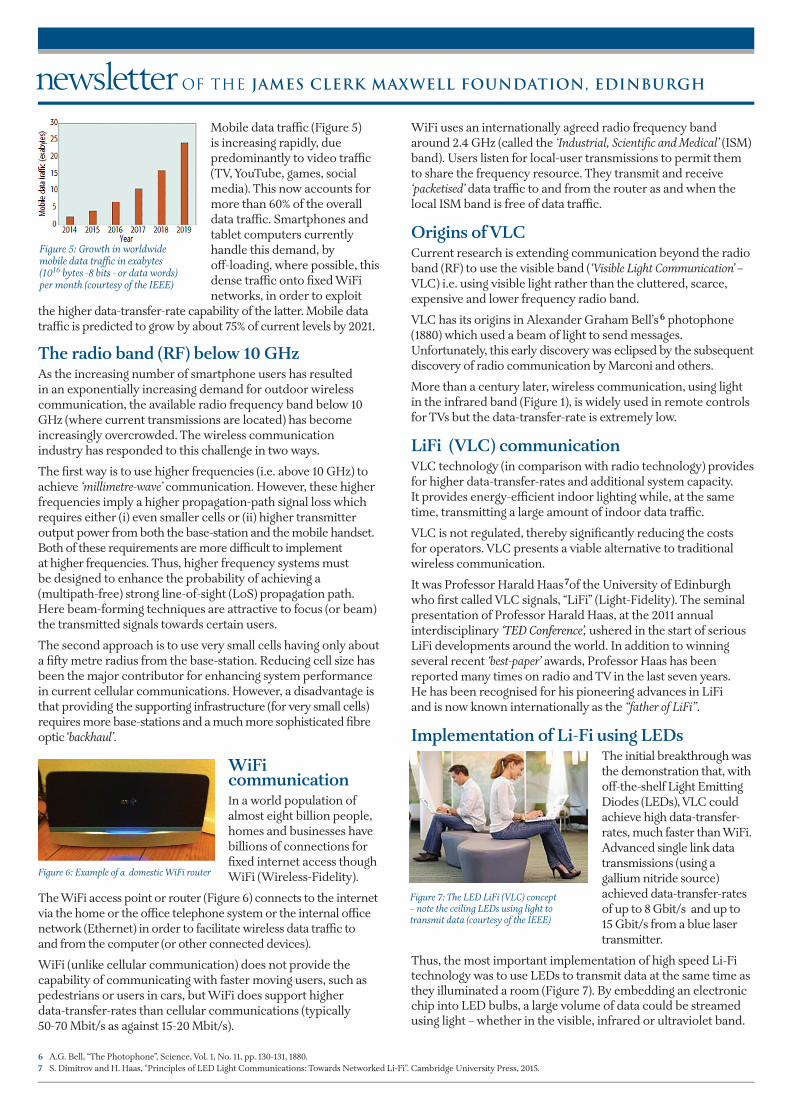
Mobile data traffic (Figure 5)is increasing rapidly, due predominantly to video traffic(TV, YouTube, games, socialmedia). This now accounts formore than 60% of the overalldata traffic. Smartphones andtablet computers currently handle this demand, by off-loading, where possible, thisdense traffic onto fixed WiFi networks, in order to exploit
the higher data-transfer-rate capability of the latter. Mobile data traffic is predicted to grow by about 75% of current levels by 2021.
The radio band (RF) below 10 GHz As the increasing number of smartphone users has resultedin an exponentially increasing demand for outdoor wirelesscommunication, the available radio frequency band below 10GHz (where current transmissions are located) has becomeincreasingly overcrowded. The wireless communicationindustry has responded to this challenge in two ways.
The first way is to use higher frequencies (i.e. above 10 GHz) toachieve ‘millimetre-wave’ communication. However, these higherfrequencies imply a higher propagation-path signal loss whichrequires either (i) even smaller cells or (ii) higher transmitteroutput power from both the base-station and the mobile handset.Both of these requirements are more difficult to implementat higher frequencies. Thus, higher frequency systems mustbe designed to enhance the probability of achieving a(multipath-free) strong line-of-sight (LoS) propagation path.Here beam-forming techniques are attractive to focus (or beam)the transmitted signals towards certain users.
The second approach is to use very small cells having only abouta fifty metre radius from the base-station. Reducing cell size hasbeen the major contributor for enhancing system performancein current cellular communications. However, a disadvantage isthat providing the supporting infrastructure (for very small cells)requires more base-stations and a much more sophisticated fibreoptic ‘backhaul’.
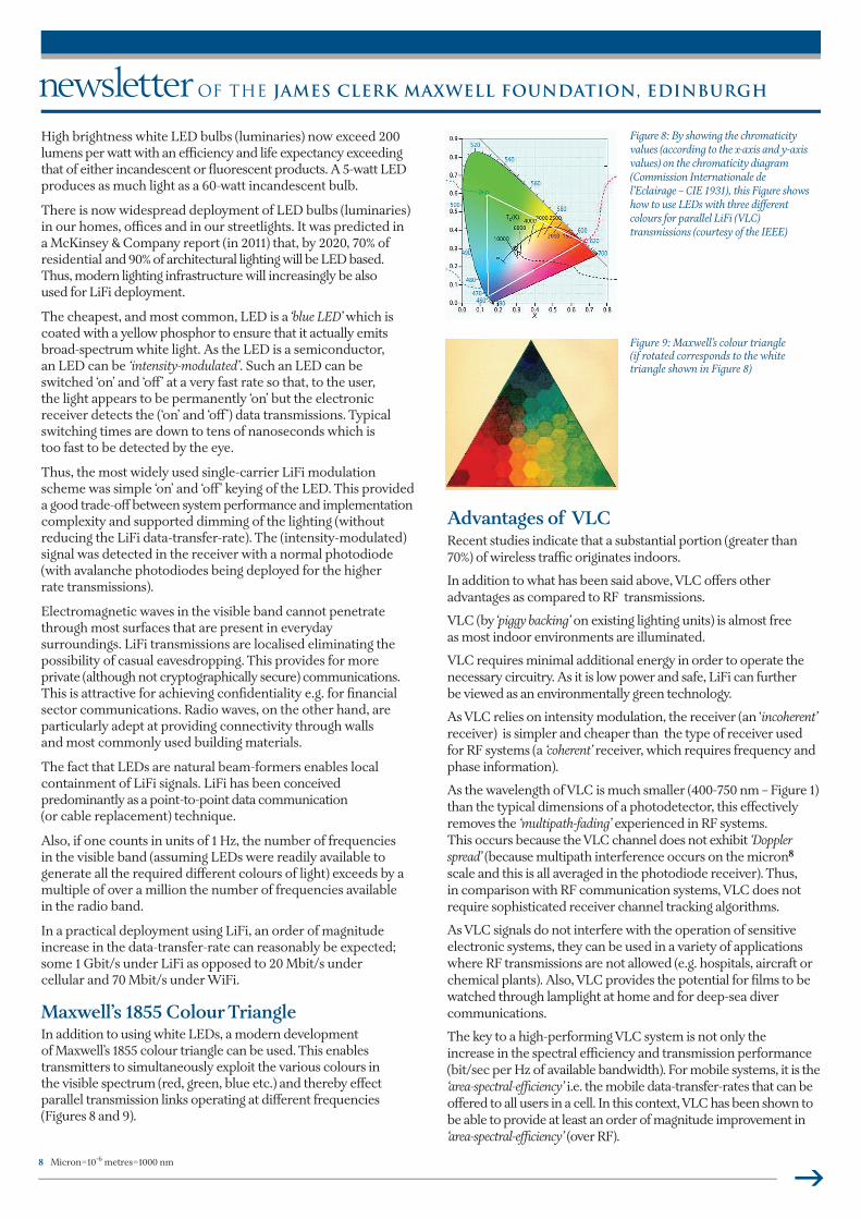
WiFi communicationIn a world population of almost eight billion people,homes and businesses havebillions of connections forfixed internet access thoughWiFi (Wireless-Fidelity).
The WiFi access point or router (Figure 6) connects to the internetvia the home or the office telephone system or the internal officenetwork (Ethernet) in order to facilitate wireless data traffic to and from the computer (or other connected devices).
WiFi (unlike cellular communication) does not provide the capability of communicating with faster moving users, such aspedestrians or users in cars, but WiFi does support higher data-transfer-rates than cellular communications (typically 50-70 Mbit/s as against 15-20 Mbit/s).
WiFi uses an internationally agreed radio frequency bandaround 2.4 GHz (called the ‘Industrial, Scientific and Medical’ (ISM)band). Users listen for local-user transmissions to permit themto share the frequency resource. They transmit and receive‘packetised’ data traffic to and from the router as and when thelocal ISM band is free of data traffic.
Origins of VLCCurrent research is extending communication beyond the radioband (RF) to use the visible band (‘Visible Light Communication’ –VLC) i.e. using visible light rather than the cluttered, scarce, expensive and lower frequency radio band.
VLC has its origins in Alexander Graham Bell’s6 photophone(1880) which used a beam of light to send messages. Unfortunately, this early discovery was eclipsed by the subsequentdiscovery of radio communication by Marconi and others.
More than a century later, wireless communication, using lightin the infrared band (Figure 1), is widely used in remote controlsfor TVs but the data-transfer-rate is extremely low.
LiFi (VLC) communicationVLC technology (in comparison with radio technology) providesfor higher data-transfer-rates and additional system capacity.It provides energy-efficient indoor lighting while, at the sametime, transmitting a large amount of indoor data traffic.
VLC is not regulated, thereby significantly reducing the costs for operators. VLC presents a viable alternative to traditionalwireless communication.
It was Professor Harald Haas7of the University of Edinburghwho first called VLC signals, “LiFi” (Light-Fidelity). The seminalpresentation of Professor Harald Haas, at the 2011 annual interdisciplinary ‘TED Conference’, ushered in the start of seriousLiFi developments around the world. In addition to winning several recent ‘best-paper’ awards, Professor Haas has been reported many times on radio and TV in the last seven years. He has been recognised for his pioneering advances in LiFi and is now known internationally as the “father of LiFi”.
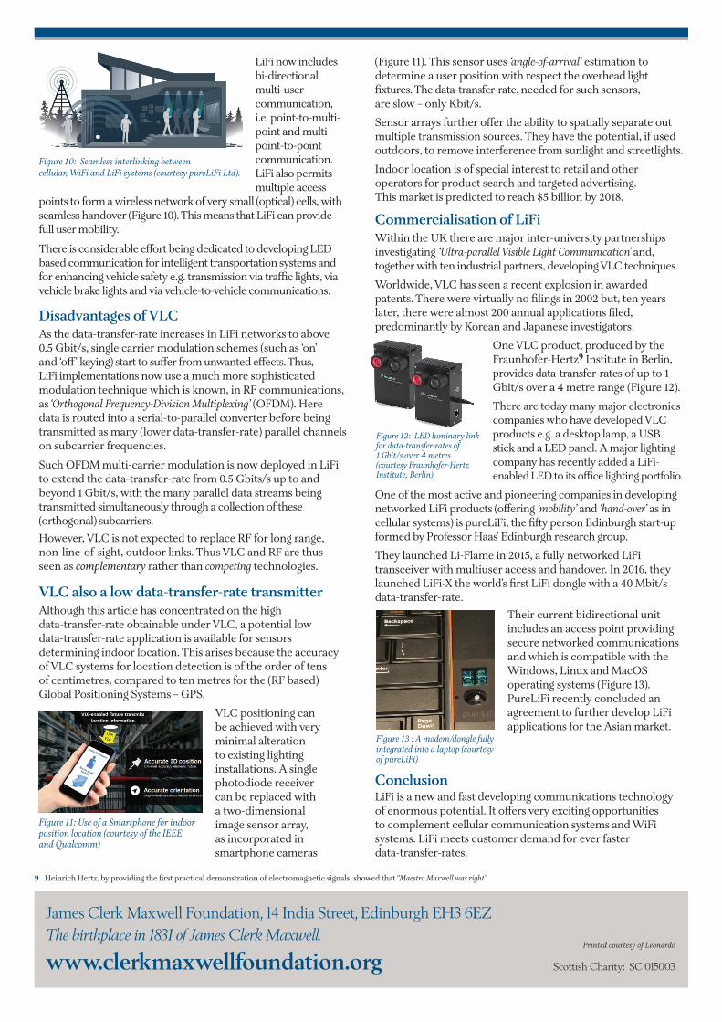
Implementation of Li-Fi using LEDsThe initial breakthrough was the demonstration that, with off-the-shelf Light EmittingDiodes (LEDs), VLC couldachieve high data-transfer-rates, much faster than WiFi.Advanced single link datatransmissions (using a gallium nitride source)achieved data-transfer-ratesof up to 8 Gbit/s and up to15 Gbit/s from a blue lasertransmitter.
Thus, the most important implementation of high speed Li-Fitechnology was to use LEDs to transmit data at the same time asthey illuminated a room (Figure 7). By embedding an electronicchip into LED bulbs, a large volume of data could be streamedusing light – whether in the visible, infrared or ultraviolet band.
6 A.G. Bell, “The Photophone”, Science, Vol. 1, No. 11, pp. 130-131, 1880.7 S. Dimitrov and H. Haas, “Principles of LED Light Communications: Towards Networked Li-Fi”. Cambridge University Press, 2015.
Figure 5: Growth in worldwidemobile data traffic in exabytes(1016 bytes -8 bits - or data words)per month (courtesy of the IEEE)
Figure 6: Example of a domestic WiFi router
Figure 7: The LED LiFi (VLC) concept – note the ceiling LEDs using light to transmit data (courtesy of the IEEE)
newsletterOF THE James Clerk Maxwell Foundation, edinburgh
g
High brightness white LED bulbs (luminaries) now exceed 200lumens per watt with an efficiency and life expectancy exceedingthat of either incandescent or fluorescent products. A 5-watt LED produces as much light as a 60-watt incandescent bulb.
There is now widespread deployment of LED bulbs (luminaries)in our homes, offices and in our streetlights. It was predicted in a McKinsey & Company report (in 2011) that, by 2020, 70% of residential and 90% of architectural lighting will be LED based.Thus, modern lighting infrastructure will increasingly be also used for LiFi deployment.
The cheapest, and most common, LED is a ‘blue LED’ which iscoated with a yellow phosphor to ensure that it actually emitsbroad-spectrum white light. As the LED is a semiconductor,an LED can be ‘intensity-modulated’. Such an LED can beswitched ‘on’ and ‘off’ at a very fast rate so that, to the user, the light appears to be permanently ‘on’ but the electronic receiver detects the (‘on’ and ‘off’) data transmissions. Typicalswitching times are down to tens of nanoseconds which is too fast to be detected by the eye.
Thus, the most widely used single-carrier LiFi modulationscheme was simple ‘on’ and ‘off’ keying of the LED. This provideda good trade-off between system performance and implementationcomplexity and supported dimming of the lighting (without reducing the LiFi data-transfer-rate). The (intensity-modulated)signal was detected in the receiver with a normal photodiode(with avalanche photodiodes being deployed for the higher rate transmissions).
Electromagnetic waves in the visible band cannot penetratethrough most surfaces that are present in everyday surroundings. LiFi transmissions are localised eliminating the possibility of casual eavesdropping. This provides for more private (although not cryptographically secure) communications.This is attractive for achieving confidentiality e.g. for financialsector communications. Radio waves, on the other hand, areparticularly adept at providing connectivity through walls and most commonly used building materials.
The fact that LEDs are natural beam-formers enables local containment of LiFi signals. LiFi has been conceived predominantly as a point-to-point data communication(or cable replacement) technique.
Also, if one counts in units of 1 Hz, the number of frequenciesin the visible band (assuming LEDs were readily available to generate all the required different colours of light) exceeds by amultiple of over a million the number of frequencies availablein the radio band.
In a practical deployment using LiFi, an order of magnitude increase in the data-transfer-rate can reasonably be expected;some 1 Gbit/s under LiFi as opposed to 20 Mbit/s under cellular and 70 Mbit/s under WiFi.
Maxwell’s 1855 Colour TriangleIn addition to using white LEDs, a modern development of Maxwell’s 1855 colour triangle can be used. This enables transmitters to simultaneously exploit the various colours inthe visible spectrum (red, green, blue etc.) and thereby effect parallel transmission links operating at different frequencies(Figures 8 and 9).
Advantages of VLCRecent studies indicate that a substantial portion (greater than70%) of wireless traffic originates indoors.
In addition to what has been said above, VLC offers otheradvantages as compared to RF transmissions.
VLC (by ‘piggy backing’ on existing lighting units) is almost freeas most indoor environments are illuminated.
VLC requires minimal additional energy in order to operate thenecessary circuitry. As it is low power and safe, LiFi can further be viewed as an environmentally green technology.
As VLC relies on intensity modulation, the receiver (an ‘incoherent’ receiver) is simpler and cheaper than the type of receiver usedfor RF systems (a ‘coherent’ receiver, which requires frequency andphase information).
As the wavelength of VLC is much smaller (400-750 nm – Figure 1) than the typical dimensions of a photodetector, this effectively removes the ‘multipath-fading’ experienced in RF systems. This occurs because the VLC channel does not exhibit ‘Dopplerspread’ (because multipath interference occurs on the micron8
scale and this is all averaged in the photodiode receiver). Thus,in comparison with RF communication systems, VLC does not require sophisticated receiver channel tracking algorithms.
As VLC signals do not interfere with the operation of sensitive electronic systems, they can be used in a variety of applicationswhere RF transmissions are not allowed (e.g. hospitals, aircraft orchemical plants). Also, VLC provides the potential for films to bewatched through lamplight at home and for deep-sea diver communications.
The key to a high-performing VLC system is not only the increase in the spectral efficiency and transmission performance(bit/sec per Hz of available bandwidth). For mobile systems, it is the‘area-spectral-efficiency’ i.e. the mobile data-transfer-rates that can beoffered to all users in a cell. In this context, VLC has been shown tobe able to provide at least an order of magnitude improvement in‘area-spectral-efficiency’ (over RF).
Figure 8: By showing the chromaticity values (according to the x-axis and y-axisvalues) on the chromaticity diagram(Commission Internationale de l’Eclairage – CIE 1931), this Figure showshow to use LEDs with three differentcolours for parallel LiFi (VLC) transmissions (courtesy of the IEEE)
Figure 9: Maxwell’s colour triangle(if rotated corresponds to the whitetriangle shown in Figure 8)
8 Micron=10-6 metres=1000 nm
James Clerk Maxwell Foundation, 14 India Street, Edinburgh EH3 6EZThe birthplace in 1831 of James Clerk Maxwell.
www.clerkmaxwellfoundation.org Scottish Charity: SC 015003
Printed courtesy of Leonardo
LiFi now includesbi-directionalmulti-user communication,i.e. point-to-multi-point and multi-point-to-pointcommunication.LiFi also permitsmultiple access
points to form a wireless network of very small (optical) cells, withseamless handover (Figure 10). This means that LiFi can providefull user mobility.
There is considerable effort being dedicated to developing LEDbased communication for intelligent transportation systems andfor enhancing vehicle safety e.g. transmission via traffic lights, viavehicle brake lights and via vehicle-to-vehicle communications.
Disadvantages of VLCAs the data-transfer-rate increases in LiFi networks to above 0.5 Gbit/s, single carrier modulation schemes (such as ‘on’ and ‘off’ keying) start to suffer from unwanted effects. Thus, LiFi implementations now use a much more sophisticated modulation technique which is known, in RF communications,as ‘Orthogonal Frequency-Division Multiplexing’ (OFDM). Here data is routed into a serial-to-parallel converter before being transmitted as many (lower data-transfer-rate) parallel channelson subcarrier frequencies.
Such OFDM multi-carrier modulation is now deployed in LiFito extend the data-transfer-rate from 0.5 Gbits/s up to and beyond 1 Gbit/s, with the many parallel data streams beingtransmitted simultaneously through a collection of these(orthogonal) subcarriers.However, VLC is not expected to replace RF for long range, non-line-of-sight, outdoor links. Thus VLC and RF are thus seen as complementary rather than competing technologies.
VLC also a low data-transfer-rate transmitterAlthough this article has concentrated on the high data-transfer-rate obtainable under VLC, a potential low data-transfer-rate application is available for sensors determining indoor location. This arises because the accuracyof VLC systems for location detection is of the order of tens of centimetres, compared to ten metres for the (RF based)Global Positioning Systems – GPS.
VLC positioning can be achieved with very minimal alterationto existing lightinginstallations. A single photodiode receiver can be replaced with a two-dimensional image sensor array, as incorporated in smartphone cameras
(Figure 11). This sensor uses ‘angle-of-arrival’ estimation to determine a user position with respect the overhead light fixtures. The data-transfer-rate, needed for such sensors, are slow – only Kbit/s.
Sensor arrays further offer the ability to spatially separate out multiple transmission sources. They have the potential, if used outdoors, to remove interference from sunlight and streetlights.
Indoor location is of special interest to retail and other operators for product search and targeted advertising. This market is predicted to reach $5 billion by 2018.
Commercialisation of LiFiWithin the UK there are major inter-university partnerships investigating ‘Ultra-parallel Visible Light Communication’ and, together with ten industrial partners, developing VLC techniques.
Worldwide, VLC has seen a recent explosion in awardedpatents. There were virtually no filings in 2002 but, ten yearslater, there were almost 200 annual applications filed, predominantly by Korean and Japanese investigators.
One VLC product, produced by theFraunhofer-Hertz9 Institute in Berlin,provides data-transfer-rates of up to 1Gbit/s over a 4 metre range (Figure 12).
There are today many major electronicscompanies who have developed VLCproducts e.g. a desktop lamp, a USBstick and a LED panel. A major lightingcompany has recently added a LiFi-enabled LED to its office lighting portfolio.
One of the most active and pioneering companies in developingnetworked LiFi products (offering ‘mobility’ and ‘hand-over’ as incellular systems) is pureLiFi, the fifty person Edinburgh start-upformed by Professor Haas’ Edinburgh research group.
They launched Li-Flame in 2015, a fully networked LiFi transceiver with multiuser access and handover. In 2016, theylaunched LiFi-X the world’s first LiFi dongle with a 40 Mbit/sdata-transfer-rate.
Their current bidirectional unitincludes an access point providingsecure networked communicationsand which is compatible with theWindows, Linux and MacOS operating systems (Figure 13).PureLiFi recently concluded anagreement to further develop LiFiapplications for the Asian market.
ConclusionLiFi is a new and fast developing communications technologyof enormous potential. It offers very exciting opportunities to complement cellular communication systems and WiFi systems. LiFi meets customer demand for ever faster data-transfer-rates.
Figure 11: Use of a Smartphone for indoorposition location (courtesy of the IEEE and Qualcomm)
Figure 12: LED luminary linkfor data-transfer-rates of 1 Gbit/s over 4 metres(courtesy Fraunhofer-HertzInstitute, Berlin)
Figure 13 : A modem/dongle fullyintegrated into a laptop (courtesyof pureLiFi)
9 Heinrich Hertz, by providing the first practical demonstration of electromagnetic signals, showed that“Maestro Maxwell was right”.
Figure 10: Seamless interlinking betweencellular, WiFi and LiFi systems (courtesy pureLiFi Ltd).
Related Documents