VESA DDC/CI Standard Page 1 of 42 ©Copyright 1997-2004 Video Electronics Standards Association Version 1.1 ©Copyright 1997-2004 Video Electronics Standards Association Version 1.1 DDC/CI ™ Standard 39899 Balentine Drive, Suite 125 Phone: 510 651 5122 Newark, CA 94560 Fax: 510 651 5127 Display Data Channel Command Interface Standard Version 1.1 October 29, 2004 Purpose Define an I 2 C ™ based protocol which operates over the DDC channel to provide interactive control of a display and, optional associated devices. Summary In response to the Plug and Play needs of end-users, VESA has defined the E-DDC standard with different levels of communication. DDC/CI (formerly known as DDC2Bi) provides bi-directional communication between the host and the display. The communication interface is independent of display technology (CRT, LCD, PDP, etc), and is compatible with a number of different video interfaces (VGA, DVI, HDMI, etc).

Welcome message from author
This document is posted to help you gain knowledge. Please leave a comment to let me know what you think about it! Share it to your friends and learn new things together.
Transcript
VESA DDC/CI Standard Page 1 of 42 ©Copyright 1997-2004 Video Electronics Standards Association Version 1.1 ©Copyright 1997-2004 Video Electronics Standards Association Version 1.1
DDC/CI ™ Standard 39899 Balentine Drive, Suite 125 Phone: 510 651 5122 Newark, CA 94560 Fax: 510 651 5127
Display Data Channel Command Interface Standard Version 1.1
October 29, 2004
Purpose Define an I2C ™ based protocol which operates over the DDC channel to provide interactive control of a display and, optional associated devices. Summary
In response to the Plug and Play needs of end-users, VESA has defined the E-DDC standard with different levels of communication. DDC/CI (formerly known as DDC2Bi) provides bi-directional communication between the host and the display. The communication interface is independent of display technology (CRT, LCD, PDP, etc), and is compatible with a number of different video interfaces (VGA, DVI, HDMI, etc).
VESA DDC/CI Standard Page 2 of 42 ©Copyright 1997-2004 Video Electronics Standards Association Version 1.1 ©Copyright 1997-2004 Video Electronics Standards Association Version 1.1
PREFACE Scope This revision of the DDC/CI Standard is intended to extend the E-DDC standard by providing flexibility and expandability for the DDC implementations in many video interfaces. DDC/CI providing a bi-directional communication channel that can be used, along with the VESA Monitor Command and Control Set (MCCS) standard, to provide interactive control of a display. Intellectual Property Copyright © 1998 - 2004, Video Electronics Standards Association. All rights reserved. While every precaution has been taken in the preparation of this standard, the Video Electronics Standards Association and its contributors assume no responsibility for errors or omissions, and make no warranties, expressed or implied, of functionality or suitability for any purpose. Trademarks All trademarks used within this document are the property of their respective owners. VESA, DDC, DPMS, E-DDC, EDID, E-EDID, MCCS and VDIF are trademarks of the Video Electronics Standards Association. I2C is a trademark owned by Philips. HDMI is a trademark of HDMI Licensing, LLC DVI is a trademark of the Digital Display Working Group Patents VESA proposals and standards are adopted by the Video Electronics Standards Association without regard to whether their adoption may involve any patents on articles, materials, or processes. Such adoption does not assume any liability to any patent owner, nor does it assume any obligation whatever to parties adopting the proposals or standards documents. Support for this Standard Clarifications and application notes to support this standard may be written. To obtain the latest standard and any support documentation, contact VESA. If you have a product which incorporates DDC/CI, you should ask the company that manufactured your product for assistance. If you are a manufacturer, VESA can assist you with any clarification you may require. All comments or reported errors should be submitted in writing to VESA using one of the following methods. • Fax 510 651 5127, direct this note to Technical Support at VESA • e-mail [email protected] (with subject: DDC/CI) • mail to Technical Support VESA - Video Electronics Standards Association 39899 Balentine Drive, Suite 125 Newark, CA 94560
VESA DDC/CI Standard Page 3 of 42 ©Copyright 1997-2004 Video Electronics Standards Association Version 1.1 ©Copyright 1997-2004 Video Electronics Standards Association Version 1.1
Revision History Version 1 August 14, 1998 Initial release of the standard Version 1.1 October 29, 2004 Major reorganization and expansion of sections that detail command structures Added support for “table class” of VCP commands Appendix on color adjustment deleted Appendix added on possible problems if DDC/CI and HDCP (High Definition Content Protection) are both being used. Support for EDID within the capability string eliminated Power management priority given to DPM (over DPMS)
VESA DDC/CI Standard Page 4 of 42 ©Copyright 1997-2004 Video Electronics Standards Association Version 1.1 ©Copyright 1997-2004 Video Electronics Standards Association Version 1.1
Acknowledgments This document would not have been possible without the efforts of the VESA Display Systems Standards (former Display) and Japan Committees. In particular, the following individuals and their companies contributed significant time and knowledge. Ian Miller Samsung DDC/CI Task Group Chair Syed Athar Hussain ATI Technologies Inc. Bryan Speece Entech Taiwan Eiichi Mori Fujitsu Eiji Kurimoto Fujitsu Shinji Tsutsumi Fujitsu Yuichiro Wada Fujitsu Graham Loveridge Genesis Microchip Moriyoshi Ohara IBM Japan Shiro Makino EIZO NANAO Tadahiko Hiraka EIZO NANAO Takuma Ishida EIZO NANAO Hiroaki Sugiura Mitsubishi Yoshifumi Sato NEC Plasma Display Jack Hosek NEC-Mitsubishi (US) William Hollingworth NEC-Mitsubishi (US) Hideki Tanizoe NEC-Mitsubishi Kazuaki Takamoto NEC-Mitsubishi Kazuyuki Iimura NEC-Mitsubishi Takashi Katagiri NEC-Mitsubishi Kouichi Ara NEC-Viewtechnology Takashi Nirasawa NEC-Viewtechnology Yoshihisa Kudou NEC-Viewtechnology Isaac Yang NVIDIA Masafumi Ikeda Pioneer Corp Michael Anderson Portrait Displays Inc. Keijiro Naito Seiko Epson Shinji Kubota Seiko Epson Chikaho Abe Sony Satoru Suzuki Sony Shigeru Takasu Sony Steve Hasegawa Sony Joe Lamm Tech Source Katsuki Hazama THine Electronics Mitsugu Yui Totoku Electric Co. Ltd. Alain d’Hautecourt ViewSonic
VESA DDC/CI Standard Page 5 of 42 ©Copyright 1997-2004 Video Electronics Standards Association Version 1.1 ©Copyright 1997-2004 Video Electronics Standards Association Version 1.1
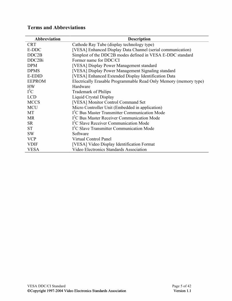
Terms and Abbreviations
Abbreviation Description CRT Cathode Ray Tube (display technology type) E-DDC [VESA] Enhanced Display Data Channel (serial communication) DDC2B Simplest of the DDC2B modes defined in VESA E-DDC standard DDC2Bi Former name for DDC/CI DPM [VESA] Display Power Management standard DPMS [VESA] Display Power Management Signaling standard E-EDID [VESA] Enhanced Extended Display Identification Data EEPROM Electrically Erasable Programmable Read Only Memory (memory type) HW Hardware I2C Trademark of Philips LCD Liquid Crystal Display MCCS [VESA] Monitor Control Command Set MCU Micro Controller Unit (Embedded in application) MT I2C Bus Master Transmitter Communication Mode MR I2C Bus Master Receiver Communication Mode SR I2C Slave Receiver Communication Mode ST I2C Slave Transmitter Communication Mode SW Software VCP Virtual Control Panel VDIF [VESA] Video Display Identification Format VESA Video Electronics Standards Association
VESA DDC/CI Standard Page 6 of 42 ©Copyright 1997-2004 Video Electronics Standards Association Version 1.1 ©Copyright 1997-2004 Video Electronics Standards Association Version 1.1
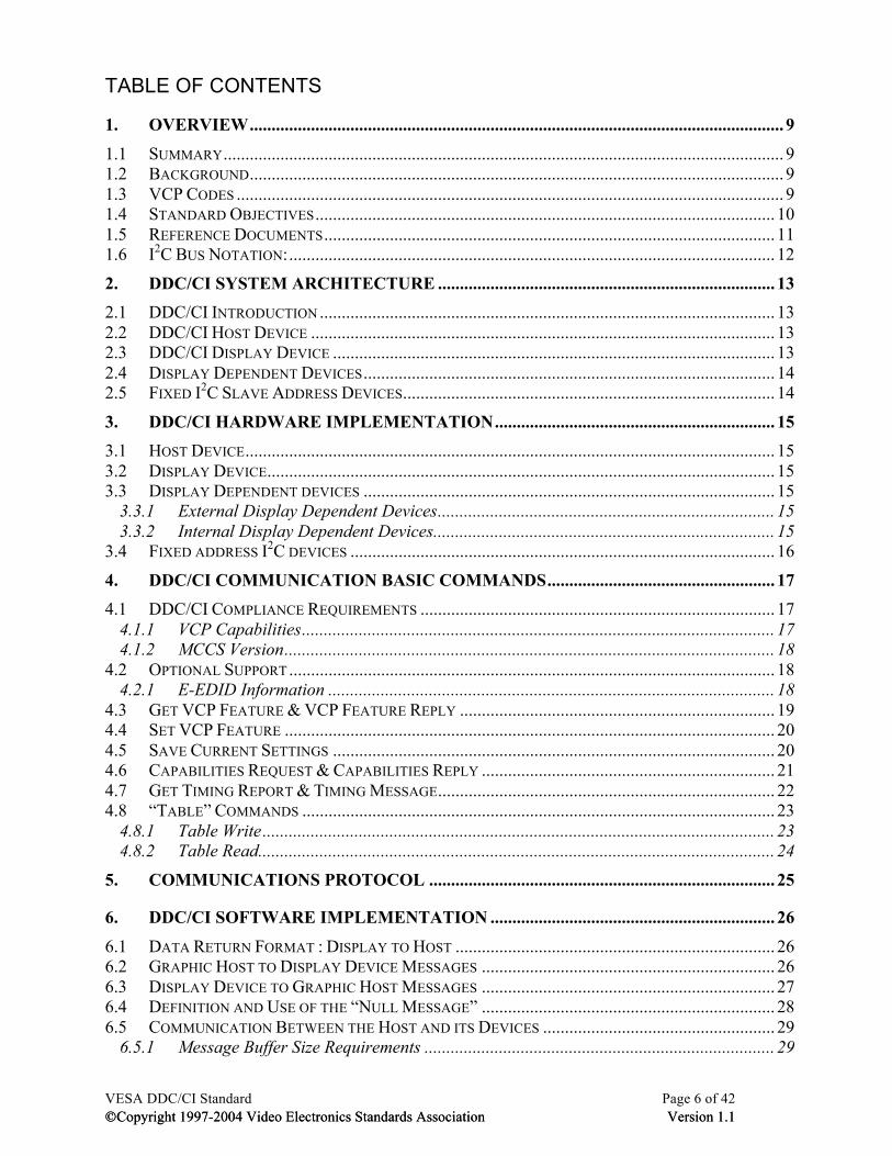
TABLE OF CONTENTS
1. OVERVIEW .......................................................................................................................... 9
1.1 SUMMARY ................................................................................................................................ 9 1.2 BACKGROUND .......................................................................................................................... 9 1.3 VCP CODES ............................................................................................................................. 9 1.4 STANDARD OBJECTIVES ......................................................................................................... 10 1.5 REFERENCE DOCUMENTS ....................................................................................................... 11 1.6 I2C BUS NOTATION: ............................................................................................................... 12
2. DDC/CI SYSTEM ARCHITECTURE ............................................................................. 13 2.1 DDC/CI INTRODUCTION ........................................................................................................ 13 2.2 DDC/CI HOST DEVICE .......................................................................................................... 13 2.3 DDC/CI DISPLAY DEVICE ..................................................................................................... 13 2.4 DISPLAY DEPENDENT DEVICES .............................................................................................. 14 2.5 FIXED I2C SLAVE ADDRESS DEVICES ..................................................................................... 14
3. DDC/CI HARDWARE IMPLEMENTATION ................................................................ 15 3.1 HOST DEVICE ......................................................................................................................... 15 3.2 DISPLAY DEVICE .................................................................................................................... 15 3.3 DISPLAY DEPENDENT DEVICES .............................................................................................. 15
3.3.1 External Display Dependent Devices ............................................................................. 15 3.3.2 Internal Display Dependent Devices .............................................................................. 15
3.4 FIXED ADDRESS I2C DEVICES ................................................................................................. 16
4. DDC/CI COMMUNICATION BASIC COMMANDS .................................................... 17 4.1 DDC/CI COMPLIANCE REQUIREMENTS ................................................................................. 17
4.1.1 VCP Capabilities ............................................................................................................ 17 4.1.2 MCCS Version ................................................................................................................ 18
4.2 OPTIONAL SUPPORT ............................................................................................................... 18 4.2.1 E-EDID Information ...................................................................................................... 18
4.3 GET VCP FEATURE & VCP FEATURE REPLY ........................................................................ 19 4.4 SET VCP FEATURE ................................................................................................................ 20 4.5 SAVE CURRENT SETTINGS ..................................................................................................... 20 4.6 CAPABILITIES REQUEST & CAPABILITIES REPLY ................................................................... 21 4.7 GET TIMING REPORT & TIMING MESSAGE ............................................................................. 22 4.8 “TABLE” COMMANDS ............................................................................................................ 23
4.8.1 Table Write ..................................................................................................................... 23 4.8.2 Table Read ...................................................................................................................... 24
5. COMMUNICATIONS PROTOCOL ............................................................................... 25
6. DDC/CI SOFTWARE IMPLEMENTATION ................................................................. 26
6.1 DATA RETURN FORMAT : DISPLAY TO HOST ......................................................................... 26 6.2 GRAPHIC HOST TO DISPLAY DEVICE MESSAGES ................................................................... 26 6.3 DISPLAY DEVICE TO GRAPHIC HOST MESSAGES ................................................................... 27 6.4 DEFINITION AND USE OF THE “NULL MESSAGE” ................................................................... 28 6.5 COMMUNICATION BETWEEN THE HOST AND ITS DEVICES ..................................................... 29
6.5.1 Message Buffer Size Requirements ................................................................................ 29
VESA DDC/CI Standard Page 7 of 42 ©Copyright 1997-2004 Video Electronics Standards Association Version 1.1 ©Copyright 1997-2004 Video Electronics Standards Association Version 1.1
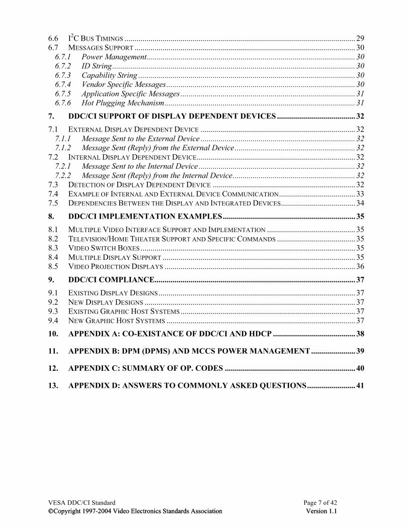
6.6 I2C BUS TIMINGS ................................................................................................................... 29 6.7 MESSAGES SUPPORT .............................................................................................................. 30
6.7.1 Power Management ........................................................................................................ 30 6.7.2 ID String ......................................................................................................................... 30 6.7.3 Capability String ............................................................................................................ 30 6.7.4 Vendor Specific Messages .............................................................................................. 30 6.7.5 Application Specific Messages ....................................................................................... 31 6.7.6 Hot Plugging Mechanism ............................................................................................... 31
7. DDC/CI SUPPORT OF DISPLAY DEPENDENT DEVICES ....................................... 32 7.1 EXTERNAL DISPLAY DEPENDENT DEVICE ............................................................................. 32
7.1.1 Message Sent to the External Device ............................................................................. 32 7.1.2 Message Sent (Reply) from the External Device ............................................................ 32
7.2 INTERNAL DISPLAY DEPENDENT DEVICE ............................................................................... 32 7.2.1 Message Sent to the Internal Device .............................................................................. 32 7.2.2 Message Sent (Reply) from the Internal Device ............................................................. 32
7.3 DETECTION OF DISPLAY DEPENDENT DEVICE ....................................................................... 32 7.4 EXAMPLE OF INTERNAL AND EXTERNAL DEVICE COMMUNICATION ...................................... 33 7.5 DEPENDENCIES BETWEEN THE DISPLAY AND INTEGRATED DEVICES ..................................... 34
8. DDC/CI IMPLEMENTATION EXAMPLES .................................................................. 35 8.1 MULTIPLE VIDEO INTERFACE SUPPORT AND IMPLEMENTATION ............................................ 35 8.2 TELEVISION/HOME THEATER SUPPORT AND SPECIFIC COMMANDS ....................................... 35 8.3 VIDEO SWITCH BOXES ........................................................................................................... 35 8.4 MULTIPLE DISPLAY SUPPORT ................................................................................................ 35 8.5 VIDEO PROJECTION DISPLAYS ............................................................................................... 36
9. DDC/CI COMPLIANCE.................................................................................................... 37 9.1 EXISTING DISPLAY DESIGNS .................................................................................................. 37 9.2 NEW DISPLAY DESIGNS ......................................................................................................... 37 9.3 EXISTING GRAPHIC HOST SYSTEMS ....................................................................................... 37 9.4 NEW GRAPHIC HOST SYSTEMS .............................................................................................. 37 10. APPENDIX A: CO-EXISTANCE OF DDC/CI AND HDCP ......................................... 38
11. APPENDIX B: DPM (DPMS) AND MCCS POWER MANAGEMENT ...................... 39
12. APPENDIX C: SUMMARY OF OP. CODES ................................................................. 40
13. APPENDIX D: ANSWERS TO COMMONLY ASKED QUESTIONS ........................ 41
VESA DDC/CI Standard Page 8 of 42 ©Copyright 1997-2004 Video Electronics Standards Association Version 1.1 ©Copyright 1997-2004 Video Electronics Standards Association Version 1.1
Table 1 : DDC Modes ......................................................................................................................9 Table 2 - Reference Documents .....................................................................................................11 Table 3 - I2C Notation ....................................................................................................................12 Table 4 : Examples of External Display Dependent Devices ........................................................15 Table 5 : Examples of Fixed I2C Address devices .........................................................................16 Table 6 : I2C Bus Notation .............................................................................................................17 Table 7 : Capability String Fields ..................................................................................................30 Table 8 - FAQ ................................................................................................................................41 Figure 1: Key Elements of a DDC/CI System ...............................................................................13 Figure 2 - Recommended SCL and SDA Line Terminations ........................................................37
VESA DDC/CI Standard Page 9 of 42 ©Copyright 1997-2004 Video Electronics Standards Association Version 1.1 ©Copyright 1997-2004 Video Electronics Standards Association Version 1.1
1. OVERVIEW
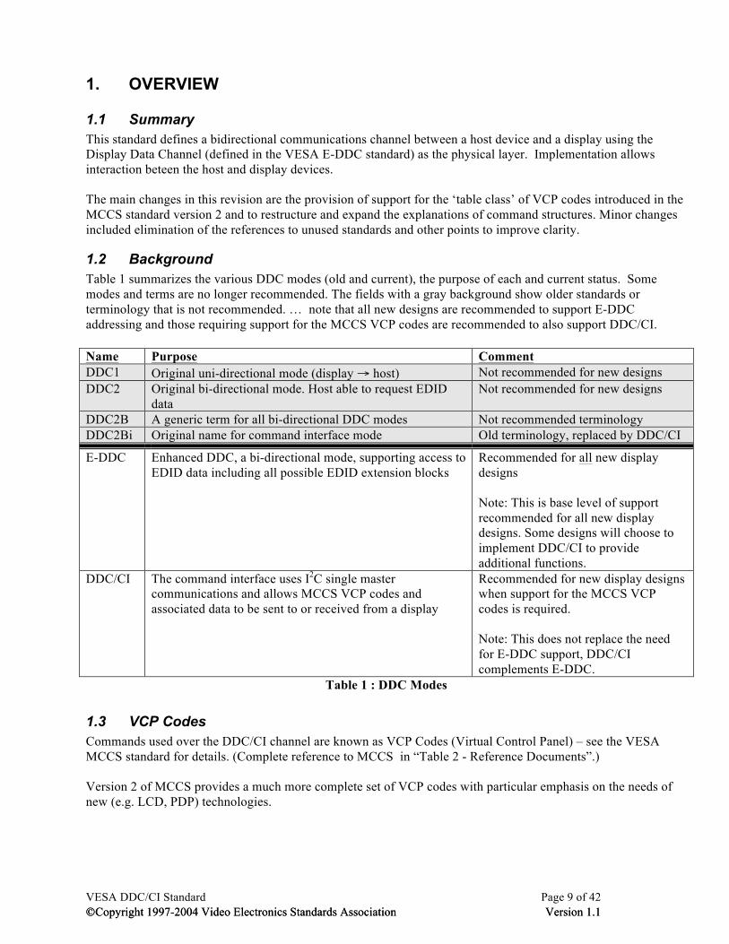
1.1 Summary This standard defines a bidirectional communications channel between a host device and a display using the Display Data Channel (defined in the VESA E-DDC standard) as the physical layer. Implementation allows interaction beteen the host and display devices. The main changes in this revision are the provision of support for the ‘table class’ of VCP codes introduced in the MCCS standard version 2 and to restructure and expand the explanations of command structures. Minor changes included elimination of the references to unused standards and other points to improve clarity.
1.2 Background Table 1 summarizes the various DDC modes (old and current), the purpose of each and current status. Some modes and terms are no longer recommended. The fields with a gray background show older standards or terminology that is not recommended. … note that all new designs are recommended to support E-DDC addressing and those requiring support for the MCCS VCP codes are recommended to also support DDC/CI. Name Purpose Comment DDC1 Original uni-directional mode (display → host) Not recommended for new designs DDC2 Original bi-directional mode. Host able to request EDID
data Not recommended for new designs
DDC2B A generic term for all bi-directional DDC modes Not recommended terminology DDC2Bi Original name for command interface mode Old terminology, replaced by DDC/CI
E-DDC Enhanced DDC, a bi-directional mode, supporting access to EDID data including all possible EDID extension blocks
Recommended for all new display designs Note: This is base level of support recommended for all new display designs. Some designs will choose to implement DDC/CI to provide additional functions.
DDC/CI The command interface uses I2C single master communications and allows MCCS VCP codes and associated data to be sent to or received from a display
Recommended for new display designs when support for the MCCS VCP codes is required. Note: This does not replace the need for E-DDC support, DDC/CI complements E-DDC.
Table 1 : DDC Modes
1.3 VCP Codes Commands used over the DDC/CI channel are known as VCP Codes (Virtual Control Panel) – see the VESA MCCS standard for details. (Complete reference to MCCS in “Table 2 - Reference Documents”.) Version 2 of MCCS provides a much more complete set of VCP codes with particular emphasis on the needs of new (e.g. LCD, PDP) technologies.
VESA DDC/CI Standard Page 10 of 42 ©Copyright 1997-2004 Video Electronics Standards Association Version 1.1
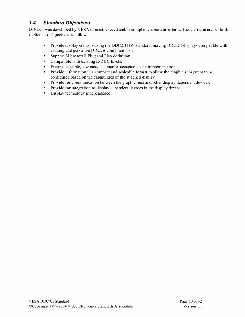
1.4 Standard Objectives DDC/CI was developed by VESA to meet, exceed and/or complement certain criteria. These criteria are set forth as Standard Objectives as follows :
• Provide display controls using the DDC2B HW standard, making DDC/CI displays compatible with existing and pervasive DDC2B compliant hosts.
• Support Microsoft® Plug and Play definition. • Compatible with existing E-DDC levels. • Ensure scaleable, low cost, fast market acceptance and implementation. • Provide information in a compact and scaleable format to allow the graphic subsystem to be
configured based on the capabilities of the attached display. • Provide for communication between the graphic host and other display dependent devices. • Provide for integration of display dependent devices in the display device. • Display technology independence.
VESA DDC/CI Standard Page 11 of 42 ©Copyright 1997-2004 Video Electronics Standards Association Version 1.1
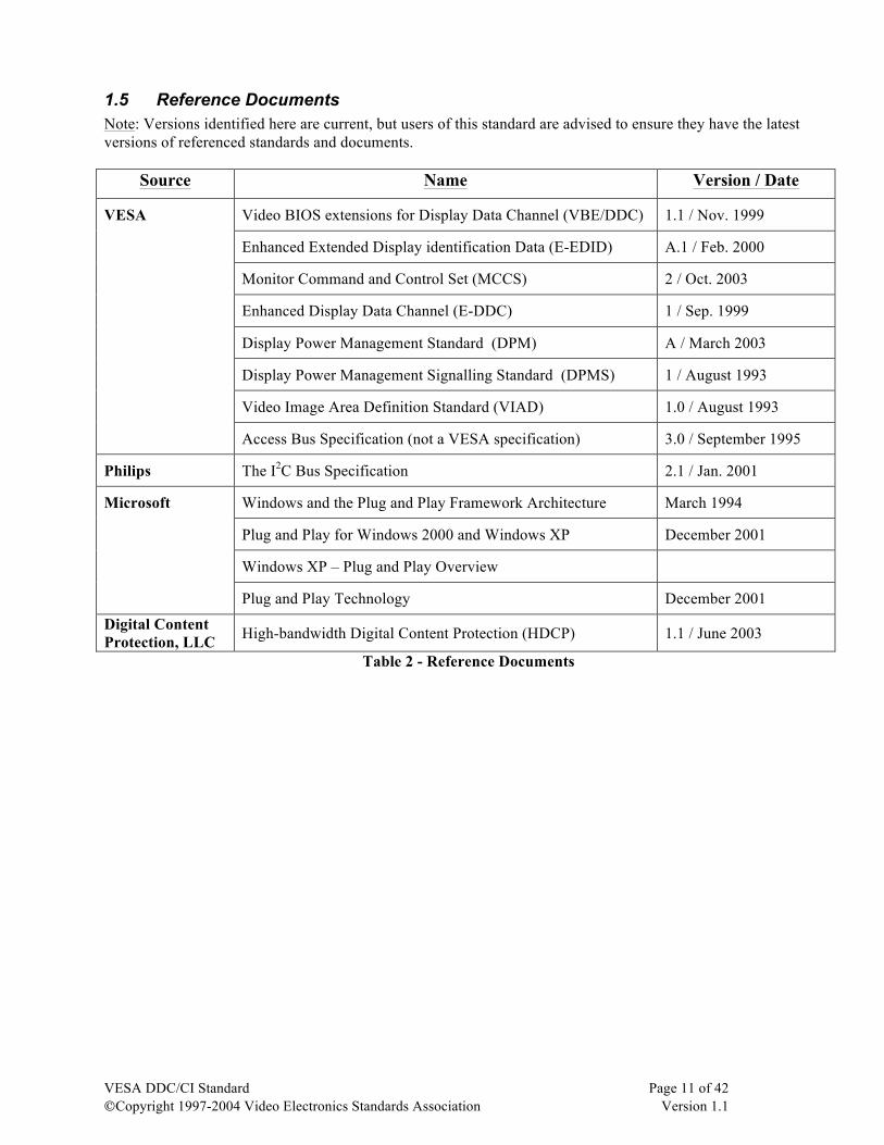
1.5 Reference Documents Note: Versions identified here are current, but users of this standard are advised to ensure they have the latest versions of referenced standards and documents.
Source Name Version / Date
VESA Video BIOS extensions for Display Data Channel (VBE/DDC) 1.1 / Nov. 1999
Enhanced Extended Display identification Data (E-EDID) A.1 / Feb. 2000
Monitor Command and Control Set (MCCS) 2 / Oct. 2003
Enhanced Display Data Channel (E-DDC) 1 / Sep. 1999
Display Power Management Standard (DPM) A / March 2003
Display Power Management Signalling Standard (DPMS) 1 / August 1993
Video Image Area Definition Standard (VIAD) 1.0 / August 1993
Access Bus Specification (not a VESA specification) 3.0 / September 1995
Philips The I2C Bus Specification 2.1 / Jan. 2001
Microsoft Windows and the Plug and Play Framework Architecture March 1994
Plug and Play for Windows 2000 and Windows XP December 2001
Windows XP – Plug and Play Overview
Plug and Play Technology December 2001
Digital Content Protection, LLC High-bandwidth Digital Content Protection (HDCP) 1.1 / June 2003
Table 2 - Reference Documents
VESA DDC/CI Standard Page 12 of 42 ©Copyright 1997-2004 Video Electronics Standards Association Version 1.1
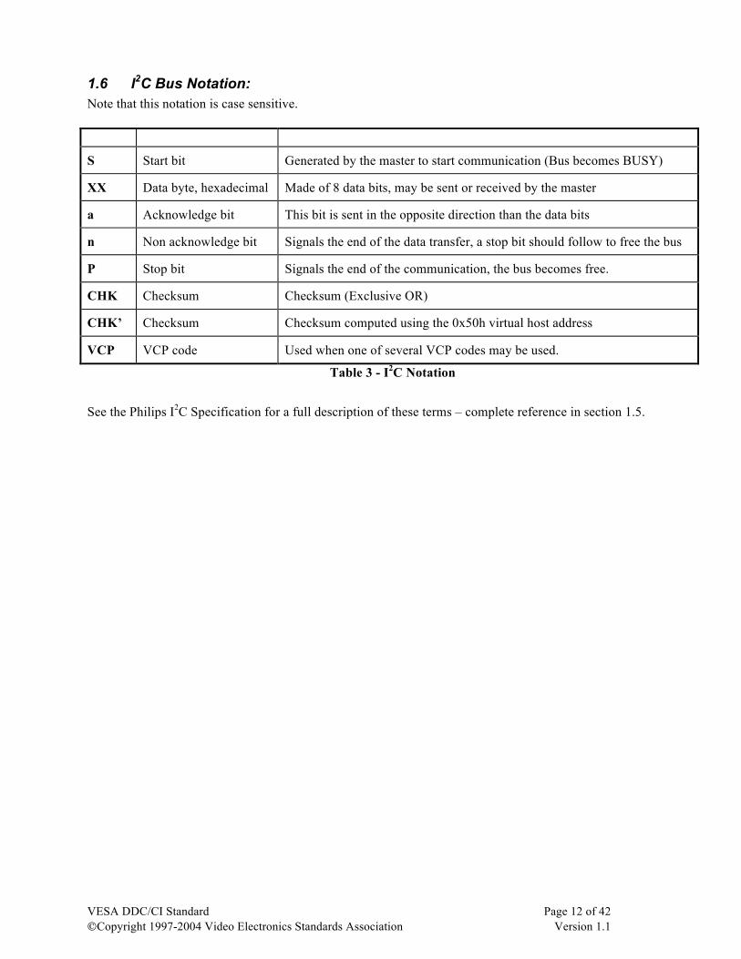
1.6 I2C Bus Notation: Note that this notation is case sensitive. Code Description Comment
S Start bit Generated by the master to start communication (Bus becomes BUSY)
XX Data byte, hexadecimal Made of 8 data bits, may be sent or received by the master
a Acknowledge bit This bit is sent in the opposite direction than the data bits
n Non acknowledge bit Signals the end of the data transfer, a stop bit should follow to free the bus
P Stop bit Signals the end of the communication, the bus becomes free.
CHK Checksum Checksum (Exclusive OR)
CHK’ Checksum Checksum computed using the 0x50h virtual host address
VCP VCP code Used when one of several VCP codes may be used.
Table 3 - I2C Notation
See the Philips I2C Specification for a full description of these terms – complete reference in section 1.5.
VESA DDC/CI Standard Page 13 of 42 ©Copyright 1997-2004 Video Electronics Standards Association Version 1.1
2. DDC/CI System Architecture
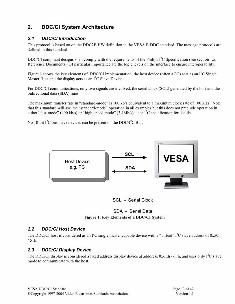
2.1 DDC/CI Introduction This protocol is based on on the DDC2B HW definition in the VESA E-DDC standard. The message protocols are defined in this standard. DDC/CI compliant designs shall comply with the requirements of the Philips I2C Specification (see section 1.5, Reference Documents). Of particular importance are the logic levels on the interface to ensure interoperability. Figure 1 shows the key elements of DDC/CI implementation, the host device (often a PC) acts as an I2C Single Master Host and the display acts as an I2C Slave Device. For DDC/CI communications, only two signals are involved, the serial clock (SCL) generated by the host and the bidirectional data (SDA) lines. The maximum transfer rate in “standard-mode” is 100 kb/s equivalent to a maximum clock rate of 100 kHz. Note that this standard will assume “standard-mode” operation in all examples but this does not preclude operation in either “fast-mode” (400 kb/s) or “high-speed mode” (3.4Mb/s) – see I2C specification for details. No 10-bit I2C bus slave devices can be present on the DDC/I2C Bus.
Host Devicee.g. PC
VESASCL
SDA
SCL - Serial Clock
SDA - Serial Data Figure 1: Key Elements of a DDC/CI System
2.2 DDC/CI Host Device The DDC/CI host is considered as an I2C single master capable device with a “virtual” I2C slave address of 0x50h / 51h.
2.3 DDC/CI Display Device The DDC/CI display is considered a fixed address display device at adddress 0x6Eh / 6Fh, and uses only I2C slave mode to communicate with the host.
VESA DDC/CI Standard Page 14 of 42 ©Copyright 1997-2004 Video Electronics Standards Association Version 1.1
2.4 Display Dependent Devices A display dependent device is physically located around or within the display and follows the same DDC/CI data protocol as the display device. Pointers, calibration and audio devices are examples of possible display dependent devices.
2.5 Fixed I2C Slave Address Devices This category of devices groups all the existing stand-alone and “dumb” I2C slave devices, such as memories, TV tuners, audio processors, etc. These devices can coexist and be connected to the DDC I2C bus. However, it is strongly recommended to limit their number, and locate them in the host. These devices are not expected to support hot-plugging nor to follow the DDC/CI data protocol, and as such, must be considered custom devices.
VESA DDC/CI Standard Page 15 of 42 ©Copyright 1997-2004 Video Electronics Standards Association Version 1.1
3. DDC/CI Hardware Implementation
3.1 Host Device HW requirements are similar to a DDC2B capable host.
3.2 Display Device The hardware requirements are similar to a DDC2B capable display.
3.3 Display Dependent devices Display dependent devices are classified into two types, external and internal, which can coexist without conflict. External devices are physically outside the display cabinet and may be detachable, internal devices are physically inside the display cabinet and will not usually be detachable.
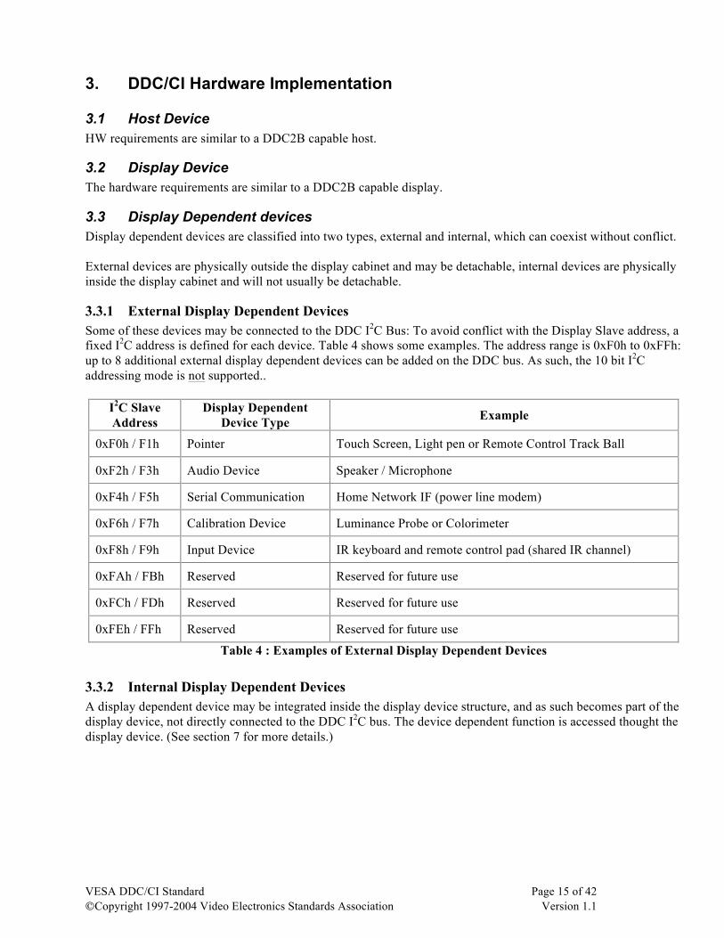
3.3.1 External Display Dependent Devices Some of these devices may be connected to the DDC I2C Bus: To avoid conflict with the Display Slave address, a fixed I2C address is defined for each device. Table 4 shows some examples. The address range is 0xF0h to 0xFFh: up to 8 additional external display dependent devices can be added on the DDC bus. As such, the 10 bit I2C addressing mode is not supported..
I2C Slave Address
Display Dependent Device Type Example
0xF0h / F1h Pointer Touch Screen, Light pen or Remote Control Track Ball
0xF2h / F3h Audio Device Speaker / Microphone
0xF4h / F5h Serial Communication Home Network IF (power line modem)
0xF6h / F7h Calibration Device Luminance Probe or Colorimeter
0xF8h / F9h Input Device IR keyboard and remote control pad (shared IR channel)
0xFAh / FBh Reserved Reserved for future use
0xFCh / FDh Reserved Reserved for future use
0xFEh / FFh Reserved Reserved for future use
Table 4 : Examples of External Display Dependent Devices
3.3.2 Internal Display Dependent Devices A display dependent device may be integrated inside the display device structure, and as such becomes part of the display device, not directly connected to the DDC I2C bus. The device dependent function is accessed thought the display device. (See section 7 for more details.)

VESA DDC/CI Standard Page 16 of 42 ©Copyright 1997-2004 Video Electronics Standards Association Version 1.1
3.4 Fixed address I2C devices Table 5 shows examples of devices that can be connected to the same I2C / DDC bus, each must have a 7 bit I2C slave address. The I2C addresses are defined and registered by Philips.
I2C Slave Address I2C Device
0x12h / 13h Smart Battery Charger
0x14h / 15h Smart Battery Selector
0x16h / 17h Smart Battery
0x80h / 81h Audio Processor
0x40h / 41h PAL / NTSC Decoder
0xA0h / A1h DDC2B Monitor (memory)
Table 5 : Examples of Fixed I2C Address devices
VESA DDC/CI Standard Page 17 of 42 ©Copyright 1997-2004 Video Electronics Standards Association Version 1.1
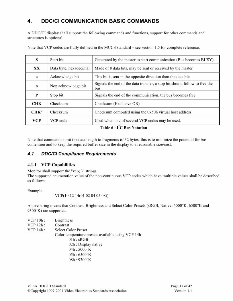
4. DDC/CI COMMUNICATION BASIC COMMANDS A DDC/CI display shall support the following commands and functions, support for other commands and structures is optional. Note that VCP codes are fiully defined in the MCCS standard – see section 1.5 for complete reference.
S Start bit Generated by the master to start communication (Bus becomes BUSY)
XX Data byte, hexadecimal Made of 8 data bits, may be sent or received by the master
a Acknowledge bit This bit is sent in the opposite direction than the data bits
n Non acknowledge bit Signals the end of the data transfer, a stop bit should follow to free the bus
P Stop bit Signals the end of the communication, the bus becomes free.
CHK Checksum Checksum (Exclusive OR)
CHK’ Checksum Checksum computed using the 0x50h virtual host address
VCP VCP code Used when one of several VCP codes may be used.
Table 6 : I2C Bus Notation
Note that commands limit the data length to fragments of 32 bytes, this is to minimize the potential for bus contention and to keep the required buffer size in the display to a reasonable size/cost.
4.1 DDC/CI Compliance Requirements
4.1.1 VCP Capabilities Monitor shall support the "vcp( )" strings. The supported enumeration value of the non-continuous VCP codes which have multiple values shall be described as follows: Example: VCP(10 12 14(01 02 04 05 08)) Above string means that Contrast, Brightness and Select Color Presets (sRGB, Native, 5000°K, 6500°K and 9300°K) are supported. VCP 10h : Brightness VCP 12h : Contrast VCP 14h : Select Color Preset Color temperature presets available using VCP 14h 01h : sRGB 02h : Display native 04h : 5000°K 05h : 6500°K 08h : 9300°K
VESA DDC/CI Standard Page 18 of 42 ©Copyright 1997-2004 Video Electronics Standards Association Version 1.1
4.1.2 MCCS Version The supported MCCS version can be determined by the following: A display compliant with this standard can support either MCCS version 1 or version 2 - version 1 is limited and primarily provides support for CRT displays.
mccs_ver()
Example: mccs_ver(2)
2h MCCS version 2 is supported
4.2 Optional Support
4.2.1 E-EDID Information E-EDID information may be retrieved as follows: Definition: e_edid_sel(block header Revision number (offset1(data1 data2)offset2( ))) Example:
e_edid_sel(40 01(02(00)0C(01 02 00)18(00)))
Above string allows the selected portions of a DI-EXT block (RGB sub-pixel and vertical pixel stripe orientation). 40h The EDID extension tag for a DI-EXT block 01h DI-EXT block revision number 02h Offset 1 of 02h into DI-EXT block – “digital interface” 00h Data associated with offset 1. 00h indicates that the display supports an analog interface 0Ch Offset 2 of 0Ch into DI-EXT block – “digital interface” 01h Data associated with offset 2. 01h indicates a RGB sub-pixel layout 02h Data associated with offset 2. 02h indicates a stripe configuration 00h Data associated with offset 2. 00h indicates that sub-pixel shape is undefined 18h Offset 3 of 18h into DI-EXT block is added to previous offsets 1 and 2 to give a combined
offset of 26h – “aspect ratio conversion modes” 00h Data associated with offset 3. 00h indicates that display does not support aspect ratio
conversion
VESA DDC/CI Standard Page 19 of 42 ©Copyright 1997-2004 Video Electronics Standards Association Version 1.1
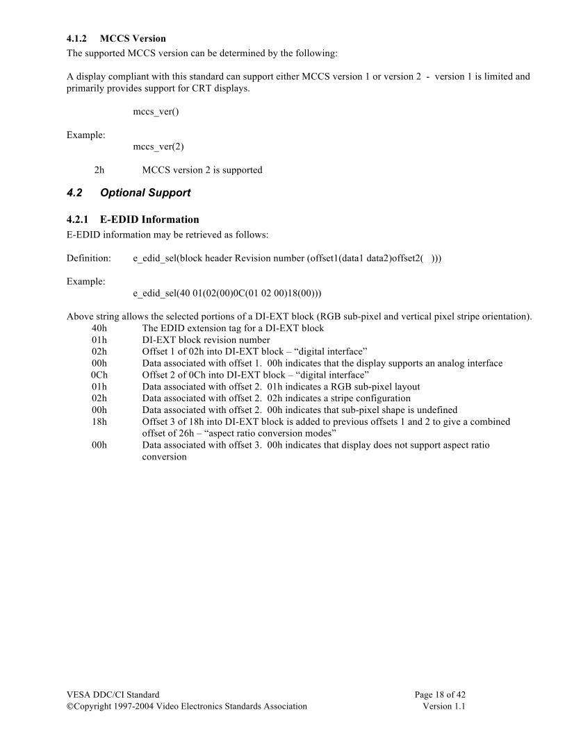
4.3 Get VCP Feature & VCP Feature Reply Sequence: -Send a request from host to the display for the adjustment data corresponding to a specified VCP code. - Wait - Receive the current setting data from the display to the host for the adjustment specified by the VCP code.
S-6Ea-51a-82a-01a-CPa-CHKa-P 6E Destination address 51 Source address 82 Length
01 Get VCP Feature COMMAND CP VCP opcode
S-6Fa-6Ea-88a-02a-RCa-CPa-TPa-MHa-MLa-SHa-SLa-CHK’n-P 6F Destination address 6E Source address 88 Length
02 VCP Feature reply op code RC Result Code 00h NoError 01h Unsupported VCP Code CP VCP opcode from Feature request message TP VCP type code 00h Set parameter 01h Momentary MH Maximum value High byte ML Maximum value Low byte SH Present value High byte SL Present value Low byte
Host Display
Display decodes and issues the reply message
Interval: The host should wait at least 40ms in order to enable the decoding and preparation of the reply message by the display
VESA DDC/CI Standard Page 20 of 42 ©Copyright 1997-2004 Video Electronics Standards Association Version 1.1
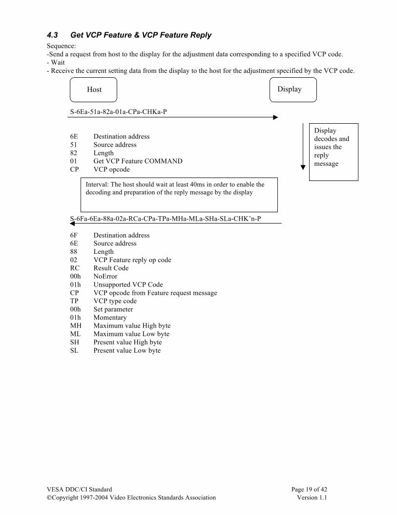
4.4 Set VCP Feature Send the adjustment data from host to the display corresponding to a specified VCP. S-6Ea-51a-84a-03a-CPa-SHa-SLa-CHKa 6E Destination address 51 Source address 84 Length
03 Set VCP Feature COMMAND CP VCP opcode SH High byte SL Low byte
4.5 Save Current Settings Save the current adjustment data to EEPROM (or other non-volatile storage) inside the display. S-6Ea-51a-81a-0Ca-CHKa-P 6E Destination address 51 Source address 81 Length
0C Save current settings command
Interval : The host should wait at least 200ms before sending the next message to the display.
Interval : The host should wait at least 50ms to ensure next message is received by the display.
Display decodes and changes the setting
Host Display
Host Display
Display decodes and saves the settings
VESA DDC/CI Standard Page 21 of 42 ©Copyright 1997-2004 Video Electronics Standards Association Version 1.1
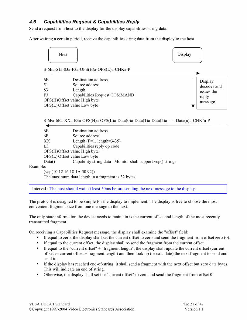
4.6 Capabilities Request & Capabilities Reply Send a request from host to the display for the display capabilities string data. After waiting a certain period, receive the capabilities string data from the display to the host. S-6Ea-51a-83a-F3a-OFS(H)a-OFS(L)a-CHKa-P 6E Destination address 51 Source address 83 Length
F3 Capabilities Request COMMAND OFS(H) Offset value High byte OFS(L) Offset value Low byte
S-6Fa-6Ea-XXa-E3a-OFS(H)a-OFS(L)a-Data(0)a-Data(1)a-Data(2)a------Data(n)a-CHK’n-P 6E Destination address 6F Source address XX Length (P=1, length=3-35)
E3 Capabilities reply op code OFS(H) Offset value High byte OFS(L) Offset value Low byte Data() Capability string data Monitor shall support vcp() strings
Example: (vcp(10 12 16 18 1A 50 92)) The maximum data length in a fragment is 32 bytes.
The protocol is designed to be simple for the display to implement: The display is free to choose the most convenient fragment size from one message to the next. The only state information the device needs to maintain is the current offset and length of the most recently transmitted fragment. On receiving a Capabilities Request message, the display shall examine the "offset" field:
• If equal to zero, the display shall set the current offset to zero and send the fragment from offset zero (0). • If equal to the current offset, the display shall re-send the fragment from the current offset. • If equal to the "current offset" + "fragment length", the display shall update the current offset (current
offset := current offset + fragment length) and then look up (or calculate) the next fragment to send and send it.
• If the display has reached end-of-string, it shall send a fragment with the next offset but zero data bytes. This will indicate an end of string.
• Otherwise, the display shall set the "current offset" to zero and send the fragment from offset 0.
Interval : The host should wait at least 50ms before sending the next message to the display.
Host Display
Display decodes and issues the reply message
VESA DDC/CI Standard Page 22 of 42 ©Copyright 1997-2004 Video Electronics Standards Association Version 1.1
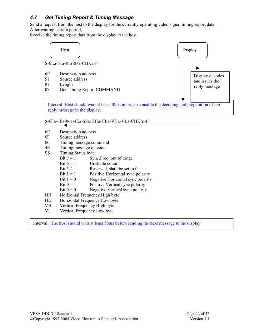
4.7 Get Timing Report & Timing Message Send a request from the host to the display for the currently operating video signal timing report data. After waiting certain period, Receive the timing report data from the display to the host. S-6Ea-51a-81a-07a-CHKa-P 6E Destination address 51 Source address 81 Length 07 Get Timing Report COMMAND S-6Fa-6Ea-06a-4Ea-SSa-HHa-HLa-VHa-VLa-CHK’n-P
6E Destination address 6F Source address 06 Timing message command 4E Timing message op code SS Timing Status byte
Bit 7 = 1 Sync.Freq. out of range Bit 6 = 1 Unstable count Bit 5-2 Reserved, shall be set to 0 Bit 1 = 1 Positive Horizontal sync polarity Bit 1 = 0 Negative Horizontal sync polarity Bit 0 = 1 Positive Vertical sync polarity Bit 0 = 0 Negative Vertical sync polarity
HH Horizontal Frequency High byte HL Horizontal Frequency Low byte VH Vertical Frequency High byte VL Vertical Frequency Low byte
Interval : The host should wait at least 50ms before sending the next message to the display.
Interval: Host should wait at least 40ms in order to enable the decoding and preparation of the reply message in the display.
Display decodes and issues the reply message
Host Display
VESA DDC/CI Standard Page 23 of 42 ©Copyright 1997-2004 Video Electronics Standards Association Version 1.1
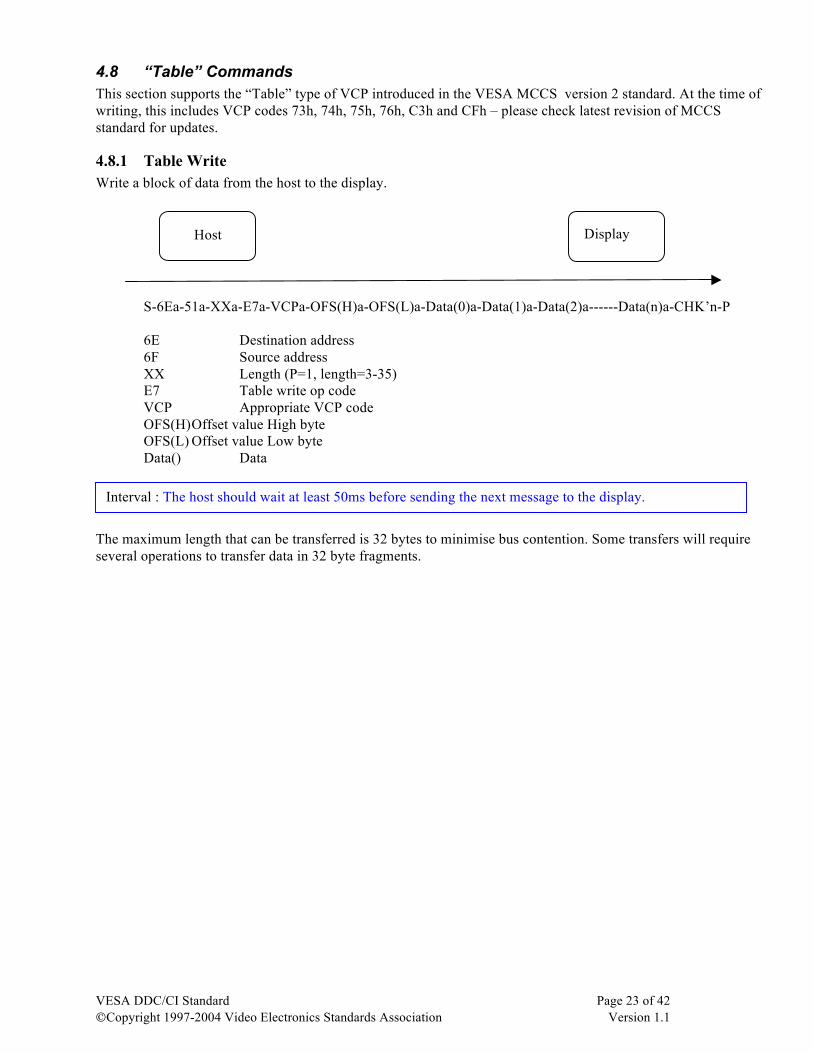
4.8 “Table” Commands This section supports the “Table” type of VCP introduced in the VESA MCCS version 2 standard. At the time of writing, this includes VCP codes 73h, 74h, 75h, 76h, C3h and CFh – please check latest revision of MCCS standard for updates.
4.8.1 Table Write Write a block of data from the host to the display. S-6Ea-51a-XXa-E7a-VCPa-OFS(H)a-OFS(L)a-Data(0)a-Data(1)a-Data(2)a------Data(n)a-CHK’n-P 6E Destination address 6F Source address XX Length (P=1, length=3-35)
E7 Table write op code VCP Appropriate VCP code OFS(H) Offset value High byte OFS(L) Offset value Low byte Data() Data
The maximum length that can be transferred is 32 bytes to minimise bus contention. Some transfers will require several operations to transfer data in 32 byte fragments.
Interval : The host should wait at least 50ms before sending the next message to the display.
Host Display
VESA DDC/CI Standard Page 24 of 42 ©Copyright 1997-2004 Video Electronics Standards Association Version 1.1
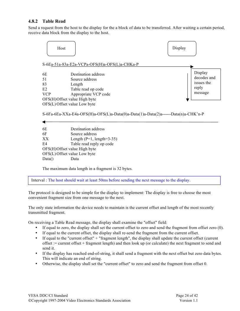
4.8.2 Table Read Send a request from the host to the display for the a block of data to be transferred. After waiting a certain period, receive data block from the display to the host. S-6Ea-51a-83a-E2a-VCPa-OFS(H)a-OFS(L)a-CHKa-P 6E Destination address 51 Source address 83 Length
E2 Table read op code VCP Appropriate VCP code OFS(H) Offset value High byte OFS(L) Offset value Low byte
S-6Fa-6Ea-XXa-E4a-OFS(H)a-OFS(L)a-Data(0)a-Data(1)a-Data(2)a------Data(n)a-CHK’n-P 6E Destination address 6F Source address XX Length (P=1, length=3-35)
E4 Table read reply op code OFS(H) Offset value High byte OFS(L) Offset value Low byte Data() Data
The maximum data length in a fragment is 32 bytes.
The protocol is designed to be simple for the display to implement: The display is free to choose the most convenient fragment size from one message to the next. The only state information the device needs to maintain is the current offset and length of the most recently transmitted fragment. On receiving a Table Read message, the display shall examine the "offset" field:
• If equal to zero, the display shall set the current offset to zero and send the fragment from offset zero (0). • If equal to the current offset, the display shall re-send the fragment from the current offset. • If equal to the "current offset" + "fragment length", the display shall update the current offset (current
offset := current offset + fragment length) and then look up (or calculate) the next fragment to send and send it.
• If the display has reached end-of-string, it shall send a fragment with the next offset but zero data bytes. This will indicate an end of string.
• Otherwise, the display shall set the "current offset" to zero and send the fragment from offset 0.
Interval : The host should wait at least 50ms before sending the next message to the display.
Host Display
Display decodes and issues the reply message
VESA DDC/CI Standard Page 25 of 42 ©Copyright 1997-2004 Video Electronics Standards Association Version 1.1
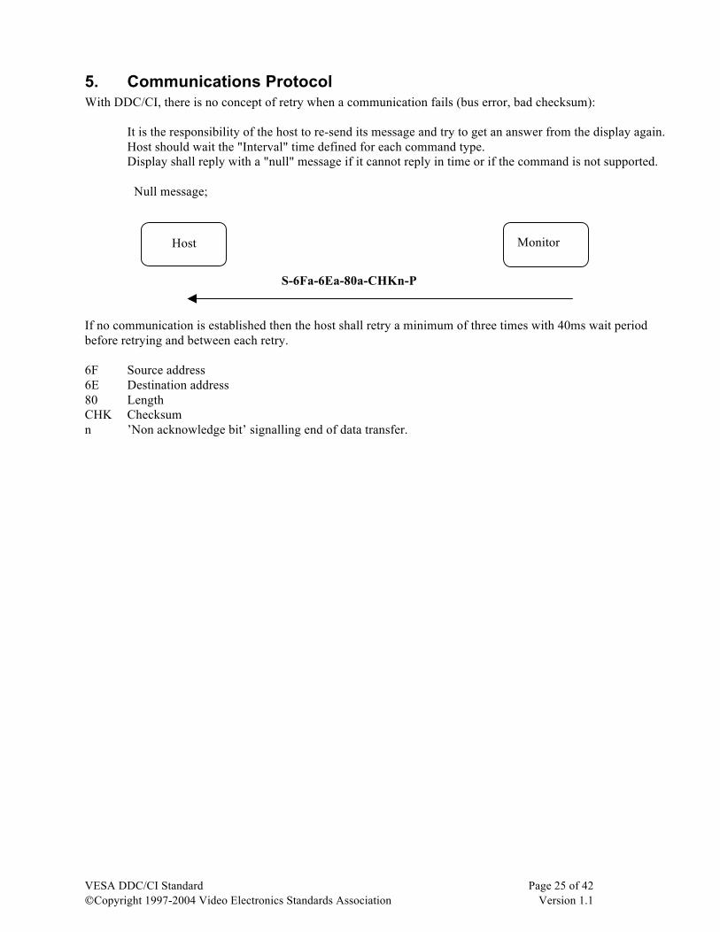
5. Communications Protocol With DDC/CI, there is no concept of retry when a communication fails (bus error, bad checksum):
It is the responsibility of the host to re-send its message and try to get an answer from the display again. Host should wait the "Interval" time defined for each command type. Display shall reply with a "null" message if it cannot reply in time or if the command is not supported.
Null message;
S-6Fa-6Ea-80a-CHKn-P If no communication is established then the host shall retry a minimum of three times with 40ms wait period before retrying and between each retry. 6F Source address 6E Destination address 80 Length CHK Checksum n ’Non acknowledge bit’ signalling end of data transfer.
Host Monitor
VESA DDC/CI Standard Page 26 of 42 ©Copyright 1997-2004 Video Electronics Standards Association Version 1.1
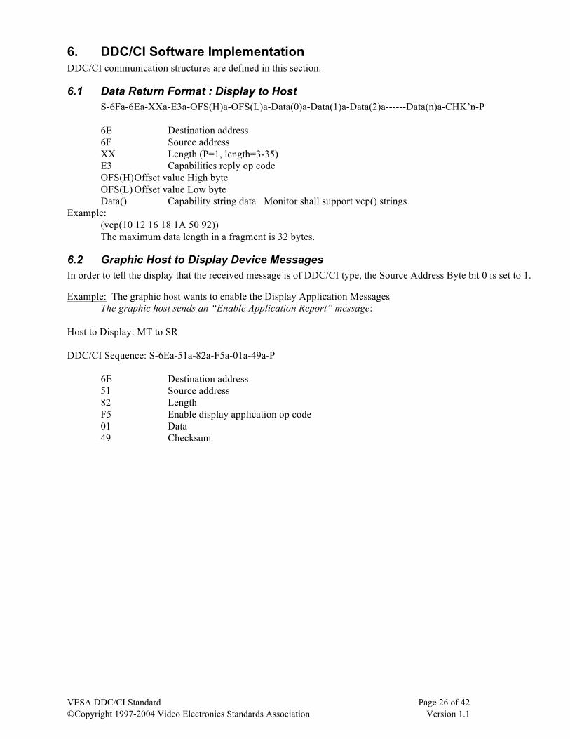
6. DDC/CI Software Implementation DDC/CI communication structures are defined in this section.
6.1 Data Return Format : Display to Host S-6Fa-6Ea-XXa-E3a-OFS(H)a-OFS(L)a-Data(0)a-Data(1)a-Data(2)a------Data(n)a-CHK’n-P 6E Destination address 6F Source address XX Length (P=1, length=3-35)
E3 Capabilities reply op code OFS(H) Offset value High byte OFS(L) Offset value Low byte Data() Capability string data Monitor shall support vcp() strings
Example: (vcp(10 12 16 18 1A 50 92)) The maximum data length in a fragment is 32 bytes.
6.2 Graphic Host to Display Device Messages In order to tell the display that the received message is of DDC/CI type, the Source Address Byte bit 0 is set to 1. Example: The graphic host wants to enable the Display Application Messages The graphic host sends an “Enable Application Report” message: Host to Display: MT to SR DDC/CI Sequence: S-6Ea-51a-82a-F5a-01a-49a-P
6E Destination address 51 Source address 82 Length
F5 Enable display application op code 01 Data 49 Checksum
VESA DDC/CI Standard Page 27 of 42 ©Copyright 1997-2004 Video Electronics Standards Association Version 1.1
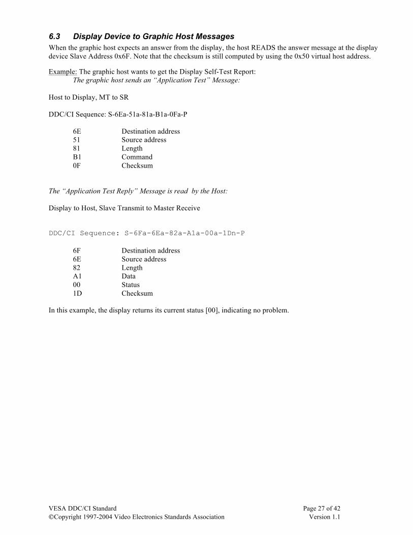
6.3 Display Device to Graphic Host Messages When the graphic host expects an answer from the display, the host READS the answer message at the display device Slave Address 0x6F. Note that the checksum is still computed by using the 0x50 virtual host address. Example: The graphic host wants to get the Display Self-Test Report: The graphic host sends an “Application Test” Message: Host to Display, MT to SR DDC/CI Sequence: S-6Ea-51a-81a-B1a-0Fa-P
6E Destination address 51 Source address 81 Length
B1 Command 0F Checksum
The “Application Test Reply” Message is read by the Host: Display to Host, Slave Transmit to Master Receive DDC/CI Sequence: S-6Fa-6Ea-82a-A1a-00a-1Dn-P
6F Destination address 6E Source address 82 Length
A1 Data 00 Status 1D Checksum
In this example, the display returns its current status [00], indicating no problem.
VESA DDC/CI Standard Page 28 of 42 ©Copyright 1997-2004 Video Electronics Standards Association Version 1.1
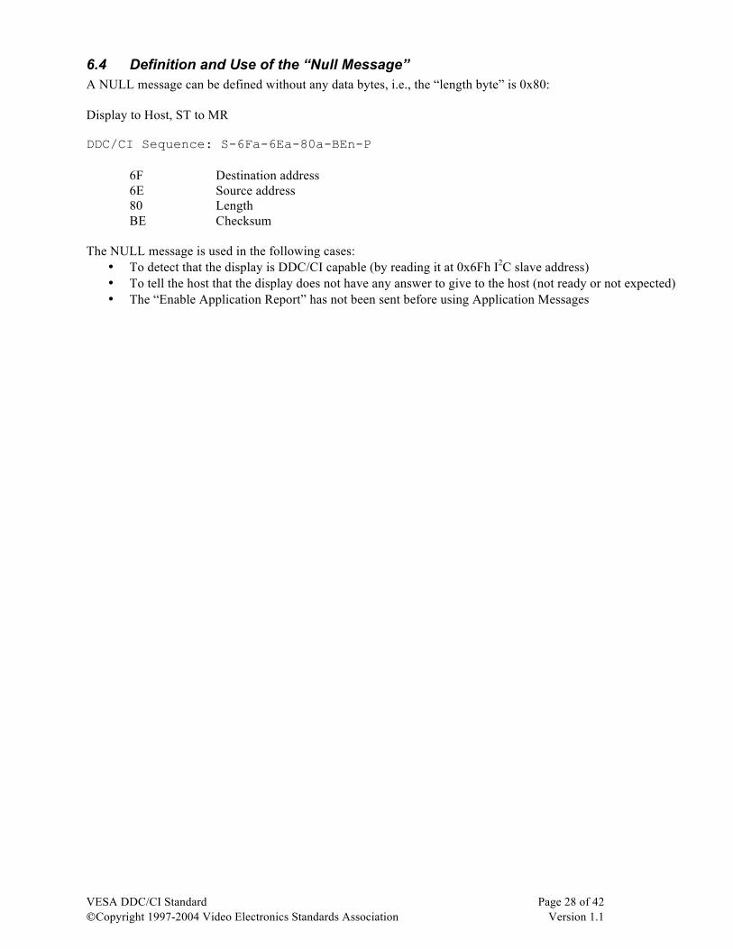
6.4 Definition and Use of the “Null Message” A NULL message can be defined without any data bytes, i.e., the “length byte” is 0x80: Display to Host, ST to MR DDC/CI Sequence: S-6Fa-6Ea-80a-BEn-P
6F Destination address 6E Source address 80 Length
BE Checksum The NULL message is used in the following cases:
• To detect that the display is DDC/CI capable (by reading it at 0x6Fh I2C slave address) • To tell the host that the display does not have any answer to give to the host (not ready or not expected) • The “Enable Application Report” has not been sent before using Application Messages
VESA DDC/CI Standard Page 29 of 42 ©Copyright 1997-2004 Video Electronics Standards Association Version 1.1
6.5 Communication Between the Host and its Devices Several basic rules apply to the DDC/CI host and its devices in order to have good communication performances.
6.5.1 Message Buffer Size Requirements The I2C bus specification requires that a host be able to send and receive messages of any size up to the maximum of131 bytes (127 + 4). But for DDC/CI, the maximum permitted length is 32 bytes of data to minimize the risk of bus contention and to keep the required buffer size in the display to a reasonable size/cost. Messages longer than 32 bytes must be transmitted as a number of 32 byte fragments, the last fragment may be less than 32 bytes if message is not a multiple of 32 bytes. It is recommended to have independent transmit and receive buffers in order to simplify the implementation of error recovery and retry mechanisms in case of failed communication. Obviously, a device must properly send and receive all its supported command and data structures. This determines the minimum internal data communication buffer size for proper display operation. The device shall acknowledge all received data bytes from the host, even if the message is larger than the maximum size supported by the device. If the host attempts to read more data bytes than specified by the “length byte”, extra bytes of any dummy value will be read, in order to avoid a “hang” situation. However, the Host is responsible to read the correct number of bytes. With DDC/CI, it is possible to share the same memory in the device for both the receive and transmit buffers, due to the smart host communication error recovery mechanism.
6.6 I2C Bus Timings The host must implement I2C bus error recovery systems (see section 5 and I2C Specification). The host shall abort and perform an error recovery if the SCL line is stretched low by other devices for more than 2 msec. Since devices are slave devices and not driving the SCL line, they do NOT need to implement a 2msec SCL Low Watchdog1 system, but must make sure that in a worst-case timing situation, the device does not stretch the clock low over 2 msec (i.e. MCU maximum interrupt latency). The SCL clock stretching duration should be kept as short as possible. Technical Clarification: When the host sends a message to the display, the host must wait at least 40 msec before trying to read an answer from the display in order to avoid I2C bus bandwidth overhead. Since the display commands are initiated by the end-user, the 40msec response latency (equivalent of several video frames or one keyboard scan debounce period) is not critical. If other I2C devices are on the bus, the time-interleaved message method is easier to implement on the host side.
1 “Watchdog” refers to a periodic check performed to detect if the SCL line has been driven low – may be implemented in firmware.
VESA DDC/CI Standard Page 30 of 42 ©Copyright 1997-2004 Video Electronics Standards Association Version 1.1
6.7 Messages Support Some simplifications can be done based on DDC/CI functionality and are described here.
6.7.1 Power Management If display power management can be controlled over DDC/CI, it shall be handled by using the MCCS VCP code. If the MCCS solution must coexist with DPM (DPMS), some guidelines are shown in section 11 of this document. However, if the host supports both MCCS and DPM, both methods must be used by the OS to notify the display of any change in the requested power management level.
6.7.2 ID String The ID String must be unique per device, and Vendor/Model Names must be consistent with EDID information.
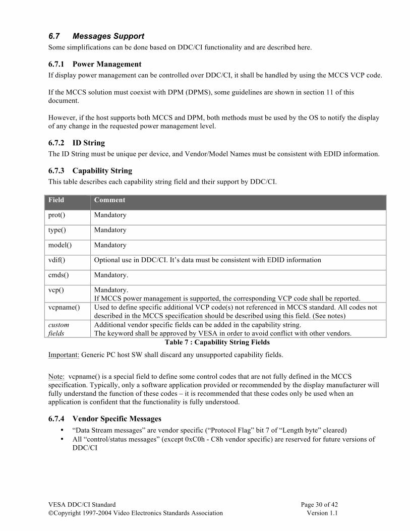
6.7.3 Capability String This table describes each capability string field and their support by DDC/CI. Field Comment
prot() Mandatory
type() Mandatory
model() Mandatory
vdif() Optional use in DDC/CI. It’s data must be consistent with EDID information
cmds() Mandatory.
vcp() Mandatory. If MCCS power management is supported, the corresponding VCP code shall be reported.
vcpname() Used to define specific additional VCP code(s) not referenced in MCCS standard. All codes not described in the MCCS specification should be described using this field. (See notes)
custom fields
Additional vendor specific fields can be added in the capability string. The keyword shall be approved by VESA in order to avoid conflict with other vendors.
Table 7 : Capability String Fields
Important: Generic PC host SW shall discard any unsupported capability fields.
Note: vcpname() is a special field to define some control codes that are not fully defined in the MCCS specification. Typically, only a software application provided or recommended by the display manufacturer will fully understand the function of these codes – it is recommended that these codes only be used when an application is confident that the functionality is fully understood.
6.7.4 Vendor Specific Messages • “Data Stream messages” are vendor specific (“Protocol Flag” bit 7 of “Length byte” cleared) • All “control/status messages” (except 0xC0h - C8h vendor specific) are reserved for future versions of
DDC/CI
VESA DDC/CI Standard Page 31 of 42 ©Copyright 1997-2004 Video Electronics Standards Association Version 1.1
6.7.5 Application Specific Messages The display does not have to initiate any message by itself:
• “Timing Report” message is sent only after the host sends “Get Timing Report” message. • “Key Report” message is sent only after the host sends “Get Key Report” message.
6.7.6 Hot Plugging Mechanism DDC/CI supports hot plugging, provided the display can detect a disconnection of the video cable. When the display detects an “unplug” event, it resets its DDC/CI function and disables the Application Message Reports. The host should regularly poll the device ID String to check for device presence (e.g. every 3 sec). If the DDC/CI slave address is not acknowledged after “trial and error recovery” attempts, the host shall consider that the DDC/CI function is no longer available (detached). If the DDC/CI slave address is acknowledged but a NULL message is returned in place of a application reply message, the host shall assume that a new DDC/CI device has been attached. Anytime a DDC/CI device is attached, the host should get both the ID String and Capability String, then enable the Application Message Report. Note: Some interface specifications, e.g. DVI, include hardware-based hot plugging detection mechanisms. In these cases, use of the DDC/CI based method is not recommended.
VESA DDC/CI Standard Page 32 of 42 ©Copyright 1997-2004 Video Electronics Standards Association Version 1.1
7. DDC/CI Support of Display Dependent Devices The DDC/CI communication allows optional addition of display dependent devices. As an example, a touch- screen device is used in this section. There are 2 different ways to implement the touch screen:
• As a slave device using DDC/CI protocol, but located at a different I2C slave address (e.g. 0xF0h /F1h) • As integrated/embedded in display device HW architecture (unique I2C address for both: 0x6Eh / 6Fh)
7.1 External Display Dependent Device In this example, the implementation is simple: a fixed I2C slave address is defined for the touch screen device (0xF0h / F1h). The application specific touch screen commands are defined in the Access Bus Locator Device Protocol spec.
7.1.1 Message Sent to the External Device The “source byte” (0x51h) is replaced by the odd device address (i.e. 0xF1h)
7.1.2 Message Sent (Reply) from the External Device The “source byte” (0x6Eh) is logically replaced by the even device address (i.e. 0xF0h)
7.2 Internal Display Dependent Device When the touch screen is integrated in the display device, there is only one I2C Slave address (0x6Eh / 6Fh) shared by both the display and the touch screen. In this configuration, the message discrimination / routing is done as follows:
7.2.1 Message Sent to the Internal Device The “source byte” (0x51h) is replaced by the external device odd address (i.e. 0xF1h).
7.2.2 Message Sent (Reply) from the Internal Device The “source byte” (0x6Eh) address byte is 0xF0h. Except for the destination I2C address, the communication of a display dependent device is the SAME for both internal and external devices.
7.3 Detection of Display Dependent Device The device detection is done by attempting to access the external I2C address first (acknowledge). Then the host must detect the presence of an internal device by sending an “Identification Request” to the internal device and check if the “Identification Reply” is successful. If not, a NULL message will be returned, meaning no internal devices are present.
VESA DDC/CI Standard Page 33 of 42 ©Copyright 1997-2004 Video Electronics Standards Association Version 1.1
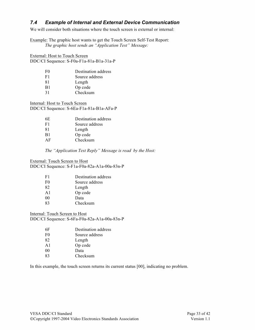
7.4 Example of Internal and External Device Communication We will consider both situations where the touch screen is external or internal: Example: The graphic host wants to get the Touch Screen Self-Test Report: The graphic host sends an “Application Test” Message: External: Host to Touch Screen DDC/CI Sequence: S-F0a-F1a-81a-B1a-31a-P
F0 Destination address F1 Source address 81 Length
B1 Op code 31 Checksum
Internal: Host to Touch Screen DDC/CI Sequence: S-6Ea-F1a-81a-B1a-AFa-P
6E Destination address F1 Source address 81 Length
B1 Op code AF Checksum
The “Application Test Reply” Message is read by the Host:
External: Touch Screen to Host DDC/CI Sequence: S-F1a-F0a-82a-A1a-00a-83n-P
F1 Destination address F0 Source address 82 Length
A1 Op code 00 Data 83 Checksum
Internal: Touch Screen to Host DDC/CI Sequence: S-6Fa-F0a-82a-A1a-00a-83n-P
6F Destination address F0 Source address 82 Length
A1 Op code 00 Data 83 Checksum
In this example, the touch screen returns its current status [00], indicating no problem.
VESA DDC/CI Standard Page 34 of 42 ©Copyright 1997-2004 Video Electronics Standards Association Version 1.1
7.5 Dependencies Between the Display and Integrated Devices Some commands sent to the display, such as those concerning power management, may affect integrated devices. Technical Clarification: When the host communicates with an internal device, the host MUST read any expected answer from the internal device before attempting to communicate with the display. This allows for cost optimized implementations, where both the display device and the internal device are sharing the same communication buffer.
VESA DDC/CI Standard Page 35 of 42 ©Copyright 1997-2004 Video Electronics Standards Association Version 1.1
8. DDC/CI Implementation Examples This chapter provides some examples of DDC/CI system implementations.
8.1 Multiple Video Interface Support and Implementation A unique DDC I2C bus for each video interface shall be implemented.
8.2 Television/Home Theater Support and Specific Commands Specific dedicated functions exist in the MCCS specification.
8.3 Video Switch Boxes Video switch boxes allow a single display to be attached to more than one computer system. System designers should assume that the video channel is linked with the DDC bus, meaning that switching the video channel from one host to another will also apply to the DDC channel.
8.4 Multiple Display Support Two forms of ‘expander boxes’ are common:
• Video amplifier o Used to replicate the same data on multiple screen e.g. conference room or school application
• Video splitter o Used to split the incoming signal into several areas to drive a large display consisting of several
discrete displays e.g. a video wall The expander box should primarily behave as a single display for the benefit of the host application software. In both examples, it is good design practice to put a DDC/CI “hub” that will have one DDC channel going to the PC and a separate independent I2C bus (I2C master) going to each attached display. This hub should build the correct EDID and properly translate and dispatch the DDC/CI display control commands to each attached display device. If the expander box supports both “amplifier” and “splitter” modes, the modes can be controlled by the host using a custom VCP code (using vcpname keyword in the capability string). For instance, in splitter mode, DDC/CI can be used to address each display individually by considering them as “internal only” display dependant devices. In the example of the 3 x 3 wall display (comprised of 9 discrete displays), this could be done by using free addresses (“source byte”) 00/01, 02/03, 04/05 for the top row, 06/07, 08/09, 0A/0B for the middle, and 0C/0D, 0E/0F, 10/11 for the bottom. For the duplicator mode, the previous enumeration could correspond to the video output channel number of the expander box. Note: Since the expander box is relaying messages to its attached displays, the response time must be increased from 40msec to 120msec.
VESA DDC/CI Standard Page 36 of 42 ©Copyright 1997-2004 Video Electronics Standards Association Version 1.1
8.5 Video Projection Displays Video projectors are display devices and can support DDC/CI. If a secondary monitor display can be connected to the video projector, a number of implementations are possible and can vary in complexity. One solution would be to consider the video projector as a multiple video expander box.
VESA DDC/CI Standard Page 37 of 42 ©Copyright 1997-2004 Video Electronics Standards Association Version 1.1
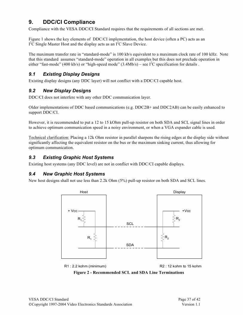
9. DDC/CI Compliance Compliance with the VESA DDC/CI Standard requires that the requirements of all sections are met. Figure 1 shows the key elements of DDC/CI implementation, the host device (often a PC) acts as an I2C Single Master Host and the display acts as an I2C Slave Device. The maximum transfer rate in “standard-mode” is 100 kb/s equivalent to a maximum clock rate of 100 kHz. Note that this standard assumes “standard-mode” operation in all examples but this does not preclude operation in either “fast-mode” (400 kb/s) or “high-speed mode” (3.4Mb/s) – see I2C specification for details .
9.1 Existing Display Designs Existing display designs (any DDC layer) will not conflict with a DDC/CI capable host.
9.2 New Display Designs DDC/CI does not interfere with any other DDC communication layer. Older implementations of DDC based communications (e.g. DDC2B+ and DDC2AB) can be easily enhanced to support DDC/CI. However, it is recommended to put a 12 to 15 kOhm pull-up resistor on both SDA and SCL signal lines in order to achieve optimum communication speed in a noisy environment, or when a VGA expander cable is used. Technical clarification: Placing a 12k Ohm resistor in parallel sharpens the rising edges at the display side without significantly affecting the equivalent resistor on the bus or the maximum sinking current, thus allowing for optimum communication.
9.3 Existing Graphic Host Systems Existing host systems (any DDC level) are not in conflict with DDC/CI capable displays.
9.4 New Graphic Host Systems New host designs shall not use less than 2.2k Ohm (5%) pull-up resistor on both SDA and SCL lines.
+Vcc +Vcc
DisplayHost
SCL
SDA
+ Vcc
R1
R2R1
R2
R2 : 12 kohm to 15 kohmR1 : 2.2 kohm (minimum) Figure 2 - Recommended SCL and SDA Line Terminations
VESA DDC/CI Standard Page 38 of 42 ©Copyright 1997-2004 Video Electronics Standards Association Version 1.1
10. Appendix A: Co-existance of DDC/CI and HDCP
Care must be taken if the DDC/CI link is being used for multiple puposes … for example, if it is being used both to control a display and for key exchange in HDCP (High-bandwidth Digital Content Protection) scheme. HDCP has a number of maximum response times for communication and, if these are exceeded, communication will be interrupted - see table 2-1 of HDCP System specification (version 1.1) for a summary.
Caution: All designers and users of DDC/CI should ensure that they are compliant with the appropriate standards and, in particular, that control of the bus is released whenever possible.
VESA DDC/CI Standard Page 39 of 42 ©Copyright 1997-2004 Video Electronics Standards Association Version 1.1
11. APPENDIX B: DPM (DPMS) and MCCS Power Management Note: Appendixes are NOT part of the standard. While DPM and MCCS power management can coexist on the display side, conflict can result if they are not handled properly by the host. For best results, if the host supports both power management systems, they should be used together, as follows: In a display supporting both DPM and MCCS, the recommended rules are: A. The GetVCP(power management) always returns the current physical monitor power state. B. By default, the DPM solution is used. C. The MCCS solution is used over DPM once:
• The host has sent “Enable Application Report” message, • AND has set the power management level using the SetVCP() command message.
D. When the video cable is DISCONNECTED: • (e.g. sensing VGA Pin 9), DPM is used. • If the “Disable Application Report” message is received by the display, DPM is used.
The implementation in the Graphic Host driver is possible (ACPI-On Now Power Management) using:
DWORD __cdecl GetMonitorPowerStateCaps(DEVNODE devnode)
Parameters: None. Returns: Bitmask of: CM_POWERSTATE_ON CM_POWERSTATE_OFF
When the display uses the DPM mode by default, using “GetVCP(0xD6)” will then report the Display Current power management level, regardless of the power management request’s source. As such, if the monitor enters into a safety mode (X-Ray protect, for example), Power Off mode will automatically follow. If the host then sends GetVCP(0xD6), the display will naturally respond 00. Zero power and host wake-up by a device: If the host is in stand-by mode, a device could wake-up the host (interrupt) by sending the Start/Stop bit sequence on the I2C bus.
VESA DDC/CI Standard Page 40 of 42 ©Copyright 1997-2004 Video Electronics Standards Association Version 1.1
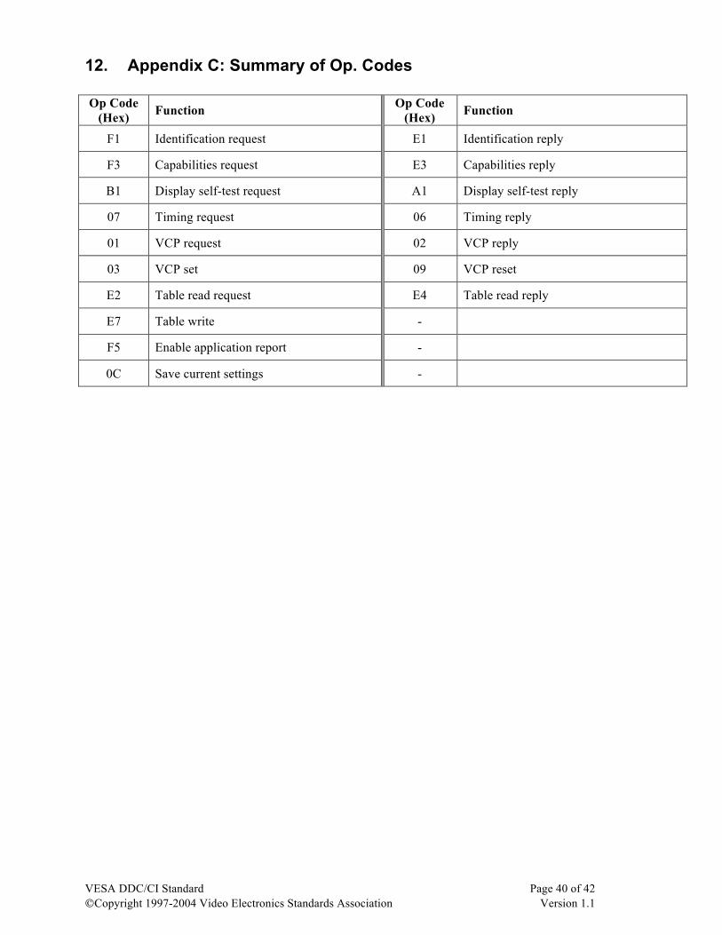
12. Appendix C: Summary of Op. Codes Op Code
(Hex) Function Op Code (Hex) Function
F1 Identification request E1 Identification reply
F3 Capabilities request E3 Capabilities reply
B1 Display self-test request A1 Display self-test reply
07 Timing request 06 Timing reply
01 VCP request 02 VCP reply
03 VCP set 09 VCP reset
E2 Table read request E4 Table read reply
E7 Table write -
F5 Enable application report -
0C Save current settings -
VESA DDC/CI Standard Page 41 of 42 ©Copyright 1997-2004 Video Electronics Standards Association Version 1.1
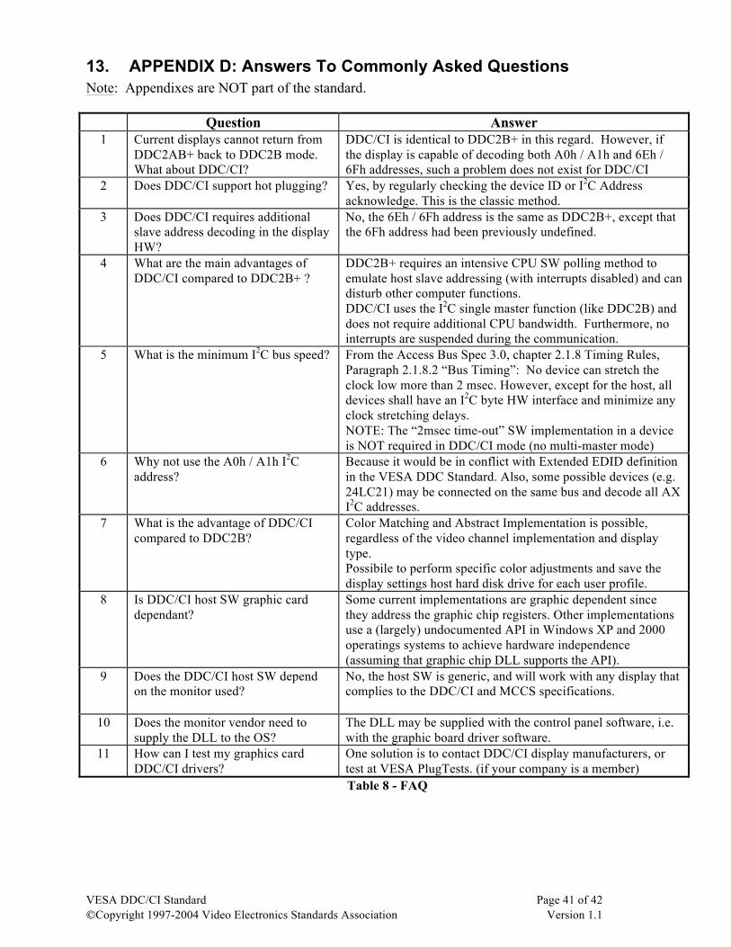
13. APPENDIX D: Answers To Commonly Asked Questions Note: Appendixes are NOT part of the standard.
Question Answer 1 Current displays cannot return from
DDC2AB+ back to DDC2B mode. What about DDC/CI?
DDC/CI is identical to DDC2B+ in this regard. However, if the display is capable of decoding both A0h / A1h and 6Eh / 6Fh addresses, such a problem does not exist for DDC/CI
2 Does DDC/CI support hot plugging? Yes, by regularly checking the device ID or I2C Address acknowledge. This is the classic method.
3 Does DDC/CI requires additional slave address decoding in the display HW?
No, the 6Eh / 6Fh address is the same as DDC2B+, except that the 6Fh address had been previously undefined.
4 What are the main advantages of DDC/CI compared to DDC2B+ ?
DDC2B+ requires an intensive CPU SW polling method to emulate host slave addressing (with interrupts disabled) and can disturb other computer functions. DDC/CI uses the I2C single master function (like DDC2B) and does not require additional CPU bandwidth. Furthermore, no interrupts are suspended during the communication.
5 What is the minimum I2C bus speed? From the Access Bus Spec 3.0, chapter 2.1.8 Timing Rules, Paragraph 2.1.8.2 “Bus Timing”: No device can stretch the clock low more than 2 msec. However, except for the host, all devices shall have an I2C byte HW interface and minimize any clock stretching delays. NOTE: The “2msec time-out” SW implementation in a device is NOT required in DDC/CI mode (no multi-master mode)
6 Why not use the A0h / A1h I2C address?
Because it would be in conflict with Extended EDID definition in the VESA DDC Standard. Also, some possible devices (e.g. 24LC21) may be connected on the same bus and decode all AX I2C addresses.
7 What is the advantage of DDC/CI compared to DDC2B?
Color Matching and Abstract Implementation is possible, regardless of the video channel implementation and display type. Possibile to perform specific color adjustments and save the display settings host hard disk drive for each user profile.
8 Is DDC/CI host SW graphic card dependant?
Some current implementations are graphic dependent since they address the graphic chip registers. Other implementations use a (largely) undocumented API in Windows XP and 2000 operatings systems to achieve hardware independence (assuming that graphic chip DLL supports the API).
9 Does the DDC/CI host SW depend on the monitor used?
No, the host SW is generic, and will work with any display that complies to the DDC/CI and MCCS specifications.
10 Does the monitor vendor need to supply the DLL to the OS?
The DLL may be supplied with the control panel software, i.e. with the graphic board driver software.
11 How can I test my graphics card DDC/CI drivers?
One solution is to contact DDC/CI display manufacturers, or test at VESA PlugTests. (if your company is a member) Table 8 - FAQ
VESA DDC/CI Standard Page 42 of 42 ©Copyright 1997-2004 Video Electronics Standards Association Version 1.1
THIS PAGE INTENTIONALLY LEFT BLANK
Related Documents